83
Implementation Of Water Level Conditioning
System Using Wireless Multi-Point
Communication
Ohnmar Htwe, Myo Maung Maung, Hla Myo Tun
Abstract: Wireless communication is the most popular in these days. Recently, people are trying to use the wireless communication systems in home
appliances. In this system that is designed and development of a water level conditioning system using wireless, which is being used to control the water distribution system. The development system based on the wireless RF (Radio Frequency) technology which can be installed in industries, departments, domestics and so on. The level controller is used with ultrasonic sensors to sense the level of water in the tanks and a reservoir. The system used microcontrollers,thesecontrollers have the ability to detect the level of water in a Tank1, Tank2 and a Reservoir, and then display the status of water on LCD screen, and moreover the buzzer will be work depending on the condition of water level in a reservoir. The main objectives of this paper are to design and develop a wireless water level conditioning system using point-to-multi-point RF communication technology. It is reliable because it has no problems arising after installation such as a breakage of wire.
Keywords: Radio Frequency (RF), ultrasonic sensor, microcontroller
————————————————————
I.
I
NTRODUCTIONSustainability of available water resource in many regions of the world is now a dominant issue. The problem is related to poor water allocation, inefficient use, lack of adequate and integrated water management. Water is commonly used for agriculture, industries and domestic consumption. This paper is discussed about water level conditioning system using water level sensors with wireless communication between controllers placed at the overhead tanks and the sump. So the system basically operated with three controllers and RF transceiver modules. This system is composed of ultrasonic sensor, two microcontrollers, LCD display and RF modules for wireless communication. NRF24L01 RF module is used for wireless communication system. Data transmission is used with SPI (Serial Peripheral Interface) for point-to-multipoint communication. SPI is a synchronous protocol; the data is clocked along with a clock signal (SCK). The clock signal controls when data is changed and when is should be read. Since SPI is synchronous, the clock rate can vary, unlike RS-232 style communication. SPI is a data exchange protocol. As data is being clock out, new data is being clock in. Data is always exchange between devices. No device can just be a transmitter or just a receiver in SPI. However, each device has two data lines, one for input and one for output. These data exchange are controlled by the clock line, SCK, which is controlled by the master device. More and more tanks can be
connected to this system because of multi-point
communication system. The following are the objectives of the research project to ensure it meets the aim:
To know the sensing equipment for measuring water
level.
To know the usage of motor as a valve controller.
To analyze RF technology applied in this application.
II.
D
ESIGN OFW
IRELESSD
ATAC
OMMUNICATIONS
YSTEMIn this system, it uses three Radio Frequency (RF) transceivers along with a microcontroller each installed at the overhead tank and a reservoir. Addition, it uses PIC18F4550 which receives signals from the transmitters and send these data to master microcontroller. In receiver unit section, PIC18F4550 microcontroller which interprets and effectively
communicates the status of the water overhead tanks via an integrated LCD display. The water level indicators shows the water level of tank1,tank2 and in reservoir as high or low level using ultrasonic sensors. RF transmitters send these signals to RF receiver at the reservoir using SPI interfacing protocol.Moreover, it interprets a buzzer that beeps briefly when there is no water in a reservoir or there is something circuit errors and loss of data transmission. Suppose an error or loss of data occurs during transmission, then the system is programmed to retransmit the data. The block diagram of Water Level Conditioning System using Multi-point RF Communication is shown in Figure 1.
Level Sensor (Ultrasonic) Microcontroller RF Receiver
Buzzer Microcontroll
-er
RF Transmitter Level Sensor
(Ultrasonic) Upper
Tank 1
Display
Microcontroll -er
RF Transmitter Level Sensor
(Ultrasonic) Upper
Tank 2
Resercoir
Figure1. Block Diagram of Water Level Conditioning System Using Multi-point RF Communication
III.
S
YSTEMD
ESIGN ANDI
MPLEMENTATIONThis system consists of two main parts: interfacing with PIC microcontrollers with RF module and wireless point-to-multipoint commination. The following are the main components and the operations of theirs are used in this application.
A.
Objectives
industries. The wireless communication system used in water distribution system is rarely used in these days. This system can provide many benefits to the users.
B. System Benefits
i. System is low cost and easy to install of wireless
communication.
ii. The system was success to transfer data at the
short-range using wireless communication network and flexible to apply.
iii. The water level indication sensor is the most popular
electric components in these days that can shows the level of water simply and easy to implement.
(1) RF (Radio Frequency) Module
An RF module (radio frequency module) is a usually small electronics device used to transmit and /or receive radio signals between two devices. The specifications of the nRF24L01 are;
i. Frequency range – 2.4 to 2.5 GHz
ii. Maximum data rate is 1000 kbps
iii. Minimum supply voltage – 1.9 V to 3.6 V
iv. Multi-channel operation - 125 channels
v. Distance travel – 10m to 150m
Figure 2.nRF24L01 Module
nRF24L01 is a single-chip radio transceiver for the worldwide 2.4-2.5GHz ISM band. The transceiver consists of a fully integrated frequency synthesizer, a power amplifier, a crystal oscillator and a modulator. Output power and frequency channels are easily programmable by use of the 3-wire serial interface. Current consumption is very low, only 10.5mA at an output power of -5dBm and 18mA in receive mode. Built-in power Down modes makes power saving easily reliable.
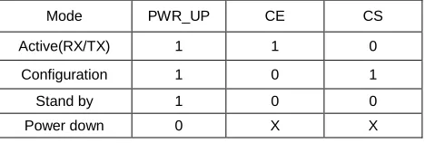
(1).1Mode of operation
The nRF24L01 can be set in the following main depending on three control pins:
Table I
nRF24L01 main modes
Mode PWR_UP CE CS
Active(RX/TX) 1 1 0
Configuration 1 0 1
Stand by 1 0 0
Power down 0 X X
The nRF24L01 has two active (RX/TX) modes:
i. ShockBurst
ii. Direct Mode
The device functionally in these modes is decided by the content of a configuration word. The nRF2401 can be programmed using a 3-wire interface where the data rate is decided by the speed of the microcontroller. By allowing the digital part of the application to run at low speed while maximizing the data rate on the RF link, the nRFShockBurst mode reduces the average current consumption in applications considerably. The shockBurst technology used on-chip FIFO to clock in data at a low data rate and transmit at a very high rate thus enabling extremely power reduction. When operating th nRF2401 in ShockBurst, we gain access to the high data rated (1 Mbps) offered by the 2.4 GHz band without the need of costly, high-speed microcontroller (MCU) for data processing. By putting all high signal processing related to RF protocol on-chip, the nRF201 offers the following benefits:
i. Highly reduced current consumption
ii. Lower system cost ( facilitates use of less expensive
microcontroller)
iii. Greatly reduced risk of ‗on-air‘ collisions due to short transmission time
(2) Microcontroller
PIC 18F4550 microcontroller is used as the main processor of this system.
RA3
RA4 Ultrasonic
Sensor
RE0
RE1 Valve
Controllers
RB5 Alarm Signal
RD7
RD6
RD5
RD4
LCD Display RB2
RB1
RB0
RC7
RF Receiver MCLR
VDD
VSS
VDD VSS +5V
+5V
PI
C
18
F4
55
0
RC0
RC1 RF
Receiver
Figure 3. PIC 18F4550 Microcontroller Pins Assign
This processor was chosen because of its good features and
integrated peripherals. Its portability and low-power
consumption design can satisfy the prolonged outdoor work. Three ultrasonic sensors are used in this system so that this controller is the most suitable to use to interface three sensors and wireless communication.
(3) Ultrasonic sensor
85
for water level indication. Basic steps of Programming for Ultrasonic Distance Measurement:
i. Provide TRIGGER to ultrasonic module
ii. Listen for Echo
iii. Start Timer when Echo High is received
iv. Stop Timer when Echo goes low
v. Convert it to Distance
vi. Display the Distance measurement
Figure 4. Ultrasonic HC-SR04 sensor
(4) SPI(Serial Peripheral Interface) Interfacing Protocol
SPI stands for Serial Peripheral Interface. SPI is synchronous
protocol that allows a master device to initialize
communication with a slave device. Data is exchange between these devices. SPI is implemented in the PICmicro MCU by a hardware module called the synchronous serial port or the Master synchronous serial port. This module is built into
many different PICmicro devices. It allows serial
communication between two or more devices at a high speed and is reasonably easy to implement. SPI is a serial interface using these signals;
i. SS: Ship Select or Slave Select; when this signal goeslow, the slave will listen for SPI clock and data signals.
ii. SCK: Serial Clock; this controls when data is sent and when it is read.
iii. SDO: Serial Data Output; this signal carries the data sent out of the device.
iv. SDI: Serial Data Input; this signals carries the data into the device.
IV.
S
OFTWAREI
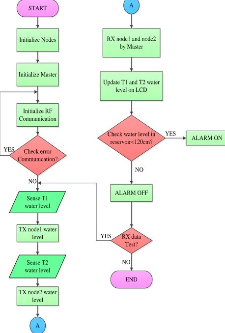
MPLEMENTATIONThe system flowchart of wireless water level conditioning system is shown in figure 5. After turning on the device, it automatically initializes the hardware, RF module and SPI interfacing protocol. Then it gets the water level data from water level sensors and then sending these signals to nRF24L01 receiver. Firstly, we have to initialize nodes, master and data communication before starting system. Secondly, check there is error in communication or not. If there are any errors in data transmission system, then the sensors are checking the water level of tank1 and tank2. After sensing these signals, has sent to the RF receiver which is the main MCU. Thirdly, check the water level of main reservoir. The ON/OFF conditions of buzzer are depending on the signals. Finally, if the transmitting is being texted, go back to second state, if not, the system will be stopped.
START
Initialize Nodes
Initialize Master
Initialize RF Communication
Check error Communication?
TX node1 water level
TX node2 water level
A
A
RX node1 and node2 by Master
Update T1 and T2 water level on LCD
Check water level in reservoir<120cm?
ALARM OFF
ALARM ON
RX data Test?
END YES
NO
YES
NO
YES
NO Sense T1
water level
Sense T2 water level
Figure 5.System flowchart of wireless water level conditioning system
The conditions of water level are shown on Liquid Crystal Display (LCD). To define the water level of Tank1 and Tank2, (1feet, 23cm, 20cm) water storage is chosen. For (1 feet, 1 feet, 22cm) water storage reservoir, 15cm is defined as a low level. For the real time condition, we can define any value to show the value of water level for any size of overhead Tanks and a reservoir.
V.
H
ARDWARET
ESTR
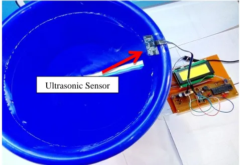
ESULTSThe connection of Tank1, Tank2 and reservoir are connected using SPI network protocol. NRF24L01 RF module is using for this application because of the device is the most suitable for point-to-multipoint communication system. Moreover, the important thing is to choose the brain of this system, PIC18F4550 is chosen due to simulating of three of ultrasonic sensors and multi-point communication system. For sensing the level of water, ultrasonic (HC-SR04) sensor is used. And also, 4×20 LCD display is used to show the conditions of water levels for overheads Tanks, reservoir and other conditions. Figure 6. shows the sensing of water level in reservoir using ultrasonic module.
Figure 6. The sensing of water level in reservoir using ultrasonic module
Figure 7.The water levels of Tank1, Tank2 and reservoir on LCD
Figure 8. Tank1 and Tank2 water levels are reached low level
Figure 9. shows the overview of Tank1 and Tank2
Figure 10.shows the water level of Tank2 is reached low level
According to the usage of water from Tank1 and Tank2, unfortunately the water level of tank1 also reached low level whereas the level of Tank2 is reached high level (4cm) which is shown figure 11. From these results, the water level of Tank1 and Tank2 is defined as high level (5cm) and low level (18cm) from water level sensor to the surface of water. And then the water level in reservoir is reached above 15cm, the buzzer is used as an alarm signal, if not, which is increased to high level below 15cm so that no need to work buzzer.
Figure 11. The water level of Tank2 is reached high level Ultrasonic Sensor
RF Receiver
Buzzer
Ultrasonic Water level
sensors
RF Trans-mitters
Tank1 Tank2
Water Levels
87
VII.
A
PPLICATION ANDA
DVANTAGESA. Applications
The water level conditioning system usingwireless
communication is one of the most important systems. It is necessary due to the many of applications and wide usage of them by millions of throughout the world. Some applications in wireless data communication are;
i. Alarm and security system
ii. Home automation
iii. Surveillance
iv. Automotive
v. Intelligent sports equipment
vi. Industrial applications and
vii. Toys
B. Advantages
The design of this system offers many advantages.
i. It is reliable because it has no problem arising after installation such as breakage of wire.
ii. Installation design does not complicate due to wireless
system.
iii. Real time signal information can get by the user in control system by using sensors.
VIII.
C
ONCLUSIONIn this paper, the system explained about the design of Wireless Water Level Conditioning System that is great accuracy, compact and elegant design than conventional system. That kind of wireless systems are popular in these modernize days.Because of this system is fully wireless communication, with its precise working saves water and the human energy.This design is implementable for houses, offices and other industries applications. RF transceiver can be used for long distance communication between overhead tanks and a reservoir.The range coverable is only up to domestic and office areas. It is observed that domestic and offices are one of the major areas of water polling. There are many kinds of water level sensors to institute for Ultrasonic level sensors. Wireless Water Level Conditioning System has a rising demand and it is a good performance from the electronics perspective.
VI.
F
URTHERE
XTENSIONAfter showing the wireless communication of the water levels of Tank1, Tank2 and Reservoir, more and more tanks will attached this system according to the module of RF communication. Actually, automated water level control system should do later. Motor control system and other sensors can be used in this application.
A
CKNOWLEDGMENTThe author wishes to extend grateful thanks to her supervisor, U MyoMaungMaung, Lecturer, Department of Electronic Engineering, Mandalay Technological University, for his helpful,instructions and supervision, critical reading of manuscript, and tolerance helped in all the time of this research work. The author specially thanks to all her teachers from Department of Electronic Engineering, Mandalay Technological University and her family for their supports and encouragement and also thanks to all her friends.
REFERENCES
[1] GPSImages[online:]http://www.gpsvehiclenavigation.com/
GPS/images.php
[2] MukthaShankari K, Jyothi K, Manu E O, Naveen I P,
HarshaHerle, ― Wireless Automatic Water Level Control using Radio Frequency Communication‖, International Journal of Advanced Research in Electrical, Electronic and Instrumentation Engineering, Vol. 2, Issue 4, April 2013.
[3] S.M.Khaled Reza, Shah Ahsanuzzaman Md. Tariq,
S.M.Mohsin Reza, ―Microcontroller Based Automated Water Level Sensing and Controlling: Design and Implementation Issue, Proceedings of the World Congress on Engineering and Computer Science 2010 Vol.1, WCECS 2010, October 20-22, 2010, San Francisco, USA
[4] PIC18FXX2 Data Sheet,―High Performance
[5] RF module- Wikipedia the free encyclopedia
[6] D.B.N.Nandi, S.E. Oti and P.C.Ezika, ―Radio Frequency based Water Level Monitor and Controller for Residential
Applications, Nigerian Journal of Technology
(NIJOTECH) Vol.34, July 2015, ISSN: 0331-8443.
[7] Abtullah –AI. Mamum, Nasim Ahmed, Nizam Uddin
Ahamed, S.A.M.Matiur Rahman, BadishahAhamed and Kenneth Sundaraj, ―Use of Wireless Sensor and Microcontroller to Develop Water-Level Monitoring System, Indian Journal of Science and Technology, Vol 7(9), 1321-1326, September 2014.
[8] https://www.myodesie.com/wiki/index/returnEntry/id/2976