IJEDR1704250
International Journal of Engineering Development and Research (
www.ijedr.org
)
1565
Structural Analysis And Design Optimization Of A
Missile Container
Structural Analysis And Design Optimization Of A Missile Container Using Design
Softwares
1Naveen A,2Nataraju M 1Assitant Professor,2Assitant Professor
Mechanical Engineering Department, CJITS College (Affiliated to JNTUH) Jangaon, Telangana
________________________________________________________________________________________________________
Abstract - The container of the missile used for transportation and storage of missile is made of composite shell structure stiffened with rectangular ribs on the interior surface. The missile is placed on the bulk head which supports the weight of the missile and arrestors made out of chrome leather Nylon belt with rubber padding to clamp the missile on saddles. In my project a detailed finite element stress analysis is carried out to determine the static response of the composite missile container structure under mechanical loads. Ansys package has been employed to perform the structural analysis. The objective of my project is to perform analysis and do design optimization of the container for the following loading conditions. Internal pressure load of 0.1Ksc.Stacking load of two containers with missile (1+1).Braking load of 0.5g on one container during transportation. For lifting load of one container.
Index Terms - Structural Analysis, Missile container, Pro-E, Ansys.
________________________________________________________________________________________________________
I.INTRODUCTION
Missile is an object capable of being projected, usually with the intent of striking some distant object. More particularly, a missile is usually a weapon that is self-propelled after leaving the launching device. In other words, MISSILE IS A rocket-propelled weapon
designed to deliver an explosive warhead with great accuracy at high speed. Missiles are sturdy, well-constructed machines. But, because of their size, weight, and bulk, they are not that easy to handle nor are missiles indestructible. Most missile damage is, unfortunately, a result of carelessness and poor handling practices. To reduce the possibility of damage, missiles are shipped, stowed and handled with special equipments.
Objective: The missile container is used for transportation and storage of missile. In my project, fiber reinforced composite, i.e., E-glass/epoxy is used as the material for the missile container, because of its unique properties like high strength, low density and easy to manufacturing etc. The container of the missile is made of composite shell structure stiffened with rectangular ribs on the interior surface. The missile is placed on the bulk head which supports the weight of the missile. And arrestors made of mild steel are used to locate the missile in the container. Nitrogen gas is filled in the container to maintain low temperature for the sensors of the missile. Fill port, vent port and pressure gauges are used for filling nitrogen gas. The pressure of the nitrogen gas in the container is 0.1 Ksc. The container is subjected to various types of loads, like pressure load, braking load and stacking load etc. It is recommended to analyze the container before the manufacturing, to approve the design by defense. Ansys package has been employed to perform the structural analysis of a missile container. Various analysis and loading conditions are Weight of the missile = 720 kg, Weight of the container = 500 kg (approximately).
II. FRP COMPOSITES
IJEDR1704250
International Journal of Engineering Development and Research (
www.ijedr.org
)
1566
generally high strength, reasonably stiff, environmentally resistant and significantly lighter than conventional construction materials such as concrete and steel.III. ROLE AND SELECTION OF FIBERS
The points to be noted in selecting the reinforcements include compatibility with matrix material, thermal stability, density, melting temperature etc. The efficiency of discontinuously reinforced composites is dependent on tensile strength and density of reinforcing phases. The compatibility, density, chemical and thermal stability of the reinforcement with matrix material is important for material fabrication as well as end application. The thermal discord strain between the matrix and reinforcement is an important parameter for composites used in thermal cycling application. It is a function of difference between the coefficients of thermal expansion of the matrix and reinforcement. The manufacturing process selected and the reinforcement affects the crystal structure. Also the role of the reinforcement depends upon its type in structural Composites. In particulate and whisker reinforced Composites, the matrix are the major load bearing constituent. The role of the reinforcement is to strengthen and stiffen the composite through prevention of matrix deformation by mechanical restraint. This restraint is generally a function of the ratio of inter-particle spacing to particle diameter. In continuous fiber reinforced Composites, the reinforcement is the principal load-bearing constituent. The metallic matrix serves to hold the reinforcing fibers together and transfer as well as distribute the load. Discontinuous fiber reinforced Composites display characteristics between those of continuous fiber and particulate reinforced composites. Typically, the addition of reinforcement increases the strength, stiffness and temperature capability while reducing the thermal expansion coefficient of the resulting MMC. When combined with a metallic matrix of higher density, the reinforcement also serves to reduce the density of the composite, thus enhancing properties such as specific strength.
MATRIX MATERIALS: Although it is undoubtedly true that the high strength of composites is largely due to the fiber reinforcement, the importance of matrix material cannot be underestimated as it provides support for the fibers and assists the fibers in carrying the loads. It also provides stability to the composite material. Resin matrix system acts as a binding agent in a structural component in which the fibers are embedded. When too much resin is used, the part is classified as resin rich. On the other hand if there is too little resin, the part is called resin starved. A resin rich part is more susceptible to cracking due to lack of fiber support, whereas a resin starved part is weaker because of void areas and the fact that fibers are not held together and they are not well supported.
Epoxy resin: Epoxy resins are relatively low molecular weight pre‐polymers capable of being processed under a variety of conditions. Two important advantages of these resins are over unsaturated polyester resins are: first, they can be partially cured and stored in that state, and second they exhibit low shrinkage during cure. Approximately 45% of the total amount of epoxy resins produced is used in protective coatings while the remaining is used in structural applications such as laminates and composites, tooling, moulding, casting, construction, adhesives, etc.Epoxy resins are characterized by the presence of a three‐membered ring containing two carbons and an oxygen (epoxy group or epoxide).
Factors considered for Selection of Matrix: In selecting matrix material, following factors may be taken into consideration: • The matrix must have a mechanical strength commensurate with that of the reinforcement i.e. both should be compatible.
Thus, if a high strength fiber is used as the reinforcement, there is no point using a low strength matrix, which will not transmit stresses efficiently to the reinforcement.
• The matrix must stand up to the service conditions, viz., temperature, humidity, exposure to ultra-violet environment, exposure to chemical atmosphere, abrasion by dust particles, etc.
• The matrix must be easy to use in the selected fabrication process. • Life expectancy.
• The resultant composite should be cost effective.
The fibers are saturated with a liquid resin before it cures to a solid. The solid resin is then said to be the matrix for the fibers.
Functions of a Matrix:
In a composite material, the matrix material serves the following functions: • Holds the fibers together.
• Protects the fibers from environment.
• Distributes the loads evenly between fibers so that all fibers are subjected to the same amount of strain. • Enhances transverse properties of a laminate.
• Improves impact and fracture resistance of a component.
• Helps to avoid propagation of crack growth through the fibers by providing alternate failure path along the interface between the fibers and the matrix.
• Carry inter laminar shear.
• Desired Properties of a Matrix: The needs or desired properties of the matrix which are important for a composite structure are as follows:
• Reduced moisture absorption. • Low shrinkage.
IJEDR1704250
International Journal of Engineering Development and Research (
www.ijedr.org
)
1567
• Good flow characteristics so that it penetrates the fiber bundles completely and eliminates voids during thecompacting/curing process.
• Reasonable strength, modulus and elongation (elongation should be greater than fiber). • Must be elastic to transfer load to fibers.
• Strength at elevated temperature (depending on application). • Low temperature capability (depending on application). • Excellent chemical resistance (depending on application). • Should be easily processable into the final composite shape. • Dimensional stability (maintains its shape).
IV.DESIGN PROCESS
PRO/E is the world’s leading 3Dproduct development solution. This software enables designers and engineers to bring better products to the market faster. It takes care of the entire product definition to serviceability. PRO/E delivers measurable value to manufacturing companies of all sizes and in all industries.PRO/E is used in a vast range of industries from manufacturing of rockets to computer peripherals.
Fig.1 MODEL OF THE CONTAINER
FINITE ELEMENT ANALYSIS: The Basic concept in FEA is that the body or structure may be divided into smaller elements of finite dimensions called “Finite Elements”. The original body or the structure is then considered as an assemblage of these elements connected at a finite number of joints called “Nodes” or “Nodal Points”. Simple functions are chosen to approximate the displacements over each finite element. Such assumed functions are called “shape functions”. This will represent the displacement within the element in terms of the displacement at the nodes of the element.
INTRODUCTION TO ANSYS: ANSYS has evolved into multipurpose design analysis software program, recognized around the world for its many capabilities. Today the program is extremely powerful and easy to use. Each release hosts new and enhanced capabilities that make the program more flexible, more usable and faster. In this way ANSYS helps engineers meet the pressures and demands modern product development environment. The ANSYS program is flexible, robust design analysis and optimization package. The software operates on major computers and operating systems, from PCs to workstations and to super computers. ANSYS features file compatibility throughout the family of products and across all platforms. ANSYS design data access enables user to import computer aided design models in to ANSYS, eliminating repeated work. This ensures enterprise wide, flexible engineering solution for all ANSYS user.
STRUCTURAL ANALYSIS OF A MISSILE CONTAINER
SHELL99:SHELL99 may be used for layered applications of a structural shell model. While SHELL99 does not have some of the nonlinear capabilities of SHELL91, it usually has a smaller element formulation time. SHELL99 allows up to 250 layers. If more than 250 layers are required, a user-input constitutive matrix is available.
MASS21:MASS21 is a point element having up to six degrees of freedom: translations in the nodal x, y, and z directions and rotations about the nodal x, y, and z axes. A different mass and rotary inertia may be assigned to each coordinate direction. The mass element is defined by a single node.
CASE 1 – INTERNAL PRESSURE OF 0.1Ksc
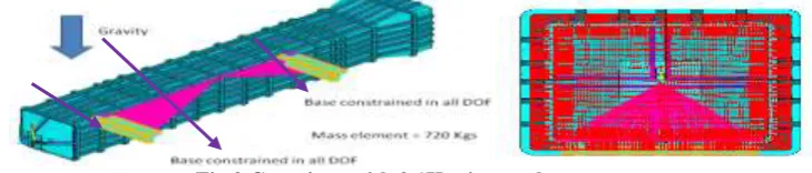
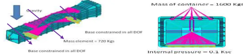
Objective: To perform structural analysis of a missile container by applying internal pressure of 0.1Ksc, to evaluate displacements and stresses developed in the container. Base is constrained in all DOF. Gravitational force is applied. Mass21 is used to distribute the weight of the missile over the bulk head, which supports the missile. Nitrogen is filled in the container to maintain low temperature for the missile sensors. Pressure of the nitrogen in the container is 0.1Ksc (0.689 Mpa). Pressure load is applied in the container. Below figure shows the container after applying structural load.
Fig.2 Container with 0.1Ksc internal pressure
IJEDR1704250
International Journal of Engineering Development and Research (
www.ijedr.org
)
1568
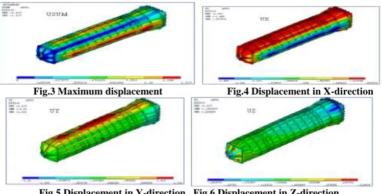
Fig.3 Maximum displacement Fig.4 Displacement in X-direction
Fig.5 Displacement in Y-direction Fig.6 Displacement in Z-direction
Linearised stress: Von Mises stress versus displacement graph is plotted for the path 1 to find linearised stress . Linearised stress at path 1 is 27.85 Mpa.
Fig.7 Linearised stress at path1 CASE2 – STACKING ANALYSIS
Objective: To perform structural analysis of a container, to evaluate displacements and stresses developed in the container under given load condition. Base is constrained in all DOF. Gravitational force is applied. Mass21 is used to distribute the weight of the missile over the bulk head, which supports the missile. While transporting the missiles, it is necessary to place the container one over the other. So, the container should withstand for the one more container and missile weight. That means, 1320 kg (total weight) is applied on the top of the container. Total weight is distributed on the top of the container by using the MASS21 element.
Internal pressure – 0.1 Ksc Fig.8 Container with internal pressure and stacking load
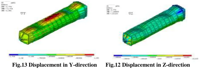
Displacement Plots:
Figure shows the displacement plots of the container for the internal pressure and stacking load. Max nodal displacements in X, Y and Z-direction are 0.045mm, 1.091mm and 0.211 mm respectively.
IJEDR1704250
International Journal of Engineering Development and Research (
www.ijedr.org
)
1569
Fig.13 Displacement in Y-direction Fig.12 Displacement in Z-direction
Linearised stress:
Von mises stress versus displacement graph is plotted for the path 1 to find linearised stress Linearised stress at path 1 is 66.5 Mpa.
Fig.13 Linearised stress at path 1
CASE 3– BRAKE ANALYSIS WITH 0.5G ACCELERATION
Objective: To perform structural analysis of a container, to evaluate displacements and stresses developed in the container due to 0.5g acceleration. Base is constrained in all DOF. Gravitational force is applied. Mass21 is used to distribute the weight of the missile over the bulk head, which supports the missile. Stacking load is also applied on the top of the container. 0.5g is applied as the braking force.
Fig.14 Container with internal pressure, stacking load and acceleration
Displacement Plots:
Figure shows the displacement plots of the container for the braking load 0.5g. Max nodal displacements are 0.05mm, 0.72mm and 0.12 mm in X, Y and Z-direction respectively.
Fig.15 Total displacement Fig.16 Displacement in X-direction
Fig.17 Displacement in Y-direction Fig.18 Displacement in Z-direction
Linearised stress:
Von mises stress versus displacement graph is plotted for the path 1 and 2 to find linearised stress . Linearised stress at path 1 and 2 is 87 Mpa and 24 Mpa respectively.
IJEDR1704250
International Journal of Engineering Development and Research (
www.ijedr.org
)
1570
Fig.19 Maximum stress at path 1 and 2Fig.20 Linearised stress plots at path 1 Fig.21 Linearised stress plots at path 2
CASE 4 – LIFTING ANALYSIS
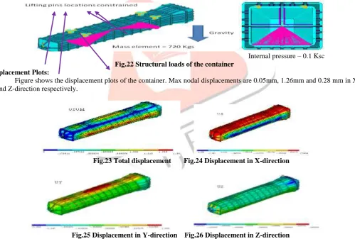
Objective: To perform structural analysis of a container, to evaluate displacements and stresses developed in the container, when lifting the container. Base is constrained in all DOF. Gravitational force is applied. Mass21 is used to distribute the weight of the missile over the bulk head, which supports the missile. Temporary lifting hooks made of forged alloy steel are provided to facilitate lifting of the container of the missile. As shown in figure lifting hooks are constrained in all DOF.
Internal pressure – 0.1 Ksc Fig.22 Structural loads of the container
Displacement Plots:
Figure shows the displacement plots of the container. Max nodal displacements are 0.05mm, 1.26mm and 0.28 mm in X, Y and Z-direction respectively.
Fig.23 Total displacement Fig.24 Displacement in X-direction
Fig.25 Displacement in Y-direction Fig.26 Displacement in Z-direction
Linearised stress:
As shown in figure Von mises stress versus displacement graph is plotted for the path 1 to find linearised stress. Linearised stress at path 1 is 29 Mpa.
Fig.27 Linearised stress at path 1 Path 1
Path2
IJEDR1704250
International Journal of Engineering Development and Research (
www.ijedr.org
)
1571
STRUCTURAL ANALYSIS OF MISSILE CONTAINER WITH 6mm THICKNESSCASE 1 – INTERNAL PRESSURE OF 0.1Ksc
Objective: To perform structural analysis of a missile container by applying internal pressure of 0.1Ksc, to evaluate displacements and stresses developed in the container. Base is constrained in all DOF. Gravitational force is applied. Mass21 is used to distribute the weight of the missile over the bulk head, which supports the missile. Nitrogen is filled in the container to maintain low temperature for the missile sensors. Pressure of the nitrogen in the container is 0.1Ksc (0.689 Mpa). Pressure load is applied in the container. Below figure shows the container after applying structural load.
Fig.28 Container with 0.1Ksc internal pressure
Displacement Plots:
Figure shows the displacement plots of the container for the internal pressure 0.1Ksc. Max nodal displacements are 0.87mm, 0.7mm and 0.16 mm in X, Y and Z-direction respectively.
Fig.29 Total displacement Fig.30 Displacement in X-direction
Fig.31 Displacement in Y-direction Fig.32 Displacement in Z-direction
Linearised stress:
Von mises stress versus displacement graph is plotted to find linearised stress at path 1 Linearised stress at path 1 is 21 Mpa.
Fig.33 Linearised stress at path 1 CASE 2 – STACKING ANALYSIS
Objective: To perform structural analysis of a container, to evaluate displacements and stresses developed in the container under given load condition. Base is constrained in all DOF. Gravitational force is applied. Mass21 is used to distribute the weight of the missile over the bulk head, which supports the missile. While transporting the missiles, it is necessary to place the container one over the other. So, the container should withstand for the one more container and missile weight. That means, 1600 kg (total weight) is applied on the top of the container. Total weight is distributed on the top of the container by using the MASS21 element.
IJEDR1704250
International Journal of Engineering Development and Research (
www.ijedr.org
)
1572
Displacement Plots:Figure shows the displacement plots of the container for the stacking analysis. Max nodal displacements are 1.01mm, 0.96mm and 0.13 mm in X, Y and Z-direction respectively.
Fig.35 Total displacement Fig.36 Displacement in X-direction
Fig.37 Displacement in Y-direction Fig.38 Displacement in Z-direction
Linearised stress:
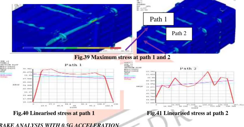
As shown in figure Von mises stress versus displacement graph is plotted for the path 1 and 2 to find linearised stress. Linearised stress at path 1 and 2 is 30 Mpa, 20 Mpa respectively.
Fig.39 Maximum stress at path 1 and 2
Fig.40 Linearised stress at path 1 Fig.41 Linearised stress at path 2
CASE 3– BRAKE ANALYSIS WITH 0.5G ACCELERATION
Objective: To perform structural analysis of a container, to evaluate displacements and stresses developed in the container due to 0.5g acceleration. Base is constrained in all DOF. Gravitational force is applied. Mass21 is used to distribute the weight of the missile over the bulk head, which supports the missile. Stacking load is also applied on the top of the container. 0.5g is applied as the braking force.
Fig.42 Container with internal pressure, stacking load and acceleration Displacement Plots:
Figure shows the displacement plots of the container for the braking load 0.5g. Max nodal displacements are 1.05mm, 1.02mm and 0.24 mm in X, Y and Z-direction respectively.
Fig.43 Total displacement Fig.44 Displacement in X-direction
Path 1
IJEDR1704250
International Journal of Engineering Development and Research (
www.ijedr.org
)
1573
Fig.45 Displacement in Y-direction Fig.46 Displacement in Z-direction
Linearised stress:
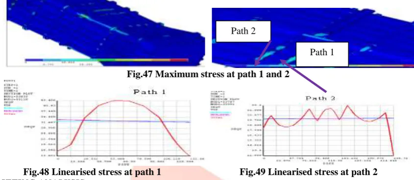
Von mises stress versus displacement graph is plotted for the path 1 and 2 to find linearised stress Linearised stress at path 1 and 2 is 31 Mpa and 20 Mpa respectively.
Fig.47 Maximum stress at path 1 and2
Fig.48 Linearised stress at path 1 Fig.49 Linearised stress at path 2
CASE 4 – LIFTING ANALYSIS
Objective: To perform structural analysis of a container, to evaluate displacements and stresses developed in the container, when lifting the container Base is constrained in all DOF. Gravitational force is applied. Mass21 is used to distribute the weight of the missile over the bulk head, which supports the missile. Temporary lifting hooks made of forged alloy steel are provided to facilitate lifting of the container of the missile. As shown in figure, lifting hooks are constrained in all DOF.
Internal pressure – 0.1 Ksc Fig.50 Container with structural loads
Displacement Plots:
Figure shows the displacement plots of the container for the lifting analysis. Max nodal displacements are 0.84mm, 0.89mm and 0.09 mm in X, Y and Z-direction respectively.
Fig.51 Total displacement Fig.52 Displacement in X-direction
Fig.53 Displacement in Y-direction Fig.54 Displacement in Z-direction Linearised stress:
As shown in figure Von mises stress versus displacement graph is ploted for the path 1 to find linearised stress. Linearised stress at path 1 is 20 Mpa.
Path 2
IJEDR1704250
International Journal of Engineering Development and Research (
www.ijedr.org
)
1574
Linearised stress = 20MpaFig.55 Linearised stress at path 1 V.CONCLUSIONS & SCOPE OF FUTURE WORK
Composite container was studied for 4 different cases with 4mm thickness and displacements, linearised stresses are tabulated below.
Nodal solutions of the missile container with 4mm thickness, for various analyses S.No. Description Ux(mm) Uy(mm) Uz(mm) Max
Stress(Mpa)
Linearised Stress(Mpa)
Case 1 Internal pressure 0.057 1.33 0.219 97.4 27.85
Case 2 Stacking analysis 0.045 1.091 0.211 129 68
Case 3 Braking analysis 0.05 1.1 0.12 170 87
Case 4 Lifting analysis 0.053 1.26 0.28 207 29
From the above table, we can conclude that braking analysis is the worst case. And by considering the material properties of E-glass/epoxy, the container is in failure state in the transverse direction. So, the design is not safe.Optimized the design in order to make the design safe, by increasing the thickness to 6mm and the results are as shown in below table.
Nodal solutions of the missile container with 6mm thickness, for various analyses
S.No. Description Ux(mm) Uy(mm) Uz(mm) Max Stress(Mpa)
Linearised Stress(Mpa)
Case 1 Internal pressure 0.87 0.7 0.16 52.7 21
Case 2 Stacking analysis 1.01 0.96 0.13 69.7 30
Case 3 Braking analysis 1.05 1.02 0.24 87 31
Case 4 Lifting analysis 0.84 0.89 0.09 128 20
From the above table, it is recommended that design is safe by increasing the thickness from 4mm to 6mm. SCOPE OF FUTURE WORK
As we are filling the container with Nitrogen gas, there is a chance of leakage. So, it is also necessary to analyze the container for leak-tight.
REFERENCES
[1] Dorothy S. Ng (1999). Structural Analysis of Storage Container, U.S. department of energy.
[2] Serena, Joseph M (1996). An On-Site Demilitarization Container for Unexploded Ordnance, Proc InstnMech Engrs Part C, No.717-729.
[3] Bob Matthews (1998). Applied Stress Analysis, Marcel Dekker, Inc London.
[4] Charles P. Haber (1976). Dynamic and Structural Analysis of Reusable Shipping & Storage Container for Encapsulated Harpoon Missile, Defense Technical Information Center, Europe.
[5] Cardinal, J. W., Dobosz, S. A., Pomerening, D. J (1987). Nondestructive Analysis of MK 607 Harpoon Missile container, Southwest research institute, 53-56.
[6] Federico A. Tavarez, Lawrence C. Bank, and Michael E. Plesha (2003). ACI structural journal, Analysis of Fiber-Reinforced Polymer Composite, Vol.36, No. 8, 941–962.
[7] Panos Y. Papalambros (1990). Journal of Mechanisms, Journal on Mechanical Design, Vol.40, No. 519-532 [8] Stephen W. Tsai (1996), Structural Behavior of Composite Materials, NASA, U.S.
[9] M.J Hinton, P.D Soden (1998). Predicting failure in composite laminates, 1001-1010. [10] A. Puck, H. Schürmann (1998). Failure Analysis of FRP Laminates, 1045-1067.
[11] Hwai-Chung Wu, Bin Mu, Kraig Warnemuende (2003). Failure Analysis of FRP Sandwich Bus Panels by Finite Element Method, 51-58.
[12] Swanson, R. S. (1997). Introduction to design and analysis with advanced composite materials. Prentice hall, Inc [13] Tuttle, M. E. (2004). Structural analysis of polymeric composite materials. Marcel Dekker Inc.
[14] Berthelot J. M. (1999). Composite materials: Mechanical behaviour and structural analysis. Springer – Verlag, New York.
[15] J.L. Curiel Sosa (1997). Advances in Composites Materials - Ecodesign and Analysis, Marcel Dekker, Inc London. [16] Ever J. Barbero (1988). An Inelastic Damage Model for Fiber Reinforced Laminates, International Fiber Science and Technology, 33-56.