A Passive Suppressing Jamming Method for FMCW SAR
Based on Micromotion Modulation
Jia-Bing Yan*, Ying Liang, Yong-An Chen, Qun Zhang, and Li Sun
Abstract—The frequency-modulated continuous wave (FMCW) synthetic aperture radar (SAR) has the properties of compact size, lightweight, low cost and low power dissipation, which provides great potential in the application of small platforms such as unmanned aerial vehicle (UAV). The imaging characteristics of rotary target for FMCW SAR are analysed based on the construction of echo signal model. Further, a passive suppressing jamming method for FMCW SAR based on micromotion modulation is proposed. This method makes use of rotary corner reflectors to form jamming strips in range and azimuth, and then the target screened is protected effectively. The choice of parameters of rotary corner reflectors is discussed in detail. Finally, some simulations are given to validate the theoretical derivation and the effectiveness of method.
1. INTRODUCTION
Compared to conventional pulse-synthetic aperture radar (pulse-SAR), frequency-modulated continuous wave (FMCW) SAR takes the advantages of compact size, lightweight, low cost and low power dissipation [1–3]. The “dechirp” processing is adopted in its receiver, where frequency mixing is conducted between echo signal and reference signal, and difference-frequency signal of narrow bandwidth is generated, thus reducing the requirements for video receiver, A/D sampling equipment and signal processing speed [4]. Meanwhile, the large time-bandwidth product of FMCW SAR makes it difficult for conventional reconnaissance aircraft to intercept and capture, owning favorable low probability of interception [5]. These features make it fairly applicable for military small-sized platform, which greatly improves the capability of SAR in military applications. Researches on FMCW SAR have been widely conducted in many countries [6–8], among them the MicroSAR system developed by the Brigham Young University in U.S. adopting FMCW SAR only weighs about 2 kg [8]. How to protect one’s own important targets from the enemy’s SAR recognition and improve one’s own anti-jamming ability of SAR has always been an important topic for jamming technology and SAR imaging research.
The passive suppressing jamming for SAR is mainly realized through placing jamming targets with large radar cross section (RCS) such as corner reflector and tin foil around the screened targets, thus submerging the screened targets in strong side lobe of jamming targets. Passive suppressing jamming for SAR based on micromotion modulation further adopts the rotation of corner reflectors to form jamming stripes in range and azimuth. Some researches focused on passive and active jamming method for SAR based on micromotion modulation has appeared in the past few years [9, 10]. In [9] a new passive barrage jamming method for SAR is proposed using the rotating angular reflectors, and the selection of the key parameter of the rotating angular reflectors is discussed in detail. Ref. [10] proposed an active jamming method for SAR based on micromotion. Furthermore, in [11] and [12] the SAR imaging characteristics of rotating targets are analyzed, which can also provide a reference for the jamming method based on micromotion.
Received 28 April 2015, Accepted 13 April 2016, Scheduled 20 April 2016 * Corresponding author: Jia-Bing Yan ([email protected]).
However, the aforementioned researches mainly studied the jamming method for pulse-SAR, while the passive jamming method for FMCW SAR based on micromotion modulation has not been studied. To guarantee low transmission power, FMCW SAR signal usually adopts long pulse duration, therefore the change of range with the continuous movement of carrier aircraft should be considered in the FMCW SAR signal processing, which is different from the traditional way of pulse-SAR signal processing. This distinction makes the passive jamming method variational, and some new passive jamming methods should be studied.
In this paper, the model of rotary target’s echo signal for FMCW SAR is established. The jamming characteristics of rotary target for FMCW SAR imaging is analyzed first, and then the parameter setting of rotary corner reflectors is discussed in detail. In this way, a passive suppressing jamming method for FMCW SAR adopting rotary corner reflectors is proposed. Finally, the simulation results verified the effectiveness of the proposed method.
2. JAMMING SIGNAL MODEL
The geometry model of FMCW SAR is illustrated in Fig. 1, where the carrier aircraft moves along the
x axis direction with speed v and flight heighth. Suppose that there is a rotary target pointP in the azimuth center, with rotary radiusr, rotary frequencyfP (angular frequencyωP = 2πfP), initial phase
θ0 and distance R0 from the rotation center to radar platform.
The long duration of pulse makes the conventional “stop and go” approximation fail for FMCW SAR signal processing, and the change of range caused by the continuous movement of platform should be considered. Therefore, the instantaneous slant distance between rotary point P and carrier aircraft can be represented as
R(t)≈R0+rcos (ωPt+θ0) +
(vt−rsin (ωPt+θ0))2 2R0
(1)
Among them,t=tk+tm represents the total time, andtk,tm represent fast time and slow time, respectively. Further expand Eq. (1) as
R(t)≈R(tm)−ωPrsin (ωvtm+θ0)tk+
v2tm
R0
tk (2)
where
R(tm)≈R0+rcos (ωPtm+θ0) +
(vtm−rsin (ωPtm+θ0))2 2R0
(3)
In Eq. (2), the second term is the change of range in pulse duration caused by the rotary point, and the third term is the Doppler shift caused by continuous movement of aircraft. In the subsequent
0 θr
0 R
P ω O
v z
x
y h
P the flight pat
h of aircraft
Y
processing, the Doppler shift can be compensated by constructing compensation function in azimuth Doppler domain.
After the “dechirp” processing of echo signals, the difference-frequency signal can be expressed by
s(tk, tm) =σP exp ( −j ( 4πµ c (
tk− 2Rref
c
)
R∆(t) + 4π
λ R∆(t)
)) exp
(
j4πµ c2 R
2 ∆(t)
)
(4)
where σP is the scattering coefficient of rotary point P, c the speed of light, λ the wavelength and
R∆(t) = R(t)−Rref (Rref the reference distance). The last term of Eq. (4) is residual video phase (RVP), whose compensation can be achieved in azimuth Doppler domain [8]. In this paper, the effect of RVP is ignored in the subsequent analysis. Combined with Eq. (2), we can get
s(tk, tm) = σPexp (
−j
( 4πµ
c R∆(tm)tk−
4π
λ ωPrsin (ωvtm+θ0)tk
))
·exp (
−j4π
λ R∆(tm)
) exp
( −j4πv
2t m λR0 tk ) (5)
where the first term is range imaging factor; the second term is azimuth imaging factor; the third term is the Doppler shift caused by continuous movement of carrier aircraft, a coupling term of fast time and slow time. The compensation of Doppler shift should be completed in azimuth Doppler domain. Conduct Fourier transform in terms oftmto Eq. (5) and construct Doppler shift compensation function as
HD(tk, fa) = exp (−j2πfatk) (6) where fa represents azimuth Doppler frequency. After the Doppler shift compensation, taking the inverse Fourier transform in terms offa, it can be obtained that
s(tk, tm) =σP exp (
−j
( 4πµ
c R∆(tm)tk−
4π
λωPrsin (ωvtm+θ0)tk
)) ·exp
( −j4π
λR∆(tm)
) (7)
3. JAMMING CHARACTERISTICS ANALYSIS AND PARAMETER DESIGN
In this paper, take the Range-Doppler (R-D) algorithm as an example, the jamming characteristics of rotary target for FMCW SAR is analyzed. Conduct distance compression processing first, that is to conduct Fourier transform in terms of fast time to Eq. (7) and get
S(fr, tm) = σPsinc (TP(fr+ψ(tm))) exp (
−j4πR(tm) λ
)
(8)
ψ(tm) = 2µ
c R∆(tm)−
2
λωPrsin (ωvtm+θ0)
= 2µ
c
(
R0−Rref +rcos (ωPtm+θ0)−
ωPrfc
µ sin (ωvtm+θ0)
)
= 2µ
c (R0−Rref +Acos (ωPtm+φ)) (9)
whereA=√r2+a2,a=ω
Prfc/µ,φ= arctan (a/r) +θ0 andfcis the carrier frequency. WhenA > ρr, the rotary point appears in the form of sine (cosine) term in range-slow time spectrogram, and the range shift A (also called equivalent rotary radius) is related to not only the actual rotary radius but also parameters such as rotary frequency and carrier frequency. In order to achieve passive suppressing jamming, the parameters of corner reflectors are usually set to make the equivalent rotary radius cover a certain extent of range and form jamming stripes. Fig. 2 illustrates the relation curve between rotary frequency and equivalent rotary radius, where the carrier frequency of FMCW SAR is 35 GHz, the bandwidth 300 MHz, the pulse repetition time 1 ms and the corresponding pulse repetition frequency (PRF) 1000 Hz. It can be seen that with the increase of rotary frequency, the equivalent rotary radius increases accordingly.
0 2 4 6 8 10 0
5 10 15 20 25 30
Frequency/Hz
R
an
g
e/
m
r = 0.1m
r = 0.3m
r = 0.5m
r = 0.8m
r = 1m
Figure 2. The relation curve between rotary frequency and equivalent rotary radius.
m
r
/m
-500 0 500
0.1
0.2
0.3
0.4
0.5
Figure 3. The Amplitude ofJm(B).
After azimuth compression, the two-dimensional imaging result of the point can be obtained. However, due to the effect of rotation, there is sinusoidal phase modulation in the echo signal. After azimuth compression, the echo signal can be expressed by
S(fr, tm) =σPsinc (TP (fr+ψ(tm)))
∞
∑
m=−∞
Jm(B) sinc (
tm+
mfP
ka )
(10)
whereka =−2v2 /
λR0 is the azimuth Doppler Chirp rate,B = 4πr/λ, andJm(B) is Bessel function of the first kind [12], whose expression is
Jm(B) = 1 2π
∫ π
−π
exp (−Bcos (x+θ0))ejmxdx (11)
According to Eq. (10), after azimuth compression the echo signal of rotary point target is the superposition of a series of narrow pulse signals. The interval between adjacent narrow pulses is
∆t= fP
ka
(12)
The value domain of the number of narrow pulses, m, is determined by Bessel function Jm(B). Conduct variable substitution x=−2πx′ on Eq. (11), we can get
Jm(B) = 1 2π
∫ π
−π
exp(−Bcos(−2πx′+θ0 ))
e−j2πmx′d(−2πx′)
= − ∫ π
−π
exp(−Bcos(−2πx′+θ0 ))
e−j2πmx′dx′ (13)
To avoid confusing, Eq. (13) is still written as
Jm(B) =− ∫ π
−π
exp (−Bcos (−2πx+θ0))e−j2πmxdx (14)
According to Eq. (14), Jm(B) is actually Fourier transform of a sinusoidal frequency modulation signal, whose bandwidth is the value domain of m, that is
m∈(−B, B) (15)
According to the above analysis of rotary target’s jamming characteristics for FMCW SAR, rotary corner reflectors can be used to implement passive suppressing jamming through generating two-dimensional jamming strips in range and azimuth. The jamming in azimuth is mainly achieved by narrow pulses formed after the azimuth compression of rotary corner reflector echo signal, where the interval of narrow pulses determines the jamming performance. In order to ensure that narrow pulses can cover the entire azimuth, i.e., ∆x < ρa, whereρa is the azimuth resolution, the rotary frequency of corner reflector should satisfy
fP
kaP RI ≤ 1
kaTsP RI
, i.e., fP ≤ 1
Ts
(16)
The range of azimuth jamming is determined by the interval and number of narrow pulses. According to the interval of narrow pulse, the number of narrow pulses needed to form La range of jamming in azimuth is
km≥
La ∆x =
LafPTs
ρa
(17)
whereTs is synthetic aperture time. Since the number of narrow pulses satisfies
km= floor{2B}= floor{8πr/λ} (18) where floor{·}means to round down. Then the rotary radius can be determined by
r≥ kmλm
8π (19)
With rotary frequency and rotary radius fixed, the equivalent rotary radius can be written by
A=√r2+a2. With range jamming extentL
r, the number of rotary corner reflectorsknshould satisfy
kn≥
Lr
2A (20)
4. SIMULATION AND ANALYSIS
Suppose that the carrier frequency of FMCW SAR is 35 GHz, the bandwidth 300 MHz, the pulse duration 1 ms and the sampling frequency 1.25 MHz. FMCW SAR is working in side-looking mode. The speed of aircraft is 200 m/s, the distance from the center of target area to aircraft 5 km, the synthetic aperture time 0.21 s, and range and azimuth resolution are both 0.5 m.
4.1. Analysis of Jamming Characteristics
The jamming characteristics of rotary target are simulated and analyzed first, where the parameter settings of rotary point are shown in Table 1.
Table 1. Parameter settings of rotary corner reflectors.
Corner reflector index 1 2 3 4 5
Parameter setting 1
r (m) 0.01 0.02 0.03 0.04 0.05
fP (Hz) 5 5 5 5 5
location (km) (0, 4.9) (0, 4.95) (0, 5) (0, 5.05) (0, 5.1)
Parameter setting 2
r (m) 0.2 0.2 0.2 0.2 0.2
fP (Hz) 1 2 5 20 40
location (km) (0, 4.9) (0, 4.95) (0, 5) (0, 5.05) (0, 5.1)
than range resolution, thus forming line along with the azimuth direction in the imaging results. The rotary frequencies of 5 corner reflectors are the same, which brings the same narrow pulse interval in imaging results. Meanwhile, with the increase of rotary radius, the number of narrow pulses increase accordingly, which means more jamming strips in imaging. Under the condition of parameter setting 2, with different rotary frequencies and the same rotary radius of corner reflectors, the equivalent rotary radiuses are different, which are 0.25 m, 0.35 m, 0.76 m, 2.94 m and 5.87 m, respectively. Number 1, 2 corner reflectors’ equivalent rotary radiuses are still smaller than range resolution; therefore, their imaging results are represented as lines along the azimuth direction, while those of numbers 3–5 are larger than range resolution, which brings strips along the azimuth direction in imaging.
R
an
g
e/
m
Azimuth/m
-50 0 50
-150 -100 -50 0 50 100 150
R
an
g
e/
m
Azimuth/m
-40 -20 0 20 40
-100 -50 0 50 100
(a) (b)
Figure 4. Analysis of jamming characteristics. (a) Parameter setting 1. (b) Parameter setting 2.
R
an
g
e/
m
Azimuth/m
-15 -10 -5 0 5 10 15
-20 -15 -10 -5 0 5 10 15 20
-15 -10 -5 0 5 10 15
-15 -10 -5 0 5 10 15
R
an
g
e/
m
Azimuth/m
(a) (b)
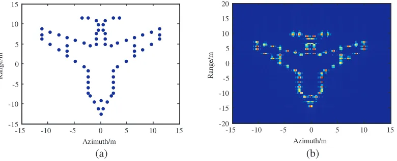
Figure 5. The model of the screened target. (a) Airplane model of 66 scatterers. (b) Two-dimensional imaging results.
4.2. Analysis of Jamming Performance
Take airplane model of 66 scatterers as the model of screened target, as shown in Fig. 5(a), and whose two-dimensional imaging result without jamming is shown in Fig. 5(b).
Table 2. Parameter settings of rotary corner reflectors.
Corner reflectors
Parameter setting 1
Parameter setting 2
Parameter setting 3
Parameter setting 4
r (m) 1.62 1 1.05 1.35
fP (Hz) 10 8 5 2
number of reflectors 1 2 3 5
R
an
g
e/
m
Azimuth/m
-15 -10 -5 0 5 10 15
-20 -15 -10 -5 0 5 10 15 20
R
an
g
e/
m
Azimuth/m
-15 -10 -5 0 5 10 15
-20 -15 -10 -5 0 5 10 15 20
R
an
g
e/
m
Azimuth/m
-15 -10 -5 0 5 10 15
-20 -15 -10 -5 0 5 10 15 20
R
an
g
e/
m
Azimuth/m
-15 -10 -5 0 5 10 15
-20 -15 -10 -5 0 5 10 15 20
(a) (b)
(c) (d)
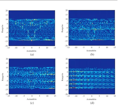
Figure 6. Imaging results with jamming implemented. (a) Parameter setting 1. (b) Parameter setting 2. (c) Parameter setting 3. (d) Parameter setting 4.
The parameter settings can all basically make range jamming strips cover the entire screened target. With the rotary frequency decreasing, the interval of narrow pulses formed in azimuth decreases accordingly, thus creating better azimuth jamming performance. With parameter setting 4, the screened airplane is totally submerged in the noise of corner reflector echo signal. The signal-to jamming (SJR) ratio are−11.22 dB, −14.23 dB,−15.99 dB and−18.19 dB, respectively.
5. CONCLUSION
Due to the FMCW SAR’s own superiority, it will definitely catch more and more attention, and the jamming to FMCW SAR will increasingly become a hotspot in research of jamming technology. In this paper, the jamming characteristics of rotary target for FMCW SAR is analyzed, and a passive suppressive jamming method for FMCW SAR based on micro motion modulation is proposed. This method makes use of the rotary corner reflectors to form jamming strips in range and azimuth, thus realizing effective protection of the screened targets. The simulations validate the theoretical derivation and the effectiveness of the proposed passive supressing jamming method.
ACKNOWLEDGMENT
This work was supported in part by the National Natural Science Foundation of China under Grant 61471386 and the Coordinator innovative engineering project of Shaanxi province under Grant 2015KTTSGY04-06.
REFERENCES
1. Meta, A. and P. Hoogeboom, “Development of signal processing algorithms for high resolution airborne millimeter wave FMCW SAR,” Proc. IEEE Int. Radar Conf.’05, 326–331, Arlington, U.S.A, 2005.
2. Meta, A., P. Hoogeboom, and L. P. Ligthart, “Signal processing for FMCW SAR,” IEEE
Transactions on Geoscience and Remote Sensing, Vol. 45, No. 11, 3519–3532, 2007.
3. Wang, R., Y. Luo, Y. Deng, et al., “Motion compensation for high-resolution automobile FMCW SAR,” IEEE Geoscience and Remote Sensing Letters, Vol. 10, No. 5, 1157–1161, 2013.
4. Liu, Y., Y. Deng, R. Wang, et al., “Efficient and precise frequency-modulated continuous wave synthetic aperture radar raw signal simulation approach for extended scenes,” IET Radar Sonar
and Navigation, Vol. 6, No. 9, 858–866, 2012.
5. Adve, R., “Bistatic FMCW SAR signal model and imaging approach,” IEEE Transactions on
Aerospace and Electronics, Vol. 49, No. 3, 2017–2028, 2013.
6. Edrich, M., “Design overview and flight test results of the miniaturized SAR sensor MISAR,”Proc.
EuRAD’04, 205–208, Amsterdam, The Netherlands, 2004.
7. Duersch, M. I., “BYU. Micro-SAR: A very small low-power LFM-CW synthetic aperture radar,” Brigham Young University, 2004.
8. Wang, R., O. Loffeld, H. Nies, et al., “Focus FMCW sar data using the wavenumber domain algorithm,” IEEE Transactions on Geoscience and Remote Sensing, Vol. 48, No. 4, 2109–2118, 2010.
9. Sun, G.-C., X.-R. Bai, F. Zhou, et al., “A new passive barrage jamming method for SAR,”Journal
of Electronics &Information Technology, Vol. 31, No. 3, 610–613, 2009 (in Chinese).
10. Wu, X.-F., D.-H. Dai, X.-S. Wang, et al., “A novel method of active jamming for SAR based on micro motion modulation,”Acta Electronica Sinica, Vol. 38, No. 4, 954-958, 2010 (in Chinese). 11. Wu, X.-F., Y. Liu, X.-S. Wang, et al., “Analysis of SAR imaging characteristics of targets with
rotational micro-motion,”Journal of Astronautics, Vol. 31, No. 4, 1181–1189, 2010 (in Chinese). 12. Rigling, B. D., “Image-quality focusing of rotary SAR targets,”IEEE Geosci. Remote Sens. Lett.,