S tr u c tu r in g D iv e r s e ly D e s ig n e d S o ftw a re
W a n d e r le y L o b ia n co J u n io r
March, 1994
D e p a r t m e n t o f C o m p u t e r Sc i e n c e
Un i v e r s i t y C o l l e g e Lo n d o n
Un i v e r s i t y o f Lo n d o n
This thesis is subm itted to the U niversity of London in
p artial fulfilment of the requirem ents for th e degree of
ProQuest Number: 10046121
All rights reserved
INFORMATION TO ALL USERS
The quality of this reproduction is dependent upon the quality of the copy submitted.
In the unlikely event that the author did not send a complete manuscript and there are missing pages, these will be noted. Also, if material had to be removed,
a note will indicate the deletion.
uest.
ProQuest 10046121
Published by ProQuest LLC(2016). Copyright of the Dissertation is held by the Author.
All rights reserved.
This work is protected against unauthorized copying under Title 17, United States Code. Microform Edition © ProQuest LLC.
ProQuest LLC
789 East Eisenhower Parkway P.O. Box 1346
A b s tr a c t
There are a num ber of com puter control systems in which a fault in the soft
ware can endanger hum an hves or lead to substantial financial loss. Software fault-
tolerance provides tolerance to residual design faults in the software by means of
diversely designed versions which comply w ith a single specification. This has proved
to be an effective way of increasing software rehabihty. However, there are designers
who hesitate to adopt this approach because of th e additional cost of producing and
integrating diversely designed software and assessment algorithms. Hence, guide-
Hnes are needed for stru ctu rin g fault-tolerant software so th a t the tim e and cost
of developing and integrating m ultiple versions and assessment com ponents are re
duced.
The m ain contribution of this research is to propose and justify a framework for
structuring fault-tolerant software based on reusable components th a t encapsulate
d a ta and com m unicate by message exchange via indirect addressing. Reusable com
ponents allow for a reduction in th e cost of system, development, as fewer specially
tailored modules are needed. Moreover, th e reliabifity of reusable components have
been observed in the field.
The framework provides a tran sp aren t filter between th e diversely designed ver
sions and th e modules th a t com m unicate w ith them . Therefore, fault-tolerant soft
ware modules are interchangeable w ith functionally equivalent com ponents th a t do
not tolerate residual design faults. As a result, software com ponents do not need to
have special interfaces either to com m unicate w ith fault-tolerant modules or to be
configured as diversely designed versions.
The framework caters for the realisation of fault-tolerant modules based on well-
known software fault-tolerance techniques, such as; compensation, exception han
dling, recovery blocks, and n-version programming. In addition, it extends their
T o
my wife Ter ezi nha,
my p a r e n t s W a n d er l e y a n d Nelma, my g r a n d p a r e n t s Q u i t o and Dinah,
A c k n o w le d g e m e n ts
I am deeply grateful to my supervisor, Professor Steve R. W ilbur, for his guidance and advice. His support has been fundam ental to my research. His comments and his ideas have been of great value throughout the developm ent of this work.
I am thankful to Conselho Nacional de Desen vol vimento Cientffico e Tecnologico (C N Pq, grant No. 202167/89-5) for their financial support. In particular, I would Hke to th an k Dr. Nelson Prugner for being always very helpful.
Special thanks are due to Ben Bacarisse, Tony Ballardie, Stephen Hailes, David Lee, David P a rro tt, Mian Wei, and Russel W inder, whose comments and suggestions have contributed significantly to improve this work.
May I also express my gratitu d e to Air-Chief-Marshal Socrates M onteiro, ESCA C om puting Systems (Brazil), and th e Civil Aviation A ut hority- C A A (U .K .) for their valuable contributions to the experim ent in air traffic control carried out in this research. I wish to than k Dr. Stephen Hailes for his co-supervision of th e project and J. Asiedu, A. Dove, L. Du, C. Harris, A. M ahmood, and N. Stchedroff for their com petent work in the specification, design, im plem entation, and docum entation of th e system.
To my parents W anderley and Nelma, and to m y brother, Luis Eduardo, I will be eternally in debt for their love, altruism , incentive, and dedication. I could not have grown up in a b e tte r environm ent th a n th e one they provided me with.
To my parents-in-law, Mario and Ivone, I wish to th an k not only for their love and support, b u t also for having given me th e most im p o rtan t person in my fife, my wife Terezinha.
I wish to express my g ratitu d e to Capello Ivo and W anda FolhadeUa, who were very special to me, for all th eir love and care.
I am very thankful to m y brother-in-law Mario R oberto, m y sister-in-law Helena, and my nephew A ndré for making us feel a t home in London,
Words are too weak to express how m uch I own to my wife Terezinha. She has given me all support, incentive, dedication th a t I needed. Above all, she has given me her love, more th an I could ever dream of. I wish to th an k my wife for loving me so much and for staying by my side at all times in my life.
C o n te n ts
1 In tr o d u c tio n 20
1.1 M ain Goals ...22
1.2 Plan of the T h e s is ...23
2 R e v ie w on S o ftw a re F a u lt-T o lera n ce 27 2.1 Concepts and T e rm in o lo g y ... 28
2.2 Classification of Fault-Tolerance T e c h n iq u e s ...31
2.3 Techniques Based on Identical R e p h c a s ... 32
2.3.1 Passive R e p h c a tio n ... 32
2.3.2 Active Replication ... 34
2.4 Techniques Based on Design D iv e rsity ... 35
2.4.1 C o m p e n sa tio n ... 36
2.4.2 Exception H a n d fin g ... 36
C o n te n ts 6
2.4.4 C o n v e rsa tio n s ... 41
2.4.5 N-Version P r o g r a m m in g ... 44
2.5 S u m m a r y ... 50
3 S o ftw a re C o m p o n e n ts 51 3.1 Black Box Classification of Software M o d u le s... . 51
3.2 E stim ation of Software R e lia b ility ...54
3.3 Software Development P r o c e s s ... 56
3.4 D iv e rs ity ... 58
3.5 Selective and T ransparent F a u lt- T o le ra n c e ... 60
3.6 S u m m a r y ... 63
4 M o d e llin g F a u lt-T o lera n t S o ftw a re C o m p o n e n ts 64 4.1 Framework O u t l i n e ... 65
4.2 Assessment ...66
4.2.1 O u tp u t Assessment S tr a t e g ie s ... 67
4.2.2 In p u t V alidation ...70
4.2.3 S tructuring Principles ...71
4.3 E rror H a n d l i n g ... 72
C o n te n ts 7
4.3.2 Internal Error R e c o v e r y ... 75
4.3.3 Error Handling M o d u l e s ... 75
4.4 C o-ordination C o m p o n e n t...77
4.4.1 Assessment O rder of O u t p u t s ... 78
4.4.2 Tem poral Sequencing of the V e r s io n s ...79
4.5 S u m m a r y ...80
5 A S o ftw a re F a u lt-T o lera n ce Fram ew ork 81 5.1 Suitable Program m ing P a r a d ig m s ... 82
5.2 Framework R e a lis a tio n ... 84
5.2.1 Controller F u n c tio n in g ... 87
5.3 Protocols ... 88
5.3.1 Input Validation P r o t o c o l ...89
5.3.2 O u tp u t Validation Protocol . ...90
5.3.3 Error Handling P r o t o c o l ...98
5.4 Errors in th e Time Domain ... 101
5.4.1 Tim e-out Clauses in Communications w ith th e Versions . . . . 104
5.5 Late M essa g e s...105
C o n te n ts 8
5.6 M ulti-Port SoFT M o d u l e s ... 109
5.6.1 Synchronisation of the M ono-port C o n t r o l l e r s ...I l l 5.7 S u m m a r y ... 114
6 A n a ly sis o f th e S o F T M o d e l 117 6.1 Basic C o n fig u ra tio n s ... 117
6.2 Traditional Software Fault-Tolerance Techniques in S o F T ...126
6.2.1 C o m p e n sa tio n ... 127
6.2.2 Exception H a n d h n g ...128
6.2.3 Recovery B lo c k s... 130
6.2.4 N-Version P r o g r a m m in g ... 130
6.3 Complexity of Messages in SoFT M o d u l e s ... 132
6.3.1 Complexity of Messages at Each Controller P o r t ... 132
6.3.2 Global Complexity of M e s s a g e s ...134
6.4 Availabihty Is s u e s ... 139
6.5 T e s tin g ... 140
6.6 S u m m a r y ...141
C o n te n ts 9
7.2 Im plem entation of the C o n t r o l l e r ...146
7.3 Numeric A n a ly s is ...148
7.4 S u m m a r y ...154
8 A n A p p lica tio n in A ir Traffic C o n tro l 155 8.1 O b je c tiv e s ...155
8.2 The E x p e rim e n t...157
8.2.1 Executive O v erv iew ...157
8.2.2 Technical D e sc rip tio n ... 158
8.3 Incorporation of Software Fault-Tolerance ... 162
8.3.1 Plan V a lid a tio n ... 162
8.3.2 Route E x t r a c t i o n ... 164
8.3.3 Approaching L is ts ... 165
8.3.4 Collision W a rn in g ... 167
8.4 Conclusions of the E x p e rim e n t... 169
8.5 S u m m a r y ...170
9 L im ita tio n s and R e la te d W ork 171 9.1 N on-Transparent Error R e c o v e r y ... 171
C o n te n ts 10
9.1.2 Recovery by Assessing Internal S t a t e s ... 173
9.2 Versions with Non-coincident E xternal States ... 175
9.3 Related W o r k ... 178
9.3.1 Canonical Recovery B lo c k s... 178
9.3.2 DEDIX ... 180
9.3.3 C i r c u s ... 182
9.3.4 Fault Tolerant Module ( F T M ) ... 183
9.4 S u m m a r y ...185
10 C o n clu sio n s 186 10.1 The SoFT M o d e l ...188
10.2 Configurations of the SoFT M o d e l... 190
10.3 Final R e m a rk s... 192
10.4 F uture R e s e a rc h ...193
A S p ec ifica tio n o f th e S o F T M o d e l 195 A .l Definition of the M o d e l...196
A .2 The Controller ...199
A .2.1 The Token A dm inistrator ... 218
C o n te n ts 11
A .3.1 An External M o d u l e ...219
A .3.2 A V e r s i o n ...220
A.4 O ther C o m p o n e n ts ...221
A .4.1 An In p u t Validation M o d u le ...221
A.4.2 A Conformity T e s t ... 222
A .4.3 A M ajority V o t e r ... 223
A .4.4 A Com pensation M o d u le ... 225
A .4.5 An Error Handling M o d u le...225
A .5 Sum m ary of Message T y p e s ...225
A .6 N o ta tio n ... 229
A .6.1 S e m a n tic s ...229
A .6.2 S y n ta x ... 234
B C o m p le x ity E v a lu a tio n o f S oF T M essa g es 238 B .l C o n su m e rs... 239
B.2 P r o d u c e r s ... 240
B.3 C l i e n t s ...242
B.4 S e rv e rs ...247
C o n te n ts 12
B.4.2 Sequential S erv ers... 252
C P O P E : a P o r t-O rie n ted P ro g ra m m in g E n v ir o n m e n t 257 C l Prim itive C o m p o n e n ts ... 257
C.2 The Kernel ... 259
C.3 C luster C o m p o n e n ts ... 260
C.3.1 Composite Components ... 262
C.3.2 Communication B u s e s ... 263
C.4 P r im iti v e s ...264
C.4.1 Configuration P r im itiv e s ...265
C.4.2 Communication P r im itiv e s ... 268
C.5 E x a m p l e s ...272
C.6 S u m m a r y ...279
D P r in c ip le s o f A ir Traffic C o n tro l 280 D .l M ain Air Traffic Control A c t i v i t i e s ... 281
D.1,1 Analysis of Flight P l a n s ...282
D.1.2 Analysis of R adar D a t a ... 284
C o n te n ts 13
G lo ssa r y 287
L ist o f F ig u res
1.1 Illustration of a Fault-Tolerant Software M o d u le ...22
2.1 Exam ple of a System S t r u c t u r e ...29
2.2 Fram ework for an Ideal Exception-based Fault-tolerant Com ponent . 37 2.3 Exam ple of a Recovery B l o c k ...39
2.4 The Domino E f f e c t ...42
2.5 Processes Transactions via C o n v ersa tio n s... 43
2.6 G eneral Triple-M odular Reduncancy (TM R) D ia g r a m ...44
2.7 An Exam ple of Two Groups Sending Messages to a T h i r d ... 49
2.8 Hierarchical R epresentation of Software Fault-Tolerance Techniques . 50 3.1 Black Box Model of a Software M o d u le ... 52
3.2 Black Box Model Classification as to its Inputs and O u tp u ts . . . 53
3.3 Use of Diversity in the Phases of th e Software Development Process . 61
L ist o f F ig u res 15
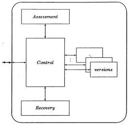
4.1 O utline of a Software Fault-Tolerant C o m p o n e n t... 67
4.2 Generic Configuration of the Assessment S u b s y s te m ... 72
4.3 Diagram of a Fault-Tolerant Assessment Component ... 73
5.1 A SoFT M o d u le ... 84
5.2 Controller Interaction with th e Input Validation M o d u l e ...89
5.3 Exam ple of an Input Validation Module ... 90
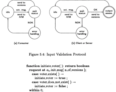
5.4 In p ut Validation Protocol ...91
5.5 Initiation of a New Round of V o tin g ... 91
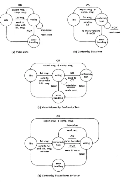
5.6 Voter Protocol w ith Static O u tpu t Assessment O r d e r , . . 93
5.7 Voter Protocol w ith Dynamic O utput Assessment O r d e r ... 94
5.8 Controller Com m unication with the V o t e r ...95
5.9 Exam ple of a M ajority V o te r ... 96
5.10 Controller Interaction w ith th e Conformity T e s t ... 97
5.11 Exam ple of a Conformity T e s t ... 97
5.12 O u tp u t Assessment P r o t o c o l s ... 99
5.13 Controller Interaction with the Compensation Modules ... 100
5.14 Exam ple of a Com pensation Module ... 100
L ist o f F ig u res 16
5.16 Exam ple of an Error Handling M o d u l e ... 102
5.17 A Client SoFT Module with a M atching V o t e r ... 109
5.18 Simplified A rchitecture of a Filter SoFT M o d u le ...112
5.19 Controller Algorithms for Token Allocation and R e le a se ...113
5.20 Algorithm of th e Token A d m in is tr a to r ... 114
5.21 Mono-controUers - Token A dm inistrator Simplified D i a g r a m ...115
6.1 SoFT Framework for A n a ly s is ... 118
6.2 G eneral S tructure of a Producer SoFT M o d u le ... . 120
6.3 High Level Specification of a Producer C o n t r o l l e r ...120
6.4 G eneral Structure of a Consumer SoFT M o d u l e ...121
6.5 High Level Specification of a Consumer C o n tro lle r...121
6.6 G eneral S tructure of a Client SoFT M o d u l e ... 122
6.7 High Level Specification of a Client C o n tr o lle r... 123
6.8 G eneral Structure of a Server SoFT M o d u l e ...124
6.9 High Level Specification of a Server C o n tro lle r... 125
6.10 Exam ple of a SoFT Server based on C o m p e n s a tio n ...128
6.11 Exam ple of a SoFT Server based on E x c e p tio n ...129
L ist o f F ig u res
6.13 Example of a SoFT Server based on N-version P r o g r a m m in g ...131
7.1 Module with a Monolithic Fault-Tolerance C o m p o n e n t ... 144
7.2 Possible Configurations of SoFT Com ponents ... 147
8.1 Diagram of the Air Traffic Control S y s t e m ...159
8.2 Air Route C hart of The United K in g d o m ... 160
8.3 Fault-Tolerant Configuration of Module Plan ...164
8.4 Fault-Tolerant Configuration of Module S c h e d u le r... 166
8.5 Fault-Tolerant Configuration of Module C o l l i s i o n... 168
9.1 Normal and Error Recovery Codes in a Single Com ponent . . . .1 7 3 9.2 External Assessment of the Internal S tate of a Module ... 174
9.3 A SoFT Module Assessing th e Internal States of SoFT Versions . . . 176
9.4 Example of a SoFT Client based on th e Recovery Block A pproach . . 180
9.5 Equivalent Server Configurations in th e FT M and SoFT Models . . . 184
10.1 The SoFT F r a m e w o r k ...187
10.2 Possible Configurations of SoFT Com ponents (r e p r o d u c tio n ) ... 191
A .l A Server SoFT Module in a Client-Server C o n fig u ratio n ... 197
L ist o f F ig u res 18
C .l Ports and L i n k s ... 259
C.2 Example of a Simple Client-Server Configuration in P O P E ...261
C.3 Example of Composite C o m p o n e n ts ... 263
C.4 Example of Components Linked via a Com m unication B u s ... 264
C.5 Diagram of a Client-Server-Alarm C o n fig u ra tio n ... 273
C.6 Example of a Configuration Component ... 274
C.7 Exam ple of a Server C o m p o n e n t... 275
C.8 Example of a Client C o m p o n e n t... ... . 277
C.9 Example of a Consumer C o m p o n en t...278
L ist o f T a b les
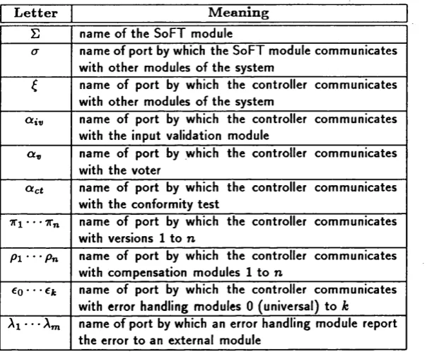
5.1 Greek Letters used in SoFT M o d u l e s ... 86
5.2 Acronyms used in SoFT M o d u l e s ...86
6.1 SoFT Configurations for Message Complexity Analysis ... 136
6.2 Message Com plexity Analysis for n = 3 and A; = 0 ... 138
7.1 SoFT Controller Function S i z e s ...150
7.2 SoFT Controller Function U tilis a tio n ...151
7.3 Sizes of th e Possible Configurations of the SoFT C o n tro lle r ...152
7.4 Specific SoFT Controllers Grouped by Role and Version Execution M o d e ... 153
C h a p te r 1
I n tr o d u c tio n
There are a num ber of critical applications where a failure in th e com puter control
system can endanger hum an Hves or lead to substantial financial loss. For a long
tim e, fault-tolerance techniques have been used to cope w ith hardw are faults [Car87].
More recently, designers have also been concerned w ith residual faults in th e software
which manifest themselves only when the systems are already in operation. Rail
ways, nuclear reactors, and aircraft are amongst th e areas in which design diversity
has been used to develop reHable software [Vog88].
AU software has faults and Hmitations, despite appHcation of software engineer
ing techniques. A lthough it is quite reasonable to assume th a t software system s wiU
not be released w ith known faults, software faults can be responsible for up to one
q u arter of aU system failures [BGH87, CG87]. To test a single and simple sequential
program can be relatively easy. However, in concurrent system s, it is im practicable
to te st aU vahd simultaneous states of the processes th a t compose a large system.
T hus, inadvertent faults m ay persist after extensive testing. Since com puting sys
tem s are becoming increasingly more im portant in th e control of critical processes,
it is im perative th a t their reUabihty be enhanced not only through th e utihsation of
fault-avoidance techniques, bu t also by means of fault-tolerance techniques.
Chapter 1. Introduction 21
All forms of fault-tolerance are based on redundancy [LKA88]. R edundant com
ponents perform equivalent functions which are assessed by special algorithms. Fig
ure 1.1 depicts a black box model of a software module in p art a and its fault-tolerant
configuration in p art h. In the diagram of figure 1.1.b, the com putation of modules
versioni to versioUn is assessed by module assess. Assessment algorithms are to
be significantly more rehable than the versions th a t they assess, because they are
single points of failure. In distributed systems, assessment com ponents are to be
rephcated over different machines in order to survive hardw are crashes.
Physical faults can be tolerated by utiHsing exact replicas of hardw are devices.
However, as software does not degrade with tim e, errors in th e software are always
a ttrib u te d to design faults^. Therefore, software fault-tolerance can only be achieved
by means of redundant components which have been designed according to different
strategies. In order to increase diversity, each of the redundant com ponents should
be designed by an independent team . Thus, producing diversely designed programs
and special algorithms to assess them is, in general, more costly th a n developing
its single-version counterpart, particularly when library modules cannot be utilised.
This has been th e m ajor reason for the scepticism of some designers who hesitate
to adopt a fault-tolerance approach for developing highly reliable systems.
This research investigates ways of structuring software fault-tolerance in order
to reduce the cost of developing and integrating additional versions and assessment
algorithms, w ithout jeopardising the improvement on the degree of reliability and
availabihty of th e software system achieved by the use of software fault-tolerance
techniques.
^In this thesis, all stages in the development of a software system, from the interpretation o f the specification to the implementation of the code, are generically called design. In addition, unless stated to the contrary, the term “fault-tolerance” and its variants, e.g., “fault-tolerant” , refer to
Chapter 1. Introduction 22
i n out
( a ) n o n - f a u l t - t o le r a n t m o d u le
Stol
out in
a ssess.
version.
( b ) f a u lt - t o le r a n t m o d u le
Figure 1.1: Illustration of a Fault-Tolerant Software Module
1.1
M a in G oals
Software engineering techniques have dem onstrated the advantage of designing soft
w are modules which can be used in various applications. If th e same approach is to
b e followed in the construction of systems tolerant to software faults, it is m andatory
th a t th e design of th e diversely designed versions do not depend on th e algorithm s
th a t wiU assess them . Ideally, diversely designed versions should not even be re
stricted to use in fault-tolerant applications. Therefore, one of the goals of this
research is to propose a means by which fault-tolerance can be externally attach ed
to modules th a t have been originally designed w ithout such concern. A nother aim
of this work is to investigate structures for assessment modules so th a t they do not
need to be customised to each different appHcation.
T h e rationale of the diversely designed versions and the assessment algorithm s
of a software fault-tolerant module differ according to the appHcation. However,
a stu d y of existing software fault-tolerance techniques (chapter 2) shows th a t th e
rules th a t co-ordinate the execution and interaction of the versions and assessment
com ponents do not depend on the syntax and semantics of th e messages th a t they
Chapter 1. Introduction 23
suffice to control the communication amongst versions, assessment modules, and
other components of the system. This hypothesis will be examined. The fewer th e
num ber of co-ordination algorithms, the more reusable they are. Therefore, the
more rehable they tend to be. Moreover, re-using the same co-ordination algorithm
in distinct apphcations, based on different fault-tolerance approaches, avoids th e
inherent dangers of developing new code for every new system.
The principal contribution of this thesis is to provide a framework and guidehnes
for structuring fault-tolerant software based on reusable com ponents. This has two
m ajor advantages: firstly, it reduces the cost and tim e involved in th e developm ent of
specially tailored modules for new apphcations and, secondly, and more im p o rtan t,
it allows for the use of software modules whose degrees of rehabihty have already
been observed in the field.
1.2
P la n o f th e T h e sis
This chapter has introduced the dissertation by presenting th e m otivation for th e
work and the goals th a t it proposes to achieve. T he rem ainder of this dissertation
is arranged as follows.
C hapter 2 introduces the reader to th e area of software fault-tolerance. Well-
known software fault-tolerance techniques are described and analysed. The purpose
of this chapter is twofold: for the non-expert it provides a tu to rial which wiU help
h im /h e r to get acquainted with th e subject; for the expert it is a means of norm al
ising term s and concepts th a t will be used throughout th e dissertation.
C hapter 3 focuses on th e n atu re and development process of software com po
nents, The difficulty of quantifying software rehability is com m ented and th e factors
th a t might be responsible for the occurrence of faults in software systems are id en ti
Chapter 1. Introduction 24
developm ent process and the im portance of selective and tran sp aren t introduction
of fault-tolerance to software.
C hapter 4 contains a study of the requirem ents of fault-tolerant software com
ponents. An analysis of the different m ethods of obtaining th e outp u ts of each of
th e diversely designed versions, the variant types of assessm ent techniques, and th e
forms of error handhng is done in this chapter. This study results on th e identifica
tion of th e com ponents which are needed on a comprehensive framework for building
software fault-tolerant modules.
C hapter 5 proposes a comprehensive framework for building software fault-
tolerant modules, named SoFT. Firstly, the principles of program m ing paradigm s
th a t are suitable for designing and im plementing fault-tolerant software modules are
exam ined. Then, th e generic configuration of th e fram ework is described, followed
by th e protocols used by its components to in teract w ith one another. In addition, it
is shown th e means by which errors in th e tim e domain are detected and dealt with.
T he chent configuration of the SoFT model is investigated in order to guarantee th a t
all versions th a t produce a correct request within an acceptable deadline receive the
reply issued by an external server. Finally, it is shown how th e SoFT model can be
extended in order to deal with versions th a t com m unicate through m ultiple ports.
C hapter 6 presents the analysis of the SoFT model. Specific configurations of
th e fram ew ork in which th e fault-tolerant module acts as producer, consumer, client,
and server are exemphhed and the capabihty of th e SoFT fram ew ork to realise well-
known software fault-tolerance techniques is dem onstrated. This is followed by the
analysis of th e complexity of the messages issued in an interaction betw een a SoFT
module and an external module. The need for providing appropriate mechanisms for
ensuring th a t SoFT modules survive hardw are crashes is, th en , highlighted. Finally,
it is illustrated the use of the SoFT model as a framework for testing diversely
Chapter 1. Introduction 25
C hapter 7 concentrates on the generic SoFT controller which has been designed
and im plem ented as part of the research. The aim of the chapter is to present
th e assessment of the hypothesis th a t a reduced num ber of controllers suffice to
co-ordinate aU valid configurations of the components of the SoFT model.
C hapter 8 is dedicated to th e description and discussion of an appHcation in
th e area of Air Traffic Control. The project has set out w ith th e aim of assessing
th e suitability of the SoFT framework to build fault-tolerant software modules from
diversely designed components which have not been developed to be configured in
such a framework.
In chapter 9 th e fim itations of the model are examined, indicating situations
where transparency has to be abandoned and where th e model cannot be used at
all. In addition, the SoFT model is compared w ith other approaches in th e area of
fault-tolerant software.
C hapter 10 summarises the m ain achievements of the research and proposes some
topics which deserve further investigation.
A ppendix A contains the specification of the SoFT framework. The m ain purpose
of this appendix is to define th e algorithms and interfaces of th e com ponents of th e
SoFT model in an abstract notation. Most of th e com ponents specified there are
apphcation dependent and, therefore, can only be seen as examples. However, in
some of these components, th e interfaces are fixed.
In appendix B, th e num ber of messages exchanged betw een external modules
and SoFT modules is evaluated for each different configuration of the SoFT model,
in th e best and in the worst cases. The result of this evaluation is sum m arised in
section 6.3.1.
Appendix C describes the programming environment for distributed applications
Chapter 1. Introduction 26
nicate by message exchange. Addressing is indirect via ports. Com ponents can be
clustered in order to create higher level abstractions.
A ppendix D introduces the principles of air traffic control. The purpose of this
appendix is to aid th e understanding of the functions of th e com ponents of th e
C h a p te r 2
R e v ie w on S oftw a re
F a u lt-T o lera n ce
Fault-tolerant computing is an area which has been studied since von N ew m ann’s
work in th e fifties [Ran87]. However, in the early stages, th e relative high rate of
failures in physical components biased researchers tow ards hardw are faults caused
by com ponent decay. It was not before the early seventies th a t researchers began
to be concerned with software faults.
Software engineering techniques [PvSK90] have been used to avoid or elim inate
faults during th e development of software systems. However, experience has shown
th a t, although fault-avoidance techniques can be beneficial, a reduction in th e inci
dence of faults and not their complete eHmination is all th a t can be expected [AK81].
Therefore, it is crucial th a t mechanisms for tolerating residual design faults be avail
able in critical appHcations. Fault-avoidance and fault-tolerance are com plem entary
rath er th a n com petitive approaches to system rehability [Avi76, Lap85].
Concepts and term s frequently used in fault-tolerant com puting are introduced
in this chapter. In addition, this chapter contains a survey on well-known software
fault-tolerance techniques and a description of the problems th a t arise in developing
fault-tolerant software in distributed systems.
Chapter 2. Review on Software Fault-Tolerance 28
2.1
C o n c e p ts an d T erm in ology
One of the most used term s in Computer Science is system . A system consists of
a set of com ponents th a t interact according to a design. A component is simply
a smaller system [AL81], These recursive definitions of system and com ponent
are appropriate to represent hierarchy. A component is sciid to be prim itive if it
cannot be divided into sub-components th a t stiU keep th e same ty p e of interface
and composite otherwise. A system is constructed by interconnecting com ponent
interfaces.
The set of observable values th a t influence the behaviour of a system is known
as state. The internal state of a system is described by the values of its variables
and registers. A system interacts with an environment. T he system reacts to th e
inputs received from the environment with a state transition and, in m any cases,
produces an outp u t. The external behaviour of a system (i.e., th e way it is seen
by th e environm ent) is described by a set of external states. T he environm ent is a
system too, possibly of a different nature.
Figure 2 . 1 depicts the structure of a system with five com ponents, namely: / ,
J , K , L, and M . Each of these components can be either prim itive or composite.
The system has two entry points, a, and 6, and two exit points, y, and z. T he thick
lines denote the system seen by the environment. The th in lines show th e intern al
composition of the system, which is invisible to the environm ent. Similarly, the
internal stru ctu re of components 7 to M is not visible to th e system .
W hen the external state of a system is not the expected one, it is said th a t a
failure has occurred, i.e., th a t the behaviour of the system has deviated from its
specification. A failure is caused by one or more errors in th e system . An error is
defined as an incorrect internal state of the system. Errors are m anifestations of
Chapter 2. Review on Software Fault-Tolerance 29
E n v ir o n m e n t
M S y s te m
Figure 2.1: Example of a System Structure
Briefly:
• F a u lt is a defect in th e system.
• E r r o r is the m anifestation of a fault.
• F a ilu re is a deviation from th e functional specification of th e system.
According to Laprie [Lap85], f a u lt- to le r a n c e is “to provide, by redundancy,
[a] service complying with the specification in spite o f faults having occurred or oc
curring^^ in a system . Every system has a theoretical or m easured probabihty of
faihng either due to com ponent decay or to im proper design. This probabihty
leads to th e definition of two term s which have been widely used in the htera-
tu re [Kop79, AL82, Lap85], namely: reliability and availability.
• R e lia b ility : th e degree of confidence in th e continuous correct behaviour of
th e system. In m athem atical term s, it is represented as the function R f t ) th a t
describes th e probabihty th a t the system wiU not have failed by tim e t.
• A v a ila b ility : the degree of confidence in th e correct behaviour of the system
Chapter 2. Review on Software Fault-Tolerance 30
A ( t ) which describes the probabihty th a t th e system will be operating accord
ing to th e specification at tim e t, regardless of w hether it has failed previously
or not.
A highly available system does not necessarily mean a highly reliable one. A
system which fails relatively often has a low degree of reUabihty. The same system
can be regarded as highly available if the average failure period is much smaller th a n
th e average tim e interval of correct operation.
W hen an o u tp u t is expected, faults in the system m ay manifest themselves in
three different ways [CASD85]:
• o m is s io n e r r o r : the system fails completely to produce the ou tp u t. It m ay
be caused either by a component shut down or by an algorithmic fault which
prevents th e program from reaching the instruction where the o u tp u t is issued.
• t im in g e r r o r : the system issues th e o u tp u t too late or too soon. Errors in
this class are usually due to system overload (unacceptable delay), or to clock
out of tune (too fast or too slow).
• b y z a n ti n e e rro r^ : th e system generates an o u tp u t w ith an incorrect value or
produces an o u tp u t when no o u tp u t is expected.
Powell [Pow87] denominates both omission faults (which he calls fail-stop faults)
and tim ing faults as faults in the time domain, whereas byzantine faults are classified
as faults in the value domain.
Chapter 2. Review on Software Fault-Tolerance 31
2 .2
C la ssifica tio n o f F a u lt-T o lera n ce T e c h n iq u e s
H ardw are failures jeopardise th e execution of software modules. Thus, if a software
com ponent is essential for the correct behaviour of the system , the designer m ust
adopt a mechanism th a t tolerates hardware faults in the node where th e software
com ponent executes. Since every fault-tolerance mechanism is based on some form
of redundancy [LKA8 8], exact copies of the software module executing at differ
en t nodes can be utilised in order to avoid disruption of services due to hardw are
faults. Such mechanisms, however, will fail to cope with errors caused by faults in
th e design of software components. The only way of increasing the probability of
continuous correct behaviour of the module, despite software faults^ is to use redun
d a n t modules which are based on the same specification, b u t which follow different
design strategies. Fault-tolerance techniques are, then, divided into:
• techniques based on id e n tic a lly d e s ig n e d repHcas
• techniques based on d iv e rs e ly d e s ig n e d replicas
W hen an error is detected, the system may recover from it by moving either
forw ard to a new state or backward to a previous, supposedly correct, state. A nother
approach to software fault-tolerance is to ma^k th e error by utilising th e o u tpu ts of
diversely designed versions of th e same module to produce a reliable o u tp u t. Hence,
fault-tolerance techniques are classified according to the approach used to deal w ith
errors as [RLT78]:
• E r r o r D e te c tio n a n d R e c o v e ry techniques, which are subdivided into:
— F o rw a rd E r r o r R e c o v e ry
— B a c k w a rd E r r o r R e c o v e ry
Chapter 2. Review on Software Fault-Tolerance 32
Forward error recovery mechanisms tend to be more efficient in dealing with
expected faults (e.g., division by zero operations, m alfunction of physical devices,
absence of free buffers), because such mechanisms allow th e designer to specify in
advance the best form of coping with them. Conversely, as it is not possible to know
beforehand how to cope with unexpected faults, the only alternative is either to
mask the error or to rollback the system to a previous rehable state and to redo th e
com putation using a diversely designed algorithm. For this reason, error masking
and backward error recovery techniques [CR8 6] are used to cope with unexpected
faults.
2.3
T ec h n iq u es B a s e d on Id e n tic a l R e p lic a s
The most common m ethod of providing continuous operation of software modules
despite hardw are failures is to rephcate them in different nodes of the network. M od
ules can be repHcated either passively [LK8 6] or actively [AGK'^85]. In th e former,
only one of the repHcas executes whilst the others are kept as stand-by modules. In
the latter, aU repHcas perform their com putation simultaneously. Real-tim e appH
cations, which have tim e constraints to satisfy, m ust opt for active repHcation if th e
recovery tim e of passive repHcation techniques is too long to be acceptable.
2 .3 .1
P a s s iv e R e p lic a tio n
Two distinct forms of stand-by repHcas are used to prevent hardw are faults from
making software modules unavailable: cold stand-by and hot stand-by repHcas [LK8 6].
The choice betw een them wiU depend on the knowledge of past events required by
Chapter 2. Review on Software Fault-Tolerance 33
C o ld S ta n d - b y
In th e cold stand-by approach, when the prim ary module fails, a rephca is created
in order to take its place. The rephca starts its execution from the very beginning.
T hus, all previous com putation of the former prim ary rephca which has not been
saved on stable storage devices th a t can be accessed after th e crash is lost. T he
overhead of creating and starting th e new rephca and re-configuring th e system can
be reduced by creating the stand-by rephca in advance and leaving it in th e idle
state until it is needed.
T he cold stand-by technique is not appropriate to history-dependent (or
state-retention) software modules [Ani89]. However, it is a very simple error recovery
m echanism and must be strongly considered in history-independent (or stateless)
apphcations.
H o t S ta n d - b y
In system s where previous states of the com putation influence new o u tpu ts, th e
stand-by rephcas must keep track of the com putation perform ed by th e prim ary
module. Hot stand-by rephcation is based on th e copy of th e current state of th e
prim ary module to the rephcas at particular points called checkpoints. W hen an
error is detected in the prim ary module, one of the hot stand-by rephcas is elected to
replace it. The new prim ary module starts its com putation from th e last checkpoint.
Checkpoint positioning is an im po rtan t issue in hot stand-by mechanisms. One
of th e functions of checkpoints is to hm it th e am ount of tim e taken by th e newly
elected prim ary rephca to reach th e point where th e form er prim ary m odule failed.
One commonly used pohcy is to execute checkpoint calls a t regular tim e intervals.
T h e tim e interval is chosen according to th e apphcation. Periodical checkpoints need
Chapter 2. Review on Software Fault-Tolerance 34
by th e prim ary module, or received from other modules, cannot be reproduced or
obtained by the stand-by rephcas [Bec92]. Checkpoints can either be exphcitly
positioned at particular places in the code or be autom atically set [LK8 6].
2 .3 .2
A c t iv e R e p lic a tio n
Stand-by rephcas take some tim e to reach th e point at which the prim ary module
has failed. In apphcations where this delay cannot be tolerated, active rephca
tion [AGK"^85] can be used instead. In this m ethod, all rephcas execute simul
taneously in different machines. Active rephcation can be hierarchical or non-
hierarchical. In th e former, only one of the rephcas interacts w ith th e rest of the
system. T he rem aining ones receive all inform ation addressed to th e prim ary rephca,
perform th e com putation, but do not export any result. In th e la tte r type, there is
no prim ary rephca and, therefore, all rephcas export their results. T he responsibil
ity of deciding w hether a result is new or a copy, is left to th e com ponents which
com m unicate w ith them . Hierarchical active rephcation reduces th e num ber of mes
sages tran sm itted , b u t it requires algorithms for detecting th e failure of th e prim ary
rephca and for electing a new prim ary module.
Periodical checkpointing is not necessary in active rephcation. However, com
pulsory checkpoints are required for th e same reasons th a t th ey were necessary in
passive rephcation mechanisms.
Cold stand-by rephcation is the least costly of th e fault-tolerance techniques
based on rephcas w ith identical design bu t, at th e same tim e, it is th e one which
provides th e slowest recovery strategy. Active rephcation is th e m ost responsive one.
However, it consumes more com putational resources, such as C PU , th a n the hot
and cold stand-by techniques, because active rephcas execute perm anently, whereas
stand-by rephcas occupy resources only if they need to be activated. Hot stand-by
Chapter 2. Review on Software Favlt-Tolerance 35
2 .4
T ec h n iq u es B a se d o n D e s ig n D iv e r s ity
Design faults do not necessarily manifest themselves every tim e a program executes.
Those which do are removed at the testing phase. Errors occur when particular sets
of inputs cause the execution of parts of th e code which contain faults. Since th e fault
is perm anent, th e error will re-occur if th e same module rolls back and executes th e
same com putation under th e same conditions. Faults in th e software design can only
be tolerated either if the com putation is re-done by a distinct software module which
has been designed from th e same specification, but following a dissimilar algorithm ,
or if th e error is masked by executing a niim ber of diversely designed modules th a t
comply with the same specification. Achieving fault-tolerance by means of design
diversity is not a new concept, as it can be noticed from th e following quotation
from Charles B abbage’s work dating from 1837 [Bab74]:
“ When the form ula to he computed is very complicated, it m ay he alge
braically arranged fo r computation in two or more totally distinct ways, and two or more sets o f cards m ay he made. I f the same constants are now employed with each set, and i f under these circumstances the results
agree, we m ay then he quite secure o f the accuracy o f them all ” .
Although design diversity does not ensure the absolute correctness of th e results,
because there m ay be coincident failure modes [KL8 6], it produces results th a t are
m ore rehable th an the ones issued by a single version. This section describes two
commonly used forward error recovery techniques, namely compensation and ex
ception handling, and three well-know fault-tolerance techniques used for coping
w ith unexpected errors: recovery hlock, conversation, and N -version programming.
A lthough compensation and exception handUng are not exactly fault-tolerance tech
niques based on rephcation, they have been classified as techniques hased on design
diversity because they utihse specially designed pieces of code, which are dissimilar
Chapter 2. Review on Software Fault-Tolerance 36
2 .4 .1
C o m p e n s a tio n
Some errors are detected only after their effects have been noticed by the environ
m ent or by other modules. Therefore, it is necessary th a t such effects be rectified.
Compensation [RLT78] is a forward error recovery technique in which a supplem en
tary com putation is executed in order to cancel or correct a wrong result which has
been issued previously. W hen an error is detected, th e module itself, or another
one on its behalf, issues another outp u t which amends th e effect of th e original
one. W hen the faulty module retains state, external com pensation m ust be comple
m ented by internal recovery, otherwise th e error is Hkely to affect the future external
behaviour of the module. Usually, the utihsation of software modules th a t retain
state in fault-tolerant configurations is not transparent (chapter 9).
Compensation algorithms cannot, however, be used in situations where th e wrong
ou tpu t has already caused an irreversible action (e.g., the ejection of th e p ilot’s seat
from an airplane, or th e detonation of an explosive). In addition, this approach is
inappropriate in cases where it is very difficult or expensive to correct an erroneous
action (e.g., to intercept or to destroy a missile which has been incorrectly launched).
However, compensation is a simple forward error recovery technique which, if applied
in tim e, m ust be considered in apphcations th a t do not require a high degree of
rehabihty and where an incorrect result can be easily am ended (e.g., reading of
meteorological devices, upd ate of information displays, etc.),
2 .4 .2
E x c e p tio n H a n d lin g
A num ber of abnormal, sometimes very rare, situations can occur during th e exe
cution of a program. One way of deahng with them is to program if-then-else type
clauses in the code. This approach, however, enlarges the program and makes it less
clear. Besides, errors such as division by zero, overflow, and underflow can happen in
Chapter 2. Review on Software Fault-Tolerance 37
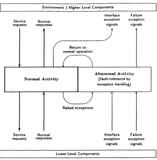
E n v ironm ent / H igher Level C o m p o n e n ts
Service
re q u e sts resp o n sesN orm al
In terface Failure e x cep tio n exception
signals signals
R e tu rn to norm al o p e ra tio n
A b n o r m a l A c t i v it y (fa u lt-to le ra n c e by e x cep tio n h an d lin g ) N o r m a l A c t i v it y
Raised e x c e p tio n s
Service re q u e sts
N orm al resp o n ses
In te rfa c e Failure e x cep tio n ex cep tio n
signals signals Low er Level C o m p o n e n ts
Figure 2.2: Framework for an Ideal Exception-based Fault-tolerant C om ponent
An alternative form of recovering from foreseeable errors is to write the algorithm as
if no error of this kind would ever occur and, then, provide a test mechanism at lower
levels. Should an error be detected, an exception is raised and th e error is tre a ted
by a separate module, exclusively designed to deal with this exceptional situation.
This technique is known as exception handling [AL81, Cri82, CR8 6, PW 90, Iss92].
Exceptions can be raised by the apphcation module, th e operating system , or by
hardw are components. Figure 2.2 depicts an ideal component based on exception
handhng. The left side of the figure illustrates th e norm al behaviour of the com
ponent: it receives requests from the upper level, deals w ith them , and sends th e
answers back to the upper level. If the com ponent rehes on lower level modules to
execute at least p art of the request, it re-sends the request, or part of it, to th e lower
Chapter 2. Review on Software Fault-Tolerance 38
W hen a request is received from th e upper level, it is verified and, if it is not a
vahd input, an interface exception is signalled back to the upper level. Similarly,
th e component will receive an interface signal from the lower level, if it has passed
an incorrect set of param eters to it.
If an error is detected during the norm al com putation, an exception is raised
and the execution how is transferred to th e right side of th e hgure. The exception
handler tries to recover from the error. If it succeeds, th e norm al execution how
is resumed. If it fails, the module reports the failure to th e upper level by sending
a failure exception signal. An analogous procedure is followed when unrecovered
errors are reported by th e lower level.
2 .4 .3
R e c o v e r y B lo c k s
Recovery blocks [Ran75] allow structuring of diversely designed versions of a module
in order to achieve fault-tolerance. These versions, called alternatives, are invoked
one by one, according to th e order in which they have been enum erated in th e
specihcation of the recovery block. T he o u tp u ts of each of th e alternatives are
validated by an acceptance test before being retu rn ed to th e calling module. If they
fail the test, the module rolls back to the beginning of the recovery block, hence
undoing aU modihcations in th e variables made by th e alternative. It th en executes
th e next alternative. If none of the alternatives is able to produce an acceptable
result, an error is signalled to the procedure th a t called th e recovery block. Recovery
blocks can be used to provide both forward and backw ard error recovery.
Figure 2.3 shows a recovery block w ith two alternatives^. In this exam ple, if th e
o u tp u ts of alternative A P fail th e acceptance test A T , alternative A Q will be used
instead. If it does not produce an acceptable result, th e recovery block A will re tu rn
Chapter 2. Review on Software Fault-Tolerance 39
A : e n s u r e A T b y A P : b e g in program text e n d e ls e b y A Q : b e g in
program text e n d e ls e e r r o r
Figure 2.3: Example of a Recovery Block
an error indication. Recovery blocks can be nested, i.e., the alternatives can contain
recovery blocks.
The prim ary alternative wiU always be th e first one to be invoked by th e recovery
block. Therefore, it ought to be the one which provides th e most suitable result.
T he others, if necessary, m ay lead to less accurate, although acceptable, results. If
all alternatives produce equally acceptable results, th e cheapest to com pute m ust
be th e prim ary alternative.
Assuming th a t faults will manifest themselves only in a very lim ited set of inputs,
m ost of th e tim e th e alternatives will produce correct results. Hence, when an
alternative fails, it is not excluded from the recovery block, because in the long
ru n it m ay be less costly to roll th e m odule back and execute another alternative
occasionally th a n to use a less efficient alternative every tim e th e recovery block is
called.
A cceptance tests do not guarantee th e correctness of o utp u ts th a t they have
validated. They merely state th a t th e o u tp u ts are in accordance w ith pre-estabHshed
criteria, such as belonging to a particular set of values, or having th eir elements
arranged in a specific order. Thus, erroneous outputs m ay sometimes be accepted
as vahd due to the hm itations of the assessment criterion. However, correct results
will never be rejected, unless th e acceptance test is faulty. T he acceptance test m ust
be as simple as possible in order to avoid design faults. W hen recovery blocks are
nested, incidental errors caused by faults in acceptance tests m ay be recovered in
Chapter 2. Review on Software Fault-Tolerance 40
oracle, because if it were capable of foreseeing the correct o u tp u t for every possible
in p u t, there would be no need for the recovery block in the first place.
An alternative may change the contents of global variables. However, if its
o u tp u t is rejected by the acceptance test, the original value of these variables ought
to be restored during the rollback procedure. This can be achieved by means of
an algorithm similar to a database transaction called recursive cache. A recursive
cache mechanism can be implemented by creating a tem porary buffer where the
new values of the global variables are held whilst th e alternative is active [Ran75].
W henever a global variable is read, it is done either from its perm anent address,
if it has not been changed by the alternative or, otherwise, from the buffer. The
values stored in the tem porary buffer are made perm anent only if the alternative is
successful, else they are discarded.
In real-tim e apphcations, the sequential execution of th e alternatives m ay be
inadmissible, due to the tim e taken to roll back th e apphcation to th e beginning
of th e recovery block and to execute th e next alternative in hne. In order for this
approach to be suitable for real-time systems, the recovery block m ust be able to
comply w ith the tim e constraints of the apphcation in th e worst-case scenario, i.e.,
when all of the alternatives need to be invoked.
D uring its execution, the alternative m ay need to com m unicate w ith other com
ponents of the system. Since this interaction occurs before th e o u tp u t of the alter
n ative is assessed by the acceptance test, it is possible th a t it contam inates other
com ponents by exporting erroneous values to them . The contam ination can spread
even fu rth er if the recipient exports messages to other processes. C ontam ination
can also occur in the opposite direction. The alternative m ay utihse values im
p o rted from other components. Should these values be incorrect, it is hkely th a t
th e o u tp u ts of the alternative wiU be rejected by th e acceptance test. Moreover,
if oth er alternatives obtain these values from the same source, none of them will
en-Chapter 2. Review on Software Fault-Tolerance 41
sure error confinement [LK8 6], i.e., th a t erroneous d a ta is not tran sm itted to other
com ponents.
2 .4 .4
C o n v e r sa tio n s
D epending on how modules in a fault-tolerant concurrent system based on backw ard
error recovery interact with one another, an error detection in one of them m ay cause
many, or even all the modules to roll back to further behind their last checkpoints,
including those which have not interacted directly w ith th e faulty module. This
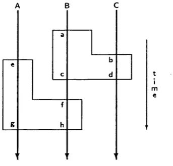
bizarre behaviour is known as the domino effect [RLT78]. Figure 2.4 depicts a
configuration where th e domino effect occurs. Processes A, B, and C are somewhere
ahead of th eir fourth recoverable checkpoint^. If an error is detected in process C ,.
it wiU roll back to checkpoint num ber 4. However, as it has com m unicated w ith
process B after checkpoint 4, B m ay have been contam inated. Hence, B m ust roll
back to th e closest checkpoint before its interaction w ith C, which is checkpoint
num ber 3. B may have contam inated A, because they have com m unicated after B
has exchanged possibly wrong messages with C. Therefore, A m ust roll back to its
checkpoint num ber 3. Continuing w ith this analysis, it can be seen th a t all processes
will eventually roU back to checkpoints num ber 1.
T h e domino effect can happen when the interaction of fault-tolerant com ponents
in concurrent systems is not co-ordinated properly. Conversations [Ran75] is a tech
nique for structuring communicating processes in order to contain contam ination.
Conversations estabhsh well-defined boundaries within which com m unicating com
ponents are allowed to interact. Communication outside conversations is forbidden.
T he com ponents th a t participate in a conversation are checkpointed when they en
te r th e conversation. If an error is detected in any of the com ponents, all m em bers
Chapter 2. Review on Software Fault-Tolerance 42
A:
B: 1
C:
L e g e n d : # = ch eck p o in t
I = in te rp ro c e ss c o m m u n ic a tio n
Figure 2.4: The Domino Effect
of the conversation roll back to the beginning of th e conversation. Com ponents
th a t are not m em bers of the same conversation cannot contam inate one another,
because they do not interact. This ensures th a t members of a conversation do not
need to roll back to checkpoints located before the beginning of th e conversation.
The domino effect is thus hm ited to the beginning of the conversation. W hen th e
members leave th e conversation, they are assessed and checkpointed again in order
to prevent them from rolling back into the conversation due an error which occurs
after they have left th e conversation. If a member is found to be in error after it
has left the conversation, none of the other members are affected.
Components can join a conversation at different times, provided th a t they do
not com m unicate before having done so. However, they m ust leave th e conversation
at the same tim e in order to ensure th a t none of th e m em bers are required to roll
back into the conversation after having left it. If this rule is not enforced and an
error is detected when one of the members is leaving the conversation, m em bers
which have already left th e conversation will need to roU back to th e beginning of
the conversation. However, rolling these components back to th e beginning of th e
original conversation would affect th e members of conversations th a t they m ight
have joined after they have left the original one.
Chapter 2. Review on Software Fault-Tolerance 43
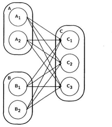
Figure 2.5: Processes Transactions via Conversations
1. Processes m ust join the conversation before th ey in teract.
2. All processes m ust leave th e conversation at th e same tim e.
Figure 2.5 illustrates two conversations: one betw een modules A and B, and
another between com ponents B and C. Modules B and C jo in th e conversation at
different m om ents (a and b), b u t communication betw een th em commences only
after C has reached point b (rule 1). In order to comply w ith rule 2, they leave
the conversation at th e same tim e (c and d). The sam e appUes to th e conversation
betw een modules A and B. Module A is allowed to join its conversation w ith com
ponent B at point e, before the conversation between B and C term inates. However,
communication betw een A and B commences only after B has reached point f.
As a backward error recovery technique, conversations suffer from th e same real
tim e hm itations th a t are present in th e canonical im plem entation of recovery blocks.
A nother drawback of this software fault-tolerance technique is to roll back all th e
mem bers of a conversation when an error is detected in one of th em , since, theo reti
cally, only the faulty m em ber and those which have been contam inated ought to roll
back. The impossibility of determ ining where the fault th a t caused th e error is lo
Chapter 2. Review on Software F a u l t -Tolerance 44
M o d u le 1
M o d u le 3 M o d u le 2
V o te rs
Figure 2.6: General Triple-M odular Reduncancy (T M R ) Diagram
contam ination does occur w ithin th e conversation.
2 .4 .5
N -V e r s io n P r o g r a m m in g
N-version programming [Avi85] is another software fault-tolerance technique based
on design diversity. In this approach, n diversely designed versions of th e same
module are executed concurrently and their individual o u tp u ts are com pared in
order to decide upon a single result. If no consensus is reached, an error is indicated.
N-version program m ing is th e software counterpart of th e hardw are technique
Triple Modular Redundancy (T M R ) [RLT78]. Figure 2 . 6 depicts a T M R fault-
toleran t hardw are architecture where three parallel channels are utilised. Modules
1, 2, and 3 are diversely designed components which comply w ith th e same speci
fication. Each of th e versions receives the same set of inputs and provides its own
outp u ts. In order to ensure th a t th e three channels wiU contain the same inform a
tion after th e three modules have issued their outputs, each channel has a voter at
which th e outputs of the three versions are compared to one another in order to
produce a rehable result.