2606
Walking Stability Control System on Humanoid
When Turning Based on LQR Method
Andi Dharmawan, Curie Habiba, Muhammad AuzanAbstract: When a humanoid robot turns, the centre of mass of the robot moves with its body. This rotation causes an unwanted moment on the sole and causes the robot to become unbalanced. If the projection of the centre of mass on the foot of the humanoid robot moves beyond the supporting leg's limit, then that moment can cause the robot to fall. Therefore, we need a control system to optimize the movement of the centre of mass in a humanoid robot. In this study, we use the Linear Quadratic Regulator (LQR) method to handle this. The inverted-pendulum mathematical model is used as a control system response approach to the robot. The position of the centre of mass of the robot is obtained by reading the position of 12 servos on foot and using forward-kinematics. The current position of the centre of mass of the robot is corrected by the desired centre of mass resulting from the walking pattern. The results of these corrections serve as input controls to stabilize the robot. The result of the control is the torque which must be produced by the robot actuator. The torque is converted to the angle and angular velocity of the pitch and roll on the robot's ankle. Inverse kinematics is used to calculate the angle of each foot servo and make the walking motion according to the walking pattern (both straight and turning). The results showed humanoid robots when turning can reduce overshoot in the system and speed up the system response time compared to the system response without LQR control.
Index Terms: control, forward-kinematics, inverted-pendulum, LQR, robot, turning, walking-pattern. —————————— ——————————
1.
INTRODUCTION
robot has several types, including wheeled robots, legged robots, and spherical rolling. One type of legged robot is a humanoid robot that has a shape resembling a human. A humanoid robot has several advantages that other types of robots do not have. One of them is a humanoid robot that can work in complex human environments and uneven terrain [1]. This ability is supported by humanoid robot form that resembles humans, thus making it able to adapt to the environment. Therefore, a humanoid robot is more appropriate to help humans with daily tasks in the human environment [2]. Walking is a fundamental ability that must be possessed by a humanoid robot in order to be able to do work in the human environment [3]. Humanoid robots must be able to walk in all directions or can be called omnidirectional walking. Omnidirectional walking on the humanoid is done by walking in all directions without changing the direction facing its whole body. Omnidirectional walking can also be done by turning by changing the direction facing its body. When the stationary position with the legs parallel, the humanoid robot is in a balanced state. However, when it starts to move, the centre of mass or Centre of Mass (CoM) humanoid robot moves. This condition can cause a humanoid robot to tend to fall. When the robot turns, CoM displacement follows the rotation of the robot body, causing a moment on the sole of the robot's foot which causes the robot to become unbalanced [4]. If the CoM projection of the foot of the humanoid robot moves beyond the supporting leg's limit, then a moment will occur, which can cause the robot to fall. This concept of stability is known as the Zero Moment Point (ZMP) stability concept [5]. Therefore, when turning, a humanoid robot requires actions to prevent the robot from falling, such as supporting leg movements and adequate torso to keep the CoM within the supporting leg boundary and placing the supporting leg next at the right time
and place [6]. Proper footwork planning and walking concepts are needed to maintain the stability of the humanoid robot. The concept of walking has been used and can maintain the stability of humanoid robots when walking, one of which is the inverted pendulum [7]. This inverted pendulum concept involves a CoM that moves when a humanoid robot moves. When turning, a humanoid robot is expected to be able to maintain CoM height by stepping as fast as possible before the robot falls. This method can be approached with the concept of Linear Inverted Pendulum (LIPM) [8]. In addition to the concept of walking, control on humanoid robots is also needed as a stabilizer. PID (Proportional Integral Derivative) method has been applied to previous studies to control each servo when running [9]. However, this control still causes overshoot of more than 30% and the response time is quite long (more than one second). This condition is caused by PID that can only handle Single Input and produce Single Output (SISO) so that it provides feedback one by one [10] [11]. So, if it is applied to a robot when it turns, it has a greater tendency to fall. Therefore, a more suitable control system is needed to be applied to humanoid robots when turning.
A humanoid robot uses a Multiple Input Multiple Output (MIMO) system where the joint torques are input and output vectors [12]. Linear Quadratic Regulator (LQR) is a control that can be implemented on MIMO systems [13]. The walking pattern that has been made with the concept of an inverted pendulum and supported by LQR control as a stabilizer will make the humanoid robot be able to walk with minimal errors.
2
RESEARCH
METHODS
2.1 System Description
This study only involved the body and legs so that it focused on controlling the motion of the foot when turning. The parts of the robot that were the focus of this study consisted of the body, hips, thighs, knees, calves, ankles, and soles. The robot uses 12 servos to move two legs. The humanoid robot model is represented as a two-dimensional inverted pendulum [14]. The system model is shown in Fig. 1.
A
————————————————
Andi Dharmawan is a lecturer in electronics and instrumentation undergraduate program, Universitas Gadjah Mada, Indonesia, E-mail: [email protected]
Curie Habiba is currently pursuing master’s degree program in
computer science in Universitas Gadjah Mada, Indonesia
Muhammad Auzan is currently pursuing master’s degree program in
2607
Fig. 1 Model of an inverted pendulum
The inverted pendulum model with the Newton-Euler approach, as in Fig. 1, is shown equation (1),
𝐼𝜃̈ − 𝑚𝑔𝑙 sin 𝜃 = 𝜏 (1)
where 𝑚 is the pendulum mass, 𝑙 is the length of the pendulum arm, 𝜃 is the deviation of the pendulum angle, 𝐼 is the pendulum inertia moment, and 𝜏 is the pendulum torque. Humanoid state robots are obtained using the Denavit Hatenberg (DH) forward kinematics [15]. There is a local coordinate rule in the DH forward kinematics. The rule is the coordinate axis leading to the direction of rotation of the joint is the 𝑧-coordinate axis, while the 𝑥 and 𝑦 coordinates are perpendicular to each other following the right-hand rule. Humanoid configuration using DH kinematics forward is shown in Fig. 2. The humanoid configuration is then used to determine the local coordinates of the humanoid following the DH rules.
Fig. 2 Humanoid configuration using DH kinematics forward
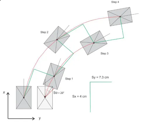
Static walking patterns are used to achieve robot stability. The inverted pendulum model is applied in making robot walking patterns. In this model, it is assumed that the total mass of the robot is in the Centre of Mass (CoM) point. Equilibrium in the static walking pattern is obtained when CoM never comes out of the area of stability, namely the convex hull from all points of contact between the foot and the floor [16] The robot makes a turn following the leg-first walking model [17]. The pattern of walking starts from the state of the robot standing by bending the knee. The goal is when stepping foot robot can extend to maintain its height. Then the robot will tilt its body, causing the displacement of the CoM to get ready
to move. After CoM has moved, the non-supporting leg swings forward or sideways in the direction it turns [18]. The turning pattern is shown in
Fig. 3.
Fig. 3 Turning pattern
2.2 Electronics Design
The humanoid robot electronic system architecture is designed by being equipped with servos which have position sensors and microcontrollers as in
Fig. 4. Each of the servos is the Dynamixel AX-12A series which can produce a torque of 15.3 kg.cm and read angles and move with the smallest tolerance of 0.29 degrees. The microcontroller used is OpenCM, which has a module to communicate with all of the Dynamixel AX-12A servos.
Fig. 4 Electronic system architecture
Electronic and battery laying is in the middle of the body. So, the CoM of the robot remains between the right and left legs. The robot has a length of 10.6 cm, a width of 13.7 cm and a height of 34.2 cm with a plastic frame. The robot has a total weight of 1.126 kg consisting of electronics, servo and frames.
2.3 Control System Design
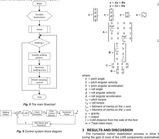
2608 Fig. 5 shows the main flowchart of it. The flowchart consists of
variable declarations, set up functions, robot stepping control functions, etc. The robot will read the angular value obtained from the sensor on the servo in real time to find out the error. This research uses the Linear Quadratic Regulator (LQR) control method. LQR is the development of the Hamilton-Jacobi-Bellman (HJB) method [19]. The main objective of LQR control is to optimize the full state feedback system by minimizing the cost function. The control block diagram of the humanoid robot walking balance system when turning is shown in
Fig. 6. The walking pattern of the
Fig. 6 is described in Fig. 7. The flight walking process aims to generate the roll and pitch angles that must be formed by the humanoid robot in order to stabilize its walking. But the process is also still paying attention not to let the humanoid robot moves outside the predetermined pattern.
Begin
Variable declarations
Setup
Walking ?
Update walking pattern.
Generate walking track
Robot stepping control
End
Fig. 5 The main flowchart
Fig. 6 Control system block diagram
Fig. 7 Walking Pattern Block Diagram
This humanoid robot uses MIMO system to stabilize its attitude, where the controlled parameters consist of four states consisting of pitch angle, pitch angular velocity, roll angle, and roll angular velocity. This situation requires the robot model to be represented in the state space based on the general equation of the inverted pendulum. Therefore, equations (2) [20] and (3) are obtained.
̇ = (2)
=
̇ =
[ 𝜃̇
𝜃̈ ̇ ̈]
= [
𝜃 𝜃̇
̇]
= [ ] 𝜃 = [𝜏𝜏 ]
(3)
=
[ 𝑚𝑔𝑙
𝐼
𝑚𝑔𝑙 𝐼 ]
=
[ 𝐼
𝐼 ]
= [ ]
= [ ]
where:
𝜃 = pitch angle
𝜃̇ = pitch angular velocity
𝜃̈ = pitch angular acceleration
= roll angle
̇ = roll angular velocity
̈ = roll angular acceleration
𝜏 = pitch torque
𝜏 = roll torque
𝐼 = Moment of inertia on the 𝑥-axis
𝐼 = Moment of inertia on the 𝑦-axis
𝑔 = gravity
= output
𝑙 = CoM distance from the sole of the foot
𝑚 = Total robot mass
3 RESULTS
AND
DISCUSSION
The humanoid motion stabilization process is done by tuning the gain Q (one of the LQR components) automatically through a simulation. The results obtained when the simulation is then validated on robots in the real world by adjusting the system response. This method is done to obtain the optimal
CoM body coordinates on the global
frame of the turning pattern
Inverse Kinematic
𝜙𝑟𝑒𝑓
𝜙̇𝑟𝑒𝑓
𝜃𝑟𝑒𝑓
2609 system response. Furthermore, the turn-taking test is carried
out at a turning angle variation of 5 °, 10 °, 15 °, and 20 ° by following the walking pattern in
Fig. 3.
3.1 Right Turning Humanoid Testing
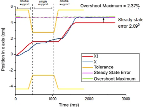
The system responses shown in Fig. 8 and Fig. 9 are the response in step 4 of the test with a turning angle of 20°. The fourth step is the last step of the robot before the robot stops moving. The gain from the simulation results used in the straight-walk test has differences in terms of its response to the applied in the turning test. An additional disturbance causes this situation in the form of momentum generated by turning motion. Therefore, the tuning of 𝐐 value is done again to get the best response results for right turn testing. The value of the full state feedback gain 𝐊 as the output of the LQR method on the control affects the amount of torque released by the servo. The higher the torque, the faster the system response. Too little torque causes system delay, especially when the robot is in a single support state, so it does not fall inward. Single support is a condition where the load of the robot is only piled on one foot, and with a tolerance of the position of the centre of mass which is rather narrow, the width is only as big as one foot. If the torque is too large, it can result in a system response that is too fast and higher overshoot, which can cause the system to oscillate and the robot falls outwards. The system response on the 𝑥-axis shows the centre of mass can follow the turning pattern with a maximum overshoot of 2.37% and a steady-state error of 2.09° where the robot can still handle the condition. The response of the system on the 𝑦-axis shows better results than the 𝑥-axis, where the centre of mass can follow the pattern of turning without overshoot and steady-state error of only 0.36°. Variables and results of robotic control experiments when right turn is summarized in
TABLE 1. The results of the experiment on the variation of the right turn angle showed that the robot was able to follow the walking pattern. The results show that there is a maximum overshoot of 2.22% for the pitch response on the 𝑥-axis, and 3.3% for the roll response on the 𝑦-axis. Furthermore, there are a steady-state error of 2.04 ° for the pitch response and 0.18 ° for the response roll.
Fig. 8 The test results of right turn by 20° concerning the 𝑥 -axis.
Fig. 9 The test results of right turn by 20° concerning the 𝑦 -axis
TABLE 1
VARIABLES AND RESULTS OF ROBOTIC CONTROL EXPERIMENTS WHEN TURNING RIGHT
𝐐 =
̇= = ̇=
𝐊 =
̇ =
=
̇ =
Step Length 4 cm Step Period 1.5 s
Turning Angle
Steady state error (degree) Overshoot maximum
𝜃 𝑥 𝑦
5° 1.96° 0.13° 4.35% 673%
10° 2.00° 0.13° 1.52% 0.73%
15° 2.10° 0.13° 0.65% 0 %
20° 2.10° 0.36° 2.37% 0 %
3.2 Left Turning Humanoid Testing
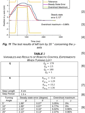
The system response shown in Fig. 10 and Fig. 11 is the response in step 4 of the 20° left turn test. The full-state feedback gain 𝐊 values used in the right turn test runs have different system response results when applied to the left turn test. Therefore, validation is performed at 𝐐 gain so that the optimal response results for left turn testing are obtained. The system response on the 𝑥-axis shows the centre of mass can follow the turning pattern with a maximum overshoot of 2.37% and a steady-state error of 2.13°. System response on the 𝑦 -axis shows better results than the 𝑥-axis, where the centre of mass can follow the pattern of turning with a maximum overshoot of 0.96% and a steady-state error of 0.13 °. Variables and research results of humanoid robot control when left turn are summarized in
2610
Fig. 10 The test results of left turn by 20 ° concerning the 𝑥 -axis
Fig. 11 The test results of left turn by 20 ° concerning the 𝑦 -axis
TABLE 2
VARIABLES AND RESULTS OF ROBOTIC CONTROL EXPERIMENTS WHEN TURNING LEFT
𝐐 =
̇= = ̇=
𝐊 =
̇ =
=
̇ =
Step Length 4 cm Step Period 1.5 s
Turning Angle
Steady state error (degree) Overshoot maximum
𝜃 𝑥 𝑦
5° 1.89° 0.07° 3.05% 0%
10° 1.89° 0.07° 6.77% 0%
15° 2.13° 0.10° 6.02% 0.96%
20° 2.13° 0.13° 2.37% 0.96%
Testing the variation of the left turn angle is carried out using the same full state feedback gain 𝐊 values and the walking pattern. The experimental results of left turn angle variation showed that a humanoid robot was able to follow the walking pattern with a
maximum overshoot of 4.55% for pitch response on the 𝑥-axis and 0.48% for roll response on the 𝑦-axis. There is also a steady-state error of 2.01° for pitch response and 0.09° for roll response.
4 CONCLUSIONS
Based on the research that has been done, it is obtained that the LQR-based control system can make the robot turn up to 80 ° in four steps without falling. The walking pattern is implemented using the leg-first walking model. Humanoid robots can maintain the stability of humanoid robots when turning with optimal system response. This situation causes the robot does not fall when turning.
ACKNOWLEDGMENT
This work was supported by Faculty of Mathematics and Natural Sciences, Universitas Gadjah Mada for the research grant.
REFERENCES
[1] S. Kajita et al., ―Biped walking pattern generation by using preview control of zero-moment point,‖ in 2003 IEEE International Conference on Robotics and Automation (Cat. No.03CH37422), 2003, pp. 1620– 1626.
[2] X. Tao and C. Qijun, ―A Simple Rebalance Strategy for Omnidirectional Humanoids Walking by Learning Foot Positioning,‖ in Control Conference (ASCC), 2011 8th Asian, 2011, pp. 1340–1345.
[3] M. Akhtaruzzaman and A. A. Shafie, ―Geometrical analysis on BIOLOID humanoid system standing on single leg,‖ in 2011 4th International Conference on Mechatronics (ICOM), 2011, no. May, pp. 1–5.
[4] S. Dalibard, A. El Khoury, F. Lamiraux, A. Nakhaei, M. Taïx, and J.-P. Laumond, ―Dynamic walking and whole-body motion planning for humanoid robots: an integrated approach,‖ Int. J. Rob. Res., vol. 32, no. 9– 10, pp. 1089–1103, Aug. 2013.
[5] J. J. Alcaraz-Jiménez, D. Herrero-Pérez, and H. Martínez-Barberá, ―Robust feedback control of ZMP-based gait for the humanoid robot Nao,‖ Int. J. Rob. Res., vol. 32, no. 9–10, pp. 1074–1088, Aug. 2013. [6] Y.-L. Hwang, T.-N. Ta, C.-H. Chen, and K.-N. Chen,
―Using Zero Moment Point preview control formulation to generate nonlinear trajectories of walking patterns on humanoid robots,‖ in 2015 12th International Conference on Fuzzy Systems and Knowledge Discovery (FSKD), 2015, no. Fskd, pp. 2405–2411. [7] J.-C. Lu, J.-Y. Chen, and P.-C. Lin, ―Turning in a
Bipedal Robot,‖ J. Bionic Eng., vol. 10, no. 3, pp. 292– 304, Sep. 2013.
[8] R. Bimarta, A. E. Putra, and A. Dharmawan, ―Balancing Robot Menggunakan Metode Kendali Proporsional Integral Derivatif,‖ IJEIS (Indonesian J. Electron. Instrum. Syst., vol. 5, no. 1, p. 89, May 2015.
[9] M. Missura and S. Behnke, ―Omnidirectional capture steps for bipedal walking,‖ in 2013 13th IEEE-RAS International Conference on Humanoid Robots (Humanoids), 2013, vol. 2015-Febru, no. February, pp. 14–20.
2611 UAV system,‖ in AIP Conf. Proc. 1755, 170011 (2016),
2016, vol. 1755, p. 170011.
[11] D. Lelono, K. Triyana, S. Hartati, and J. E. Istiyanto, ―Development of Electronic Nose with High Stable Sample Heater to Classify Quality Levels of Local Black Tea,‖ Int. J. Adv. Sci. Eng. Inf. Technol., vol. 7, no. 2, p. 352, Apr. 2017.
[12] R. Gautam and A. T. Patil, ―Modeling and control of joint angles of a biped robot leg using PID controllers,‖ in 2015 IEEE International Conference on Engineering and Technology (ICETECH), 2015, pp. 1–5.
[13] O. A. Dhewa, A. Dharmawan, and T. K. Priyambodo, ―Model of Linear Quadratic Regulator (LQR) Control Method in Hovering State of Quadrotor,‖ J. Telecommun. Electron. Comput. Eng., vol. 9, no. 3, pp. 135–143, 2017.
[14] S. Kajita, H. Hirukawa, K. Harada, and K. Yokoi, Introduction to Humanoid Robotics, vol. 101. Berlin, Heidelberg: Springer Berlin Heidelberg, 2014.
[15] S. Kucuk and Z. Bingul, Robot Kinematics - Forward and Inverse Kinematics. Germany: Pro Literatur Verlag, Germany / ARS, Austria, 2007.
[16] S. Mason, N. Rotella, S. Schaal, and L. Righetti, ―Balancing and walking using full dynamics LQR control with contact constraints,‖ in 2016 IEEE-RAS 16th International Conference on Humanoid Robots (Humanoids), 2016, vol. 2015-Decem, pp. 63–68. [17] Fei Wang, Yaning Wang, Shiguang Wen, and Shuying
Zhao, ―Nao humanoid robot gait planning based on the linear inverted pendulum,‖ in 2012 24th Chinese Control and Decision Conference (CCDC), 2012, pp. 986–990.
[18] S. Behnke, ―Online trajectory generation for omnidirectional biped walking,‖ in Proceedings 2006 IEEE International Conference on Robotics and Automation, 2006. ICRA 2006., 2006, vol. 2006, no. May, pp. 1597–1603.
[19] E. Lavretsky and K. A. Wise, Robust and Adaptive Control. London: Springer London, 2013.