114
A Sensing Platform For A UHF RFID System
Young Ho Lee, Ivan Marsic
Abstract: As the read range of passive UHF RFID broadens up to 11 meters compared to 1-meter range of HF RFID, passive tags have been used for many applications such as tracking medical devices and objects of daily living. The RF communication link between the reader antenna and tags for indoors exhibits intermittent loss of signal reception due to antenna orientation mismatch and breakpoints within the antenna coverage area. We propose a design of a sensing platform for tracking objects using a UHF RFID system with passive tags that provides continuous signal reception over the coverage area. We first investigated causes of power loss for passive tags and then designed a sensing platform solution using antenna diversity. The causes of tag’s power loss were eliminated with angle and spatial diversity methods that can cover an arbitrary area of interest. We implemented this design in an indoor setting of a trauma resuscitation room and evaluated it by experimental measurement of signal strength at different points and angles in the area of interest. Our sensing platform supported complete coverage and uninterrupted interrogation of tags as they moved in the area of interest. We conclude that this sensing platform will be suitable for uninterrupted object tracking with UHF RFID technology in generic indoor spaces.
Index Terms: UHF RFID system, sensing platform, uninterrupted interrogation..
————————————————————
1 Introduction
RADIO-frequency identification (RFID) technology has been used in a variety of areas for its primary function of identifying objects. Additionally, a new research area of object tracking has emerged based on a secondary function of providing received signal strength indication (RSSI) and received signal phase. In this area studies attached ultra-high frequency (UHF) RFID passive tags on objects to track objects and recognize activities [1][2][3][4]. Because passive RFID tags harvest energy from the interrogation signal of readers to activate, discontinuities in the reader signal within the working range will cause power loss of the tags. In the object tracking application, it is critical that passive tags receive activation power continuously from the reader signal. If readers cannot provide passive tags with proper power, the tags will not activate and respond to reader’s interrogation, making the direct tracking difficult. As the working range of UHF RFID is expanded up to 11 meters [5] compared to 1 meter of high frequency (HF) RFID, UHF signals have suffered more for signal discontinuities within the coverage. Several studies have indicated power loss of the passive UHF RFID tags [1][6][7][8]. Our study focused on the design of a sensing platform for a UHF RFID system to provide continuous signal reception for tracking objects based on RSSI which is the received signal strength information on backscatter from a passive tag at the reader. RSSI represents the measurement of the relative signal power between the reader antenna and the tag at a given location. We investigated the causes of power loss for passive tags and provided a sensing platform solution using angle and spatial diversity of antennas. We applied this platform to a crowded indoor setting of a trauma resuscitation room. The fast-paced, high-risk hospital environments such as trauma resuscitation and surgical operation can benefit from context-aware systems that recognize and analyze currently performed activities.
Other studies have used passive RFID tags for tracking medical objects as part of a context-aware system, but provided no specific sensing platforms to deal with power loss of passive tags [2][3][9][10]. In this paper, we present a platform based on a UHF RFID system to provide sensing free of power loss for UHF passive tags. This paper focuses on power loss of tags in indoor environments caused natural phenomena. Other sources of power loss, such as people moving around while doing their work and causing occlusions and reflections that introduce interference to RSSI measurements, will be addressed in our future work. Our key design aim was to provide uninterrupted reader signal over the area of interest with a nonintrusive system. The reader antennas or other related devices should not be in the paths of people’s work and equipment movement. The long range of UHF tags (11 meters) allows us to install RFID reader antennas on the room ceiling, since the height of the ceiling is typically no more than 4 meters. To provide uninterrupted reader signal, we investigated the main challenges causing the power loss: human occlusion, indoor multipath fading, and antenna orientation mismatch between the reader antennas and tags. First, because the radio signals of an RFID system cannot penetrate human body, tags occluded by people are rarely activated. To secure different paths of the reader signal, we employed multiple reader antennas located at the room ceiling. The number and exact locations of those antennas are calculated by accounting for the orientation mismatch and the breakpoints. Second, the orientation mismatch causes power loss, leaving passive tags inactivated and unable to provide information to the reader. Because the tag antenna is directional, there is power attenuation due to the orientation mismatch between the reader and the tag. Complete orientation mismatch will result in zero power delivered to the tag. We introduced angle diversity to prevent the power loss from the orientation mismatch. Third, the breakpoints also account for power loss of passive tags. Indoor radio signals undergo scattering, multipath, and delay spread, and the effects of these propagations include constructive and destructive interference [7][11][12]. While the constructive interference strengthens the radio signal, the destructive interference often makes deep fades, called ―breakpoints,‖ in which tags become undetectable even within the working range [12][13][14]. To cover this effect, we investigated breakpoints and introduced antenna diversity by arranging reader antennas at different angles over the area of interest. To address the above challenges and develop a sensing platform, we first modeled the workspace in our laboratory, __________________________
Young Ho Lee is currently pursuing PhD degree program in Electrical and Computer Engineering at Rutgers University, USA, e-mail:
Ivan Marsic is a professor of Electrical and Computer Engineering at Rutgers University, USA, e-mail:
115 because the actual workspace cannot be used for
time-consuming system development. We used commercial off-the-shelf (COTS) technology which includes an RFID reader, reader antennas and passive UHF tags. This paper makes three contributions. First, using simulation and experimental measurements we characterized power loss problems and demonstrated that a single antenna cannot continuously track tags within its own range due to breakpoints and orientation-mismatch problems. Second, we presented a sensing platform design of a UHF RFID system with angle and spatial diversity as a solution to the power loss problems and applied it to a crowded indoor space. We then empirically verified the sensing platform by measuring RSSI at different locations and angles within the area of interest. Third, we successfully addressed power loss problems with continuous RFID data acquisition, eliminating power loss over the area of interest. This sensing platform with small modifications will be suitable for uninterrupted object tracking with UHF RFID technology in generic crowded indoor spaces. The rest of this paper is organized as follows. In Section 2, the related work on indoor propagation of the UHF RFID bands and reader antenna deployments is reviewed. In Section 3, the power loss problems of human occlusion, antenna orientation mismatch and breakpoints are investigated. The detailed design requirements and solutions are then presented for a indoor space. In Section 4, we verify the proposed sensing platform by measuring breakpoints and RSSI values at different angles in the area of interest. We conclude in Section 5.
2 Related Work
A study of wave propagation and backscatter communication link in an office environment using a network analyzer showed deep fades (―breakpoints‖) even within a line-of-sight [8]. They demonstrated that a simple statistical channel model in general does not hold for indoor propagation. Another study evaluated the minimum activation power of the tag (10 dBm) using a small anechoic chamber and showed that the signal strength of each UHF RFID channel (50 channels in the range 902.75 – 927.25 MHz) met the 10 dBm turn-on threshold [6]. Based on their results, we localized the breakpoints by measuring the RSSI values in the area of interest and checking if the tag was below the turn-on threshold and did not respond to interrogation. We used these breakpoint locations as a design parameter of our sensing platform. Tag’s signal power attenuation from orientation mismatch between the tag and reader antenna have been examined [5][20]. These studies, however, provided no design solutions for tag’s power loss. Our three-dimensional visualization of their model showed that at certain angles a far-below-the-activation power of the tag causes complete power loss, which we also verified experimentally. As a result, in an indoor environment there are breakpoints and orientation mismatches within a line-of-sight that cause tag’s power loss in the coverage of a reader antenna. Previous studies using passive RSSI ranging applied a single reader antenna to cover tags in the antenna range [15][16][17][18]. A single antenna is, however, inadequate to sense tags at all distances from the antenna due to the orientation mismatch and breakpoints, and it is not able to provide continuous tag reading even for tags within its coverage area. On the other hand, studies that used multiple antennas analyzed the dependence of application performance accuracy on different configurations of redundant antennas to determine the proper positions and number of
antennas to cover the area of interest [2][3]. However, they did not analyze power loss of a tag nor designed a sensing platform systematically using the antenna specification. We also used multiple antennas for the area of interest. We, however, investigated radio specification of an RFID antenna and the causes of power loss of passive tags, and provided a sensing platform.
3 The Sensing Platform Configuration
Our sensing platform is designed to provide uninterrupted interrogation signals to passive UHF tags attached on tracked objects as they are moved around the area of interest. The communication protocol of the UHF RFID system, EPC Class-1 Generation-2 standard, supports a multi-access method for the interrogation of multiple tags using a variation of the slotted Aloha protocol [27]. Each individual tag, however, must receive sufficient interrogation signal power in order to activate and respond. The main impediments to reading passive UHF RFID tags uninterruptedly include human occlusion, orientation mismatch, and breakpoints. This section describes those impediments and key design aspects of the sensing platform.
A. Human Occlusion
A key impediment to tracking objects used in work with passive RFID tags is human occlusion. When objects are used during work, it is likely that the direct radio signals of reader antennas will be blocked by people, rendering passive tags unreadable. Because the direct line-of-sight signal carries the most power to activate passive tags but cannot penetrate human body, occluded tags receive insufficient energy to activate. Full occlusion causes loss of signal from the reader antenna, while partial occlusion weakens the signal strength and results in flawed information reads. To address these issues, we placed reader antennas where they would most likely have greatest visibility of moving tags: on the ceiling above the area of interest. To verify this choice, we observed the work of trauma teams during trauma resuscitation, and found that the ceiling area just above the patient bed best ensured a line-of-sight between reader antennas and tagged medical objects.
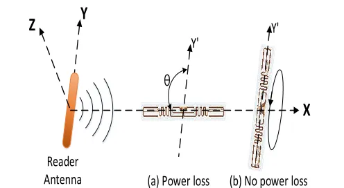
B. Power Loss from Antenna Orientation Mismatch In general work scenarios, tagged objects could be oriented in any direction in three-dimensional space. Passive RFID tags harvest energy from radio signals of the RFID reader for their operation. The angle between the tag and reader antenna is at random, and the tag could become unreadable at certain angles due to power loss from antenna orientation mismatch. If there is a significant power loss in harvesting energy, tags cannot activate and respond to the reader interrogation. If the tag antenna is directional and the short side of tag is perpendicular to reader’s antenna axis, the power received by the tag tends to be zero (Fig. 1(a)). The tag parallel to reader’s antenna axis receives the maximum power from the reader antenna (Fig. 1(b)). The one-way power loss factor (PLF) [20] and power loss in dB are:
Power Loss Factor (PLF) =
cos(
)
(1)Power Loss (PL) in dB =
116 where is the angle between the reader antenna axis and the
direction of tag’s long side (Fig. 1(a)). In the short-side direction of the tag, the power loss is infinite at
= 90o while there is no power loss (PL = 0 db) in the long-side direction at
= 0o. We measured in our laboratory the received signal strength at different tag orientations (Error! Reference source not found.). All measurements were performed at the same distance of 2 meters from the reader antenna, repeated 150 times for each orientation, and averaged. Zero power is obtained at orientations around 90, making the tag unreadable due to complete power loss. To compensate for zero values of PLF, another reader antenna needs to be placed at an angle different from that between the tag and the first antenna. The antennas should be at different angles to avoid the situation when the tag is perpendicular to both reader antennas simultaneously. There are omnidirectional RFID tags that are insensitive to orientation. They have bigger square antennas compared to slim rectangular antennas of directional RFID tags. However, due to the square shape and larger size, omnidirectional tags may be difficult or impossible to attach to small objects.C. Breakpoints
Another source of signal loss for passive tags is due to breakpoints. Breakpoints occur because of multipath fading and cannot be avoided in natural indoor environments [7][8][12]. When a tag is located in a breakpoint, it may be unreadable even within the range of the reader antenna. A tag outside of breakpoints usually produces between 90% to 100%
query response rate (Error! Reference source not found.). A tag within a breakpoint receives insufficient signal power to activate and produces low RSSI values and low query response rates, below 50% and down to 0%, depending on how deep the tag is within a breakpoint.
Query response rate= #of#ofqueryresponsesattemptsfrombythethereadertag (3)
To analyze multipath fading, some studies have used microcell modeling with a ray-based approach [21][22]. A typical ray-based model for the received power is [14]:
d h h g g d P
P r t
t r t r 2 2 sin 4 4 2 2
(4)Where is the wavelength of the RFID frequency, Pr and Pt
are respectively the received and transmitted powers, hr, ht are
the heights of the reader and tag antennas, gr, gt are the
antenna gains, and d is the distance between the tag and reader antenna. In our sensing platform scenario, reader antennas are attached to the ceiling and tags are attached to objects used during work, and both antenna types have fixed gains. Thus, hr, ht, gr, and gt are invariable and Eqn. 4 can be
simplified to Eqn. 5:
d B d A P P t
r 2 2
sin
(5)
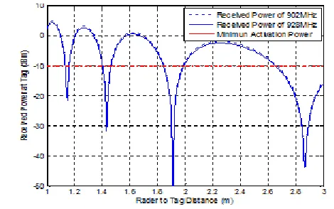
Where A and B are constants. In this model, the parameters that affect the breakpoint locations are the operating frequency and the distance between a tag and a reader antenna. Based on Eqn. 5, we modeled the breakpoints in Error! Reference source not found. according to the distance between the antenna and the tag, with frequencies of 902 and 928 MHz (passive UHF RFID frequency band in the United States is between 902–928 MHz [24]). The UHF RFID band is divided to 50 channels and one of the 50 channels is used randomly for 0.4 seconds. Note that the frequency differences in the UHF RFID band have little effect on the location of breakpoints (Error! Reference source not found.).
Z
Y
X
Reader
Antenna
(a) Power loss
(b) No power loss
θ
Y'
Y'
Fig. 1. Power loss due to the orientation mismatch between a tag and a reader antenna. (a) The tag perpendicular to the reader antenna receives a minimum power, close-to-zero. (b) The tag parallel to the
117 This model, however, does not account for reflections and
defections by small objects and assumes that scatter is produced by large flat surfaces such as walls [6] and the breakpoints could be inconsistent from the actual breakpoints for indoors environment with furniture and other objects. Therefore, we estimate breakpoints by measuring RSSI values in the area of interest. From the examination of the human occlusion the reader antenna is supposed to be located on the ceiling area right above the working area, a patient bed, for the setting. We measured RSSI values with the reader antenna at four different locations that make angle diversity for tackling the antenna orientation mismatch problem. The four locations are right above one third and two third of two long sides of the working area rectangle. The measurement of the signal strength takes place within the area of interest to track tagged objects with uninterrupted reading of passive RFID tags. Fig. 5 shows RSSI versus distance from the four observed locations; zero RSSI values indicate breakpoints.
Because antenna heights and gains are fixed and only the antenna location of the working area is changed within the area of interest, the varying of the breakpoints from the four observed locations remains within 8 cm. Experimentally measured breakpoints from the four locations appear at 0.28 and 1.08 meters with a tolerance of ±4 cm. From this measurement we then define the location of breakpoints and the reader antenna coverage on the patient bed height level to design the sensing platform. The location of breakpoints is 0.28 m from the reader antenna and the antenna coverage is considered to be 1.01 m (Fig. 6(b)). We include a margin for stability because the distance between the end of the second breakpoint (110 cm) and the actual coverage boundary (130 cm) is quite short with close-to-zero-power areas. Due to breakpoints one antenna for one zone does not fully cover its reading range and another antennas are need to compensate each other’s breakpoints. Breakpoints can be avoided by spatial diversity that employs multiple antennas at different positions. The next section describes our sensing platform design that tackles the above impediments for using passive UHF RFID.
20
00
mm
.
Breakpoint 280 mm Reader Antenna
Patient bed
20
00
mm
740mm.
740 mm
Fig. 6. (a) The size of the patient bed. (b) Top view of reader’s antenna coverage with one breakpoint.
D. Sensing Platform Design
As mentioned, physical phenomena and human occlusion during the handling of tagged objects hinder continuous reading of passive RFID tags. These impediments constrain the location of reader antennas to the ceiling area and require antenna diversity to mitigate the power loss from orientation mismatch and breakpoints. Another constraint is the distance between the reader antenna and the area of interest because the coverage area of interrogation signal is proportional to the distance to the tag(Fig. 6). Single-room indoor environments usually restrict the coverage area. For example, at 1.9 m distance between the reader antenna on the ceiling and RFID tags on a desk, the coverage area is a circle of radius 1 m.
No power outside of beam
Radiation Angle θ Reader Antenna
D (distance)
D Radiustan(/2)
118 Our theoretical solution for antenna configuration is derived to
meet the following requirements:
R1: The area of interest should be completely covered by at least two antennas to achieve (i) angle diversity and eliminate orientation mismatch of the reader and tag antennas, and (ii) spatial diversity to eliminate breakpoints.
R2: Breakpoint regions of different antennas must not overlap to avoid any remaining breakpoints.
R3: The number of antennas should be minimized because of cost and esthetic reasons.
Although our method works for any shape of the area of interest, for simplicity we assume a rectangular area of length
ℓ and width w (Fig. 6(a)); in our target domain of trauma resuscitation ℓ is 2 m and w is 0.75 m. We also assume that the beam pattern of a reader antenna is cone-shaped (Fig. 7) [25], and that all reader antennas have identical coverage (1.01 m radius) and breakpoints (single circle of 0.28 m radius), as shown in Fig. 6(b). To meet Requirements R1–R3 under the given assumptions, we use a geometric approach in determining the adequate number and positions of the reader antennas. Given the identical characteristics of reader antennas, any irregular positioning of antennas would require more than necessary antennas (violating Requirement R3) or would have gaps in coverage (violating Requirement R1). It follows that only a regular positioning of antennas would meet all the requirements (Fig. 8(a)). There are three regular tilings of the plane [23]: the triangular tiling, the square tiling, and the hexagonal tiling, which can be obtained by composition of triangular tiles (Fig. 8(c)). It is known that the hexagonal tiling (and, by extension, the triangular tiling) produces the densest circle packing in the plane [23], which means that it packs the greatest number of antennas of all regular tilings. To meet
Requirement R3, we chose the square tiling to cover the area of interest which produces the least dense circle packing. Therefore, we met Requirements R1–R3, addressing the problems of breakpoints and orientation mismatch (Fig. 8(d)).
4 Experimental Results
A. Hardware Setup for the Sensing Platform
119 B. Experimental Results for Angle Diversity
To verify the antenna angle diversity for the area of interest around the patient bed, we measured how RSSI’s depends on tag’s orientation at points A, B and C (Fig. 9). Points A and B were chosen within the area of interest at the greatest distance from the diversity antennas. Angle differences at larger distances are smaller, which means that points A and B were the worst-case points for angle diversity. Point C was chosen so that two antennas (#1 and #2) and the tag were lying on a line, although the tag was at a lower height. Point C was also in the range of antennas #3 and #4 (Fig. 9), which were other diversity antennas for this point. Since other points
in the area of interest were symmetrical relative to the reader antennas (Fig. 9), Points A, B and C represented all the worst-case points for angle diversity. Fig. 10 shows how RSSI depends on tag orientation at these three points. The RSSI was measured 150 times at orientation increments of five degrees and then averaged. Zero RSSI indicated zero power due to complete power loss from antenna orientation mismatch. None of zero RSSI angles at Points A, B and C overlapped. Therefore, our sensing platform eliminated zero-power points for all orientations of the tag in the area of interest.
C. Experimental Results for Breakpoint Cancellation We measured the four circular breakpoints in the area of interest (the patient bed) cvered by the four antennas (Fig. 8(d)). The measurements were obtained so that one antenna at a time was activated and a tag was moved along the y-axis on a grid (Fig. 11) over the patient bed, with tag’s long side facing the active antenna. For each location, query response rate was acquired with 500 trials. Breakpoints were identified as the points where the measured query response rate (Eqn. 3) was below 25%. Finally, all four antenna centers were aligned, and their breakpoints superimposed to specify the maximum areas of breakpoints. The furthest breakpoints occurred at about 36 cm from an antenna (Fig. 11). Therefore, if the distance between antennas is greater than 72 cm, there will be no overlaps of breakpoints. Because in our sensing platform (Fig. 8(d)) the antennas are at 75 cm apart from each other,
their breakpoints did not overlap and Requirement R2 from Section 3.D was fully met. Note that the widest breakpoints appeared about 8 cm wide along the central direction of each antenna beam (Fig. 11), facing the center of the patient bed (Fig. 8(d)). The breakpoints on edge directions of the bed were sparse and narrow. The bed edges were less affected with breakpoints, because they experienced fewer reflected radio signals than the central area of the bed.
5 Conclusion
120 within their coverage area, rendering them inadequate for
continuous tracking of tags. We identified the causes of the power loss as breakpoints and antennas angle mismatch between the reader and a randomly oriented tag. Breakpoints are created from indoor radio signal propagation and cannot be avoided. We presented a UHF RFID sensing platform that addresses the power loss problems using angle and spatial diversity. Our design provides uninterrupted coverage of the area of interest, eliminating the power loss problems and allowing continuous tracking of tags. We applied this sensing platform in a hospital trauma bay. We measured RSSI and query response rates for breakpoints and angle mismatch, and found no points with significant power loss. We conclude that this sensing platform provides uninterrupted tracking of RFID-tagged objects in indoor settings.
References
[1] M. Buettner, R. Prasad, M. Philipose, and D. Wetherall, ―Recognizing daily activities with RFID-based sensors,‖ in Proc. 11th Int’l Conf. Ubiquitous Computing, 2009, pp.51-60.
[2] S. Parlak and I. Marsic, ―Detection object motion using passive RFID: A trauma resuscitation case study,‖ IEEE Trans. Instrum. Meas., vol.62, no.9, pp.2430-2437, Sept 2013.
[3] S. Parlak, S. Ayyer, Y.Y. Liu, and I. Marsic, ―Design and evaluation of RFID deployments in a trauma resuscitation bay,‖ IEEE J. Biomed. Health Informatics, vol.18, no.3, pp.1091-1097, May 2014.
[4] L. Yang, Y. Chen, X. Li, C. Xiao, M. Li, and Y. Liu, ―Tagoram: Real-time tracking of mobile RFID tags to high precision using COTS devices,‖ in Proc. 20th ACM Annual Int’l Conf. on Mobile Computing and Networking, 2014, pp. 237-248.
[5] Alien Technology, Inc., http://www.alientechnology.com/
[6] S.R. Banerjee, R. Jesme, and R.A. Sainati, ―Performance analysis of short range UHF propagation as applicable to passive RFID,‖ in Proc. IEEE RFID Conference, 2007, pp. 30-36.
[7] D. Kim, M.A. Ingram, and W.W. Smith, ―Measurements of small-scale fading and path loss for long range RF tags,‖ IEEE Trans. Antennas Propagat., vol.51, no.8, pp.1740-1749, Nov 2003.
[8] L.W. Mayer, M. Wrulich, and S. Caban, ―Measurements and channel modeling for short range indoor UHF applications,‖ in Proc. European Conf. Antennas and Propagat., 2006.
[9] J.E. Bardram, A. Doryab, R.M. Jensen, P.M. Lange, K.L.G. Nielsen, and S.T. Petersen, ―Phase recognition during surgical procedures using embedded and body-worn sensors,‖ in Proc. IEEE Int’l Conf. Pervasive Comput. Commun., 2011, p.45-53.
[10]K. Ohashi, S. Ota, L. Ohno-Machado, and H. Tanaka, ―Smart medical environment at the point of care:
Auto-tracking clinical interventions at the bed side using RFID technology,‖ Computers in Biology and Medicine, vol. 40, no. 6, pp. 545-554, 2010.
[11]D. Dobkin, ―Indoor propagation issues for wireless LANs,‖ RF Design, pp 40-46, Sept 2000.
[12]P.V. Nikitin and K.V.S. Rao, ―Antennas and propagation in UHF RFID systems,‖ in Proc. IEEE Int’l Conf. RFID, Las Vegas, NV, 2008, pp. 277-288.
[13]D. Joho, C. Plagemann, and W. Burgard, ―Modeling RFID signal strength and tag detection for localization and mapping,‖ in Proc. IEEE Int’l Conf. Robotics Automat., 2009.
[14]S.C.M Perera, A.G. Wiliamson and G.B. Rowe, ―Prediction of breakpoint distance in microcellular environments,‖ Electronics Letters, vol.35, no.14, pp.1135-1136, July 1999.
[15]A. Chattopadhyay and A. Harish, ―Analysis of low range indoor location tracking techniques using passive UHF RFID tags,‖ in Proc. 2008 IEEE Radio and Wireless Symposium, Jan 2008, pp. 351-354.
[16]J.S. Choi, H. Lee, R. Elmasri and D.W. Engels, ―Localization systems using passive UHF RFID,‖ in Proc. 5th Int’l Joint Conf. INC, IMS and IDC, Aug 2009, pp.1727-1732.
[17]A. Nemmaluri, M.D. Corner, and P. Shenoy, ―Sherlock: Automatically locating objects for humans,‖ in Proc. ACM MobiSys, 2008, pp.187-198.
[18]P. Turaga, R. Chellappa, V. Subrahmanian and O. Udrea, ―Machine recognition of human activities: A survey,‖ IEEE Trans. Circuits Syst. Video Technol., vol.18, no.11 pp.1473-1488, 2008.
[19]S. Parlak, A. Sarcevic, I. Marsic and R.S. Burd, ―Introducing RFID technology in dynamic and time-critical settings: Requirements and challenges,‖ J. Biomed. Informatics, vol.45, no.5, pp.958-974, 2012.
[20]K. Finkenzeller, RFID Handbook, 3rd ed.: A John Wiley and Sons, Ltd., Publicaion, 2010, pp. 76-83.
[21]A.J. Rustako, Jr., N. Amitay, G.J. Owens and R.S. Roman, ―Radio propagation at microwave frequencies for line-of-sight microcellular mobile and personal communications,‖ IEEE Trans. on Vehi. Tech., vol.40, no.1, pp.203-210, Feb 1991.
[22]S.Y. Tan and H.S. Tan, ―Improved three dimensional ray tracing technique for microcellular propagation models,‖ Electronics Letters, vol.31, no.17, pp.1503-1505, Aug 1995.
[23]Wikipedia page on tiling by regular polygons: http://en.wikipedia.org/wiki/Tiling_by_regular_polygons
121 [25]D.M. Dobkin, ―Tutorial: Radio basics for UHF RFID,‖ EE
Times, July 2008.
[26]EPC/RFID Standards, online at: http://www.gs1.org/epc-rfid