Forestry & Natural-Resource Sciences Last Correction: Apr. 4, 2019
SPECIAL ISSUE ON SELECTED EXAMPLES OF RECENT
TRENDS IN COMPUTING
M. Rajesh
∗ 1, V. Kannan
1, C.J. Cieszewski
21 ∗
Corresponding Guest Editor; Dept of Computer Science and Engineering, KRS College of Engineering, India
2
Guest Editor, Institute for Artificial Intelligence, University of Georgia, Athens, GA, USA
Abstract. The presented here a collection of conference papers is a Special Volume on Recent Trends
in Computing that was compiled by the editors for the Mathematical and Computational Forestry & Natural-Resource Sciences (MCFNS) journal. The creation of this Special Issue and the Special Section, which contains it, was requested by the organizers of the International Conference on Recent Trends in Computing (ICRTC-2017), held on Dec. 14–15, 2017, at the SRM Institute of Science and Technology (formerly SRM University) on the NCR Campus, Tamil Nadu, India. The purpose of the Special Section hosting this volume is to contain publications originated from this and other similar scientific endeavors involving research on developments of computing technology as relevant to various Computational Sciences associated with natural resources or related to their research and management. In the current issue, dedicated in its entirety to this conference, we present a set of the papers in this category, which includes 29 selected examples of research that have been reviewed externally by the conference organizers.
Keywords: Advanced Computing; Networking; Informatics; Security and Privacy; Trends in Com-puting;
Part I
Editor’s Introduction
1
Conference overview
The scope of the International Conference on Recent Trends in Computing encompasses the fundamental and applied research topics, which deal with various areas of Advance Computing, Networking, Informatics, Security and Privacy, in applications of computing technologies. The conference aims to bring together academic scien-tists, research scholars, and students, to share and dis-seminate their research and findings in broadly scoped scientific research topics related to computing, network-ing, and informatics, and to discuss the practical chal-lenges encountered in the adaptation of the set forth solutions. The conference provides the authors and par-ticipants with opportunities for national and interna-tional collaboration and networking among universities and institutions from India among other countries, for promoting research and technology development. The conference endeavors to promote the implementation of
basic research into applied investigations and to transfer the applied investigation results into practice implemen-tations.
Papers included in this issue stem from the 2017 con-ference (ICRTC-2017), organized by the Department of Computer Science Engineering, held on Dec. 14–15, 2017, at the SRM Institute of Science and Technol-ogy (formerly known as SRM University), NCR Cam-pus, Tamil Nadu, India. Two Guest Editors: M. Ra-jesh, Dept of Computer Science and Engineering, KRS College of Engineering, India; and V. Kannan, Manag-ing Director, CLDC Research and Development, Coim-batore, Tamilnadu, India, made the selection of the manuscripts for this Special Issue and oversaw the re-view and copyediting of the selected for publication manuscripts. One editor, C.J. Cieszewski, wrote this in-troduction and prepared the volume for publication with limited editing of individual manuscript and typesetting of this volume. The topics of consideration for the pub-lication manuscripts related to the conference program are divided into four Tracks covering the areas of “Ad-vanced Computing”, “Networking”, “Informatics”, and “Security and Privacy”.
In the area of Advanced Computing, we find top-ics related to Pattern Recognition, Image Processing and Analysis, Virtual Reality, Document Image Pro-cessing, Evolutionary Algorithms, Ubiquitous Comput-ing, Web minComput-ing, Perceptual ComputComput-ing, and other re-lated topics. The area of Networking covers Network Performance Analysis, Fault-Tolerant Systems, Parallel and Distributed Networks, Routing Protocol and Archi-tecture, Network Dependability, Network Optimization, End-to-end resilience, Quality of service, and related topics. The area of Informatics includes Database and Query Processing, Expert Systems, Data Security, Data Privacy Preserving Techniques, Information Retrieval, Knowledge Discovery, Semantic Web, and related top-ics. Finally, the area of Security and Privacy contains the subareas of Access Control and Authorization, At-tacks and Defenses, Anonymity, Security and Privacy for the IoT and 5G, Intrusion Detection and Malware Anal-ysis, Vulnerability Analysis and Assessment, Secure Pro-tocols and Design, Security and Privacy Measures and Policies, Privacy-Preserving Data Publishing & Mining, Wireless Network System and Security, Usable Security and Privacy, Biometric Security Systems, Identity and Trust Management, Critical Infrastructures, Key Man-agement, Fraud Detection, Pervasive Security, Security for Wearable and Haptic Technology, and other related topics.
2
Conference organization
The conference organization was based on several Pro-gram functions and Committee activities. The Chief Pa-tron was Dr. T.R. Pachamuthu, Chancellor, SRM Uni-versity, India. The Convenor was Dr. R.P. Mahapa-tra, Prof. & HOD SRM University, India. Two con-ference secretaries were: (a) Rajarajan Muttukrishnan, City University London, UK; and (b) M. Mohan, As-sist. Prof., Dept CSE, SRM University, India. The four Program Committee Chairs, Patrons, Coordinators, and Advisory and Technical Committees’ members are listed below.
1. Technical Program Committee Chairs
(a) Dr. Hyoung-Nam Kim, Prof., Dept. of Elec-tronics Engineering, Pusan National Univer-sity (PNU), Korea
(b) Sanjeevi Kumar Padmanaban, SMIEEE, Uni-versity of Johannesburg, South Africa
(c) Dr. Jagadeesh Pasupuleti, Universiti Tenaga Nasional, Malaysia
(d) Prof. M. Rajesh, Dept of CSE, KRS College of Engineering, India
2. Patrons
(a) Ravi Pachamoothoo, Chairman, SRM Groups, India
(b) Prof. P. Sathyanarayanan, President, SRM University, India
(c) Prof. Prabir K Bagchi, Vice Chancellor, SRM University, India
(d) Dr. Manoj Kumar Pandey, Director, SRM University, NCR Campus, India.
(e) Dr. S. Viswanathan, Deputy Registrar, SRM Groups, India.
3. Coordinators
(a) Dr. Jitendra Singh, Asso. Prof, Dept CSE, SRM University, India
(b) P. Velmurugan, Assit. Prof, Dept CSE, SRM University, India
(c) Mohanraj Ramasamy, Assit. Prof, Dept CSE, SRM University, India
4. Advisory Committee
(a) Audun Josang, Oslo University, Norway
(b) Greg Gogolin, Ferris State University, USA
(c) Ljiljana Brankovic, The University of Newcas-tle, Australia
(d) Dr. KannanJegathala Krishnan, University of Melbourne, Australia
(e) Dr. R. Malathi, Annamali Unviresity, India
5. Technical Committee
Prof. K.T. Arasu, Wright State University Dayton, Ohio, North America
Dr. Mohammad Ayoub Khan, Taibah Uni-veristy, Kindom of Saudi Arabia
Dr. Rumyantsev Konstantin, Southern Federal University, Russia
Dr. Wen-Juan Hou, National Taiwan Normal University, Taiwan
Prof. Syed Akhat Hossain, Daffofil University, Dhaka, Bangladesh
Dr. Zoran Bojkovic, University of Belgrade, Serbia
Dr. Sophia Rahaman, Manipal University, Dubai
Dr. Thippeswamy Mn, University of KwaZulu-Natal, Durban
Dr. Wei Wang, Xi’an Jiaotong-Liverpool Uni-versity, China
Dr. Mohd. Helmey Abd Wahab, UniversitiTun Hussein Onn, Malaysia
Dr. Andrew Ware, University of South Wales, United Kingdom
Dr. Shireen Panchoo, University of Technol-ogy, Mauritius
Dr. Sumathy Ayyausamy Manipal University, Dubai
Prof. Dharm Singh, Namibia University of Sci-ence and Technology, Namibia
Dr. Adel Elmaghraby, University of Louisville, USA
Dr. Almir Pereira Guimaraes, Federal Univer-sity of Alagoas, Brazil
Dr. Fabrice Labeau, McGill University, Canada
Dr. Abbas Karimi, Faculty of Engineering, IAU, Arak, Iran
Dr. Kaiyu Wan, Xi’an Jiaotong-Liverpool Uni-versity, China
Prof. Pao-Ann Hsiung, National Chung Cheng University, Chiayi, Taiwan
Dr. Paul Macharia, Data Manager, Kenya
Dr. Yong Zhao, University of Electronic Sci-ence & Technology of China, China
Dr. Upasana G Singh, University of kwazulu-Natal, South Africa
Dr. Basheer Al-Duwairi, Jordan University Of Science and Technology, Jordan
Dr. M. Najam-ul-Islam, Bahria University, Pakistan
Dr. Ritesh Chugh, CQ University Australia
Dr. Yao-HuaHo, National Taiwan Normal Uni-versity, Taiwan
Dr. Pawan Lingras, Saint Mary’s University, Canada
Dr. Poonam Dhaka, University of Namibia (UNAM), Namibia
Dr. Amirrudin Kamsin, University of Malaya, Kuala Lumpur, Malaysia
Dr. Indra Seher, CQ University Sydney, Aus-tralia
Prof. Adel Elmaghraby, University of Louisville, USA
Prof. Sung-Bae Cho, Yonsei University, Seoul, Korea
Dr. Dong Fang, Southeast University, China
Dr. Huy Quan Vu, Victoria University, Mel-bourne, Australia
Dr. Basheer Al-Duwairi, JUST, Jordan
Dr. Sugam Sharma, Iowa State University, USA
Dr. Yong WANG, University of Electronic Sci-ence & Technology of China, China
Dr. T.G.K. Vasista, King Saud University, Riyadh, Saudi Arabia
Dr. Nalin Asanka Gamagedara Arachchilage, University of New South Wales, Australia
Dr. Durgesh Samadhiya, National Applied Re-search Laboratories, Hsinchu Taiwan
Dr. Akhtar Kalam, Victoria University, Aus-tralia
Dr. Ajith Abraham, Director, MIR Labs, USA
Dr. Runyao DUAN, Tsinghua University, China
Dr. Miroslav Skoric, IEEE Section, Austria
Dr. Al-Sakib Khan Pathan, IIU, Malaysia
Dr. ArunitaJaekal, Windsor University, Canada
Dr. Pei Feng, Southeast University, China
Dr. Durga Toshniwal, IIT Roorkee
Dr. Satinder Kumar Sharma, IIT-Mandi
Dr. Ashish Anand, IIT-Guwahati
Dr. Somnath Dey, IIT-Indore
Prof. R.B. Mishra, Indian Institute of Technol-ogy, IIT (BHU), India
Dr. Raman Balasubramanian, IIT Roorkee, India
Dr. Bhaskar Bisawas, Indian Institute of Tech-nology, IIT (BHU), India
Dr. Rashmi Dutta, IIT-Guwahati
Dr. Abhishek Srivastava, IIT-Indore
Dr. Gaurav Harit, IIT-Jodhpur
Dr. Naveen Chauhan, National Institute of Technology, NIT-Hamirpur
Dr. Dilbag Singh, National Institute of Tech-nology, NIT-Jalandhar
Dr. Lillie Dewan, National Institute of Tech-nology, NIT-KUK
Dr. S.R. Balasundaram, National Institute of Technology, NIT-Trichy
Dr. Animesh Dutta, National Institute of Technology, NIT-Durgapur
Prof. Lalit K. Awasthi, National Institute of Technology, NIT-Hamirpur
Dr. Nagamma Patil, National Institute of Technology, NIT-Suratkal
Dr. Dilip Singh Sisodia, National Institute of Technology, NIT-Raipur
Dr. Alak Majumdar, National Institute of Technology, NIT-Arunchal Pradesh
Dr. Taimoor Khan, National Institute of Tech-nology, NIT-Silchar
Dr. Madhu, National Institute of Technology, NIT-Hamripur
Dr. Anurag Singh, National Institute of Tech-nology, NIT-Delhi
Dr. Shashidhar G Koolagudi, National Insti-tute of Technology, NIT-Surathkal
Dr. Anmol Ratna Saxena, National Institute of Technology, NIT-Delhi
Dr. Pardeep Singh, National Institute of Tech-nology, NIT-Raipur
Dr. P. Chinnamuthu, National Institute of Technology, NIT-Nagaland
Dr. Narottam Chand, NIT Hamirpur
Dr. Vikram Goyal, IIIT Delhi, India
Prof. Anurag Srivastava, IIIT, Gwalior, M.P.
Dr. Radhey Shyam, Scientist, National Infor-matics Center, NIC-India
Dr. Karan Singh, School of Computer & Sys-tems Sciences, JNU, Delhi
Dr. B.B. Sagar, Birla Institute of Technology, BITS- Ranchi
Dr. M. Kumar, Senior Project Engineer, CDAC-Noida
Dr. Vijay Singh Rathore, Chairman CSI, Jaipur-Chapter
Dr. Satish Chandra Tiwari, Cadence Design Systems, Noida
Prof. K N Mishra, Birla Institute of Technol-ogy, BITS-Ranchi
Dr. Salim Beg, AMU Aligarh
Dr. Karan Singh, JNU, Delhi
Dr. C.K. Jha, Banasthali University, Ra-jasthan
Prof. Vibhakar Mansotra, University of Jammu, Jammu
Dr. Kanwa lGarg, Kurukshertra University, Haryana
Dr. Babita Pandey, Lovely Professional Uni-versity, Punjab
Dr. Karan Singh, School of Computer & Sys-tems Sciences, JNU, Delhi
Dr. Saleena B., SCSE, VIT University, Vellore, Tamil Nadu
Dr. B.B. Sagar, Birla Institute of Technology Mesra Ranchi, India
Prof. Manu Sood, Himachal Pradesh Univer-sity Shimla, H.P
Dr. M. Karthikeyan, Tamilnadu College of En-gineering, Coimbatore
Dr. Shailendra Narayan, Amity School of En-gineering & Technology, Noida
Dr. Saira Banu J., VIT University, Vellore, Tamil Nadu
Dr. A. Prakash Singh, GGSIPU, Delhi, India
Dr. Anurag Jain, GGSIPU, Delhi, India
Prof. Jaisankar N., Prof., SCSE, VIT, Vellore, Tamil Nadu
Prof. V Bsingh, Delhi University, New Delhi
Prof. Reena Dadheech, University of Kota, Ra-jasthan
Prof. O P Rishi, University of Kota, Rajasthan
Prof. Rakesh Kumar, Kurukshetra Univesity, Haryana.
Dr. Jamuna Kanta Sing, Jadavpur University, West Bengal
Dr. Amit Prakash Singh, IP University, Delhi, India
Dr. Karan Singh, JNU, Delhi, India
Prof. Amay Kumar Rath, DRIEMS, Cuttack
Dr. Anurag Seetha, Dr. CV Raman University, Bhopal
Dr. Siddharth Ghosh, Keshav Memorial Insti-tute of Technology, Hyderabad
N. Subramanian, Proj. Manager, Analog De-vices, USA
A. Nagarajan, JNTU, AP
Nalla Anandkumar, SETS
Kuldeep Singh, Scientist-E, (DRDO)
Prof. J. Amudhavel, CSE (R&D), KL Univer-sity, A.P
Dr. K. Thirumalaivasan, ACET, Puducherry
Dr. K. Ramash Kumar, VIT, A.P.
Dr. G. Zayaraz, PEC, Pondicherry.
Dr. N. Alagumurthi, PEC, Puducherry
Rajesh, KRSC, India
Sathish Kumar, DRDO
P. Gurunathan, UAE
3
Organization of the proceedings
Part II
Selected conference papers
Contents
I
Editor’s Introduction
1
II
Selected conference papers
6
A SINGLE STAGE THREE PHASE INVERTER BASED ON CUK CONVERTER FOR PV APPLI-CATION
P. Sivakumar, M.S. Ramkumar, A. Amudha, K. Bal-achander, D. Kavitha . . .
9
MAXIMUM POWER POINT TRACKING
STRATEGY FOR A NEW WIND POWER SYS-TEM WITH SUPER CAPACITOR CONNECTED
PHOTOVOLTAIC POWER GENERATION
SYS-TEM AND SUPPORTED TO A DISTRIBUTION POWER GRID
E. Jaiganesh, G. Emayavaramban, A. Amudha, K. Balachander, D. Kavitha . . .
14
MODELING, DESIGN AND IMPLEMENTATION
OF A POWER CONVERSION SYSTEM FOR
WECS BY USING FUZZY BASED MPPT
V. Suresh, G. Emayavaramban, A. Amudha, K. Bal-achander, D. Kavitha . . .
26
INTELLIGENT POWER TRACKING
ALGO-RITHM USING ANFIS AND ZETA CONVERTER S. Nandhini, D. Kavitha, S. Kalaiarasi, A. Amudha, M. Siva Ramkumar . . .
38
ANALYSIS OF NEW NOVELTY MULTILEVEL
INVERTER CONFIGURATION WITH BOOST
CONVERTERS FOR A PHOTOVOLTAIC SYSTEM WITH MPPT
S. Senthil Kumar, D. Kavitha, A. Amudha, G. Emayavaramban, M. Siva Ramkumar . . .
46
NON ISOLATED INTERLEAVED CUK
CON-VERTER FOR HIGH VOLTAGE GAIN APPLICA-TIONS
D. Kavitha, M. Siranjeevi, K. Balachander, M.S. Ramkumar, M.S. Krishnan . . .
58
PV AND FUEL CELL BASED DYNAMIC VOLT-AGE RESTORER FOR LVRT IMPROVEMENT OF DFIGWTS
R. Shobana, K. Balachander, A. Amudha,
G. Emayavaramban, M. Siva Ramkumar . . .
63
A FUZZY LOGIC APPROACH TO MICROGRID DEMAND RESPONSE IN BOTH OFFLINE AND ONLINE MODE
P. Srinivasan, K. Balachander, A. Amudha, G. Emayavaramban, M. Siva Ramkumar . . .
72
ANALYSIS AND ENERGY EFFICIENCY OF
SMALL-SCALE WIND ENERGY CONVERSION SYSTEM USING ADAPTIVE NETWORK BASED
FUZZY INTERFERENCE SYSTEM (ANFIS)
OF MAXIMUM POWER POINT TRACKING
METHOD
R. Veluchamy, K. Balachander, A.Amudha, M. Siva Ramkumar, G. Emayavaramban . . .
83
MULTI CONVERTER UNIFIED POWER QUAL-ITY CONDITIONING (MC-UPQC) FOR VARI-OUS LOADS WITH ANN APPROACH TO TWO SOURCE CONCEPT
K. Suresh Kumar, K. Balachander, A. Amudha, M. Siva Ramkumar, D. Kavitha . . .
93
CASCADE COCKCROFT-WALTON VOLTAGE
MULTIPLIER APPLIED TO
DESIGN AND IMPLEMENTATION OF SERIES Z-SOURCE MATRIX CONVERTERS
S. Vivekanandan, M.S. Ramkumar, A. Amudha, M.S. Krishan, D. Kavitha . . . .
110
DTC-SVM MANAGEMENT OF INDUCTION MA-CHINE FED BY 3 LEVEL NPC MATRIX CON-VERTOR
A. Thirugnanaselvi, M.S. Ramkumar, A. Amudha, M.S. Krishan, K. Balachander . . . .
116
A PHOTOVOLTAIC GENERATION SYSTEM
BASED ON HYBRID MULTILEVEL INVERTER IN ORDER TO REDUCE SWITCHING FOR DC MICRO GRIDS
C. Karunamoorthy, A. Amudha, K. Balachander, M. Siva Ramkumar . . . .
121
TRANSIENT STABILITY IMPROVEMENT IN POWER SYSTEM WITH SMES AND BATTERY ENERGY STORAGE SYSTEM
C. Chinnusamy, G.Emayavaramban, A. Amudha, K. Balachander, M. Siva Ramkumar . . . .
132
ACHIEVING EFFICIENT AND SECURE DATA
ACQUISITION FOR CLOUD-SUPPORTED
IN-TERNET OF THINGS IN GRID CONNECTED SO-LAR, WIND AND BATTERY SYSTEMS
M. Jayaprakash, D. Kavitha, M. Siva Ramkumar, K. Balachander, M. Sivaram Krishnan . . . .
144
GRID CONNECTED WIND ENERGY CONVER-SION SYSTEM WITH UNIFIED POWER QUAL-ITY CONDITIONER (UPQC) BY FUZZY LOGIC M. Mohammed Shaheeth, D. Kavitha, A. Amudha, M. Siva Ramkumar, K. Balachander, G. Emayavaram-ban . . . .
156
INTEGRATED DC/DC PARALLEL MAXIMUM
POWER POINT TRACKING BASED
PHOTO-VOLTAIC SYSTEM ARCHITECTURE FOR COM-MON DC BUS
V. Akiladevi, A. Amudha, K. Balachander, M. Siva Ramkumar, S. Divyapriya . . . .
169
INTEGRATION OF VARIOUS RENEWABLE
ENERGY SYSTEMS WITH BATTERY ENERGY STORAGE SYSTEM USING OPTIMAL ENERGY
MANAGEMENT SYSTEM
G. Sumathi, A. Amudha, K. Balachander . . . .
179
ANALYSIS AND PARALLEL OPERATION OF NOVEL BIDIRECTIONAL DC-DC CONVERTER FOR DC MICROGRID
K. Kaleeswari, K. Balachander, A. Amudha, M. Siva Ramkumar, D. Kavitha . . . .
190
AN EFFICIENT HIGH STEP UP CONVERTER
FOR AUTOMOBILE APPLICATIONS USING
FUZZY LOGIC CONTROL TECHNIQUE
T. Kalimuthu, K. Balachander, A. Amudha, G. Emayavaramban, M. Siva Ramkumar . . . .
201
COMPENSATION OF VOLTAGE VARIATIONS IN DISTRIBUTION SYSTEM DURING FAULT CON-DITION BY USING SEPARATE ENERGY STOR-AGE DEVICE BASED DVR
N.A. Sankar, K. Balachander, A. Amudha, S. Di-vyapriya, M. Siva Ramkumar . . . .
209
IMPLEMENTATION OF HARMONIC MITIGA-TION OF GRID CONNECTED MODIFIED MLI FOR VARIABLE-SPEED WIND ENERGY CON-VERSION SYSTEM
D. Sivakumar, A. Amudha, K. Balachander, M. Siva Ramkumar . . . .
223
POWER GRID CONNECTED SEMI-Z SOURCE INVERTER SUPPLIED BY PHOTOVOLTAIC AND WIND SYSTEM WITH A NEW MODULATION STRATEGY
D. Babu, A. Amudha, K. Balachander, G. Emayavaram-ban, M. Siva Ramkumar . . . .
231
A HIGH GAIN INPUT-PARALLEL
OUTPUT-SERIES DC/DC CONVERTER WITH
DUALCOUPLED-INDUCTORS
Kalimuthu, M. Siva Ramkumar, A. Amudha, K. Bal-achander, M. Sivaram Krishnan . . . .
242
A SINGLE STAGE THREE PHASE INVERTER BASED ON
CUK CONVERTER FOR PV APPLICATION
P. Sivakumar, M.S. Ramkumar, A. Amudha, K. Balachander, D. Kavitha
Abstract: This project presents a replacement three-phase converter supported the Cuk converter. The principal feature
of the planned topology is that the energy storage parts, like inductors and capacitors, is reduced therefore on boost the trustworthiness, and reduce the size and total value. The buck-boost inherent characteristic of the Cuk device, reckoning on the time-varying duty magnitude relation, provides flexibility for stand alone and grid-connected applications once the required output ac voltage is lower or larger than the dc aspect voltage. Average large and little signal models are accustomed to studying the Cuk converter’s nonlinear operation. The essential structure, management vogue, and MATLAB/SIMULINK results are given.
Keywords: Buck-boost inverter, Cuk converter, dc–dc converters, proportional integral (PI) control, pro-portional resonant (PR) control, state space averaging, switched mode power supply (SMPS).
1
Introduction
The ´Cuk device can be a form of DC-DC device that has Associate in Nursing output voltage magnitude that’s either larger than or however the input voltage magnitude, with Associate in Nursing opposite polarity. It uses a capacitance as its main energy-storage half, in distinction to most different varieties of converters that use Associate in nursing inductance. This paper proposes a spanking new three half converter supported three bifacial 2-switch 2 diode Cuk converters with Asso-ciate in Nursing nonobligatory very little dc-link capac-itance Associate in Nursing describes an acceptable and wise management structure that may bemused with ef-ficiency in business applications. The planned converter is expedient for the PV applications, where the peaks of the output ac currents unit of measurement required to be flexible over and below the input DC for MPPT oper-ation and for providing simple paralleling at the PCC. A phase converter converts a DC input into a three-phase AC output. [1–5]Its three arms unit of measure-ment unremarkably delayed by Associate in the nursing angle of 120°therefore on generates an AC give. The elec-trical converter switches each contains magnitude rela-tion of fifty and modificarela-tion happens once every T/6 of the time T (60°angle interval). The figure below shows a circuit for a three half converter. It’s nothing but three single half inverters convey identical DC provides. The pole voltages in A passing three half converter are ade-quate the pole voltages in single half [*fr1] bridge con-verter. There is a trend toward normally structured re-newable/distributed system ideas thus on crop costs and provide high reliableness. This trend affects dc–ac
con-verter topologies significantly concerning reducing the scale and kind of converter passive components. For dc-to-ac conversion, the quality voltage provides (VSI) is that the foremost typical convertor topology. The volt-age provides inverters (VSI) are classified on the premise of their construction and their output voltage and their level of implementation. There are three main varieties of the VSI on the premise of their output voltage as: 1) Single-phase half-bridge converter 2) single-phase full-bridge converter three) 3 half voltage provides converter A. Single half [*fr1] bridge voltage provides the push-pull kind convertor has some disadvantages. It desires the dual power provide for the operation of transistors. Together equipped VSI desires the 2 completely different kinds of transistors, like NPN and PnP, and every the transistors have utterly different switch speed. Owing to these a pair of disadvantages MOSFETs is used within the circuit. The sole half VSI created victimization the MOSFET. The sole half voltage provides converter con-sists of two MOSFET. The MOSFET square measure works a bit like the switches. In bridge topology, the in-put DC voltage is symmetrically divided due to identical capacitors connected across the DC provide.
2
Existing System
de-pends on the duty relation equally as device parameters this can increase management vogue quality as a result of the device poles and zeros travel through a given phys-ical phenomenon. In addition, the time-varying transfer performs ends up in output voltage and current distor-tion [6–10].
3
Planned System
In this project, a three-phase dc–ac Cuk converter-based current offer convertor has been planned and as-sessed. The state house averaging methodology was used to vogue the management structure. An extra management loop reduced distortion with low passive half values. Satisfactory winds up in terms of reduced second-order harmonic components inside the output currents and voltages were obtained. Generally, high-order converters like Cuk converters square measure avoided in convertor applications because of their man-agement quality. The planned single-stage three-phase Cuk-based convertor introduces several deserves once used for PV applications. The planned single-stage three-phase Cuk-based convertor introduces several de-serves once used for PV applications. Continuous input current permits direct MPPT techniques and addition-ally the power of paralleling dc–ac convertors at identical PCC promote the planned device as viable topology for PV applications [11–16].
4
Cuk device
A DC to DC converter takes the voltage from a DC offer and converts the voltage of providing into another DC voltage level. They are the accustomed increase or decrease the voltage level. Typically this can be often commonly used cars, transferable chargers, and trans-ferable videodisc players. Some devices would like an exact amount of voltage to run the device. The asso-ciate degree excessive quantity of power can destroy the device, or less power may not be ready to run the de-vice. The converter takes power from the battery and cuts down the voltage level, equally a converter increase the voltage level. As an example, it’d be necessary to step down the power of associate degree outsized bat-tery of 24V to 12V to run a radio. This paper proposes a replacement 3phase convertor supported 3 duplex 2-switch two diode Cuk converters with associate degree optional little dc-link capacitance associate degreed de-scribes an applicable and wise management structure which will be used with efficiency in trade applications. The projected convertor is expedient for the PV appli-cations, where the peaks of the output ac currents are required to be versatile over and below the input DC for MPPT operation and for providing easy paralleling at the PCC. The Cuk converter is used for getting the
output voltage with fully completely different polarity. This means that the output voltage magnitude is going to be either larger or smaller than the input, and there is a polarity reversal on the output. The device on the input acts as a filter for the dc provides, to prevent large harmonic current. Not just like the previous converter topologies where energy transfer is expounded to the de-vice. Energy transfer for the Cuk converter depends on the capacitance
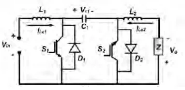
Figure 1: Cuk converter diagram.
The operative modes of a Cuk device are shown in Fig. 1. The equipment consists of the associated input voltage provide Vin, a pair of switches S1 and S2, and a pair of parallel diodes D1 and D2. The energy between the voltages provides and conjointly the load is trans-ferred through condenser C1. The energy is holding on instantly in inductors L1 and L2. the basic operation at steady state could also be delineated simply, once S1 is Off, C1 is charged leading IL1 to decrease, whereas L2 is discharged among the load inflicting IL2 to increase. At future switch quantity, once S1 is On, L1 is charged, and IL1 can increase, whereas C1 is discharged inflicting IL2 to increase. It should be deduced that IL1 and IL2 are reticulate via the energy transfer through C1.
Figure 2: cuk converter waveform.
5
Proposed Diagram
Figure 3: Cuk based three phase inverter.
Figure 4: simulation diagram.
power extension. Each Cuk device builds a curvilin-ear output voltage, specifically current, with a dc offset. Assumptive that the dc and ac voltage ratios between output and input unit of measurement Hdc and Hac, sev-erally, following equation explains the relation between the input and output voltage,
Because of the balanced energy operation of the three phases, it’s positive that the dc offsets of each half unit of measurement off and conjointly the three-phase load encounters pure curvilinear voltages and currents [21– 22].
6
Control Design
The management objective is to trace a predefined actuate output voltage. Vd, Vq, and Vdc unit of mea-surement the direct, quadrature, and dc offset compo-nents of the output voltage at Vc2a, Vc2b, and Vc2c. The subscript [??] refers to a reference worth. Kp and Ki unit of measurement the proportional and integral gains of the proportional integral (PI) controller. The management input is taken into consideration the input voltage Vin. However, normally, the voltage of the PV is constant over a short quantity, relying on the MPPT operation, and thence the management input has to be compelled to be written in terms of the time variable duty relationδ[17–20].
Figure 5: cuk converter.
Figure 6: output waveform.
7
Conclusion
Figure 7: solar pv,iv graph.
low passive element values. Satisfactory winds up in terms of reduced second-order harmonic parts among the output currents and voltages were obtained and verified by MATLAB/SIMULINK. Associate convertor system was accustomed to manufacturing experimental results that confirmed system performance.
References
[1] X. Hu, C. Gong, ”A High Gain Input-Parallel Output-Series DC/DC Converter with Dual Coupled Inductors,” IEEE Trans. Power Electron., vo1.30, no.3, pp.1306, 1317, March 2015.
[2] M. Siva Ramkumar, M. Sivaram Krishnan “Power Management of a Hybrid Solar- Wind Energy Sys-tem” International Journal of Engineering Research & Technology vol. 3(2) pp.1988–1992, 2014.
[3] M. Siva Ramkumar, M. Sivaram Krishnan, Dr. A. Amudha “Resonant Power Converter Using GA For PV Applications” International Journal Of Electron-ics, Electrical And Computational System,6 (9) pp 239–245, 2017.
[4] M. Sivaram Krishnan, M. Siva Ramkumar, A. Amudha “Frequency Deviation Control In Hybrid
Re-Table 1: Rated value.
newable Energy System Using Fc-Uc “ in Interna-tional Journal of Control Theory and Applications, 10 (2) pp 333–344, 2017.
[5] M Siva RamKumar, Dr. A Amudha, R. Rajeev “Op-timization For A Novel Single Switch Resonant Power Converter Using Ga To Improve Mppt Efficiency Of Pv Applications” in International Journal of Applied Engineering Research, 11(9) pp 6485–6488, 2016.
[6] M. Sivaram Krishnan. M. Siva Ramkumar, M. Sown-thara “Power Management Of Hybrid Renewable En-ergy System By Frequency Deviation Control” in ‘In-ternational Journal of Innovative Research in Sci-ence, Engineering and Technology’ on 3 (3) pp 763– 769,2014.
[7] M. Siva Ramkumar “Unmanned Automated Railway Level Crossing System Using Zigbee” in International Journal of Electronics Engineering Research, 9 (9) pp 1361–1371, 2017
[8] M. Siva Ramkumar, M. Sivaram Krishnan “Hybrid Solar-Wind Energy System” in ‘International Journal of Advance Research in Computer Science and Man-agement Studies’ 2(2),2014
[9] Emayavaramban. G, Amudha. A, ‘sEMG Based Clas-sification of Hand Gestures using Artificial Neural Networks’, Indian Journal of Science and Technology, Vol.9 (35), pp.1–10, September 2016.
[10] D. Kavitha, Dr. C. Vivekanandan, “An Adjustable Speed PFC Buck- boost Converter Fed Sensorless BLDC Motor” in International Journal of Applied Engineering Research, ISSN 0973–4562 Vol. 10 No.20 (2015), pg. 17749–17754.
In-ternational Journal of Applied Engineering Research, ISSN 0973–4562 Vol. 10 No.55 (2015)
[12] D. Manoharan, Dr. A. Amudha A Novel Optimiza-tion of stresses acting and failure rates with power transformer International Journal of Applied Engi-neering Research ISSN 0973–4562 Volume 10, Number 3 (2015) pp. 6233–6240.
[13] Dr. A. Amudha “Enhancement of Available Transfer Capability using FACTS controller” in International journal of Applied Mechanics and Materials, Vol. 573, pp 340–345
[14] K. Balachander, Dr. P. Vijayakumar, “Modeling, Simulation and Optimization of Hybrid Renewable Energy Systems in Technical, Environmental and Eco-nomical aspects (Case Study: Pichanur Village, Coim-batore, India)” International Journal of Applied En-vironmental Sciences”, Volume - 08, No.16 (2013), pp.2035–2042.
[15] K. Balachander, Dr. P. Vijayakumar, “Modeling, Simulation and Optimization of Hybrid Renewable Power System for Daily Load demand of Metropoli-tan Cities in India ”, American Journal of Engineering Research, Volume - 02, Issue-11(2013), pp-174- 184.
[16] K. Balachander, Dr. P. Vijayakumar, “Optimiza-tion of Cost of Energy of Real Time Renewable En-ergy System Feeding Commercial Load, Case Study: A Textile Showroom in Coimbatore, India”, Life Sci-ence Journal, (2013), Volume. 10, Issue. 7s, pp. 839– 847.
[17] K. Balachander, Dr. P. Vijayakumar, “Renewable Energy System Optimization of Two Different Loca-tions” CiiT International Journal of Automation and Autonomous System [Print: ISSN 0974 – 9659 & Online: ISSN 0974 – 9551(IF: 0.134)] Issue: April 2013, DOI: AA042013001.
[18] K. Balachander, Dr. Vijayakumar Ponnusamy, ‘Eco-nomic Analysis, Modeling and Simulation of Photo-voltaic Fuel Cell Hybrid Renewable Electric System for Smart Grid Distributed Generation System’ Inter-national Journal of Mechanical Engineering and Tech-nology, Volume 3, Issue 1, January- April (2012), pp. 179–186.
[19] K. Balachander, Dr. Vijayakumar Ponnusamy, ‘Op-timization, Simulation and Modeling of Renewable Electric Energy System with HOMER’ International Journal of Applied Engineering Research’, Volume 7, Number 3 (2012), pp. 247–256.
[20] K. Balachander, S. Kuppusamy, Dr. Vijayaku-mar Ponnusamy, ‘Modeling and Simulation of VSD-FIG and PMSG Wind Turbine System’, International Journal of Electrical Engineering, Volume 5, Number 2 (2012), pp. 111–118.
[21] M. Sivaram Krishnan, Dr. A. Amudha, M. Siva Ramkumar, ‘Execution Examination Of Three Phase Ac To Three Phase Ac Matrix Converter Using Distinctive Transporter Based Exchanging Algorithms’, International journal of Pure and Applied Mathimatics,118 (11), pp 609–617,2018 DOI:10.12732/ijpam.v118i11.79
MAXIMUM POWER POINT TRACKING STRATEGY FOR A
NEW WIND POWER SYSTEM WITH SUPER CAPACITOR
CONNECTED PHOTOVOLTAIC POWER GENERATION SYSTEM
AND SUPPORTED TO A DISTRIBUTION POWER GRID
E. Jaiganesh, G. Emayavaramban, A. Amudha, K. Balachander, D. Kavitha
Abstract: Modern hybrid power systems, which combine conventional and renewable power conversion systems, are
characterized by extensive system interconnections and increasing dependence on control for optimum utilization of existing resources, especially photovoltaic and wind energy, are the best solution for feeding the mini-grids and isolated loads in remote areas. The supply of reliable and economic electric energy is a major concern of industrial progress and consequent rise in the standard of living. Properly chosen renewable power sources will considerably reduce the need for fossil fuel leading to an increase in the sustainability of the power supply. At the same time, conventional power sources aide the renewable sources in hard environmental conditions, which improve the reliability and stability of the electrical system. The increasing demand for electric power coupled with resources and environmental constraints pose several challenges to system planners. With deregulation of power supply utilities there is a tendency to view the power networks as highways for transmitting electric power from wherever it is available to places where required, depending on the pricing that varies with time of the day. A stand-alone hybrid power system is proposed in this work. The MPPT control of solar Power system (SPS) is achieved by perturbation and observation method and the TSR control method was used for implementing MPPT control of WECS and field oriented mechanism of MSC control system enabling the WECS to extract optimum energy, while the LSC of both the RES’s uses synchronous VSI control system. The dynamic performance of a stand-alone wind-solar system with battery storage was analyzed. MATLAB/SIMULINK was used to build the model and simulate the system.
Keywords: Wind Energy Conversion System (WECS), PV system, Maximum Power Point Tracking (MPPT), Supercapacitor.
1
Introduction
The conventional energy generation systems full fill the requirement of the energy demand. To the rigging the current day’s energy crisis one renewable method is the method in which power extracts from the incom-ing son radiation callincom-ing Solar Energy, which is globally free for everyone. Solar energy is lavishly available on the earth surface as well as on space so that we can harvest its energy and convert that energy into our suit-ability form of energy and properly utilize it with effi-ciently. Power generation from solar energy can be grid connected or it can be an isolated or standalone power generating system that depends on the utility, location of load area, availability of power grid nearby it . Thus where the availability of grids connection is very difficult or costly the solar can be used to supply the power to those areas. The most important two advantages of so-lar power are that its fuel cost is absolutely zero and solar power generation during its operation does not emit any greenhouse gases. Another advantage of using solar power for small power generation is its portabil-ity; we can carry that whenever wherever small power
transmitted and distributed to demand sites. To reduce energy dissipation through the transmission, the power is sent near the demand site after being raised the elec-tric voltage to 66 kV or higher. The power is trans-formed to 100 V and provided to residential outlets af-ter multi-processed reduction in voltage at substations and pole-mounted transformers. Therefore, we should consider how we can establish efficient transmission and distribution systems for PV generation in addition to cost, efficiency and lifetime for generation facilities, if we utilize the power source as infrastructure. Transmission facilities for PV generation often stay idle as well as gen-eration facilities themselves, because they do not yield electricity during night and poor weather. If contribu-tion from solar power were much smaller than transfer capability, existing facilities could take care of it. To un-derstand this problem easily, we assume a huge PV farm comparable to a nuclear power plant with a giga wattage class output. PV generation, which has poor yield for its footprint, needs vast ground to generate such a big power. Consequently, the generation facilities must be set up in sites far from consuming regions. Transmission facilities must have enough large capacity for maximum current which can be generated under the best weather condition. They do not work during off-generating time such as at night and under poor sunshine. If PV plants supplied constant huge power as dam type hydraulic or nuclear plants, we would make choice of a far-reaching transmission system that connects distant sources and a consuming centre. Electric power storage devices, such as batteries, can absorb fluctuation of PV generation and equalize power transmission. However, this scheme reduces capacity of transmission facilities and requires rather huge additional cost for the huge accumulators. Therefore, until drastically reduced cost is available for storage devices, we cannot adopt this method. Then, put gas turbines together, with which we are able to ad-just output power rather rapidly. The combined plant can absorb the fluctuation of PV generation, and conse-quently, improve the operation ratio for transmissions. However, it requires a parallel established thermal power plant comparable to the PV, which is a roundabout way for our initial goal, the introduction of a large amount of PV. As mentioned above, large scale PV plants in re-mote sites have a serious problem on economic efficiency. We need a new power system that enables the intro-duction of a massive amount of distributed PV units in demand sites. This article proposes DC micro grid sys-tems as an option for such a purpose. Wind is a form of solar energy. Winds are caused by the uneven heat-ing of the atmosphere by the sun, the irregularities of the earth’s surface, and rotation of the earth. Wind flow patterns are modified by the earth’s terrain, bod-ies of water, and vegetative cover. This wind flow, or
motion energy, when ”harvested” by modern wind tur-bines, can be used to generate electricity. The terms ”wind energy” or ”wind power” describe the process by which the wind is used to generate mechanical power or electricity. Wind turbines convert the kinetic energy in the wind into mechanical power. This mechanical power can be used for specific tasks (such as grinding grain or pumping water) or a generator can convert this mechan-ical power into electricity to power homes, businesses, schools, and the like. Wind turbines, like aircraft pro-peller blades, turn in the moving air and power an elec-tric generator that supplies an elecelec-tric current. Simply stated, a wind turbine is the opposite of a fan. Instead of using electricity to make wind, like a fan, wind tur-bines use wind to make electricity. The wind turns the blades, which spin a shaft, which connects to a generator and makes electricity. Wind energy is a free, renewable resource, so no matter how much is used today, there will still be the same supply in the future. Wind en-ergy is also a source of clean, non-polluting, electricity. Unlike conventional power plants, wind plants emit no air pollutants or greenhouse gases. Wind costs are much more competitive with other generating technologies be-cause there is no fuel to purchase and minimal operating expenses.[1-5]
2
HYBRID ENERGY SOURCES
2.1 Wind Energy Conversion System
Figure 1 represents the complete wind energy conver-sion systems (WECS), which converts the energy present in the moving air (wind) to electric energy. The wind passing through the blades of the wind turbine gener-ates a force that turns the turbine shaft. The rotational shaft turns the rotor of an electric generator, which con-verts mechanical power into electric power. The major components of a typical wind energy conversion system include the wind turbine, generator, interconnection ap-paratus and control systems. The power developed by the wind turbine mainly depends on the wind speed, swept area of the turbine blade, density of the air, ro-tational speed of the turbine and the type of connected electric machine.
Figure 1: Wind Energy Conversion System.
2.2 PV system
Converting solar energy into electrical energy by PV installations is the most recognized way to use solar energy. Since solar photovoltaic cells are semiconduc-tor devices, they have a lot in common with processing and production techniques of other semiconductor de-vices such as computers and memory chips. As it is well known, the requirements for purity and quality control of semiconductor devices are quite large. With today’s pro-duction, which reached a large scale, the whole industry production of solar cells has been developed and, due to low production cost, it is mostly located in the Far East. Photovoltaic cells produced by the majority of today’s most large producers are mainly made of crystalline sili-con as semisili-conductor material. Solar photovoltaic mod-ules, which are a result of combination of photovoltaic cells to increase their power, are highly reliable, durable and low noise devices to produce electricity. The fuel for the photovoltaic cell is free. The sun is the only re-source that is required for the operation of PV systems, and its energy is almost inexhaustible. A typical photo-voltaic cell efficiency is about 15%, which means it can convert 1/6 of solar energy into electricity. Photovoltaic systems produce no noise, there are no moving parts and they do not emit pollutants into the environment. Tak-ing into account the energy consumed in the production of photovoltaic cells, they produce several tens of times less carbon dioxide per unit in relation to the energy produced from fossil fuel technologies. Photovoltaic cell has a lifetime of more than thirty years and is one of the most reliable semiconductor products. Most solar cells are produced from silicon, which is non-toxic and is found in abundance in the earth’s crust. Figure 1 shows the photovoltaic cell.
Photovoltaic systems (cell, module, network) require minimal maintenance. At the end of the life cycle, photovoltaic modules can almost be completely recy-cled. Photovoltaic modules bring electricity to rural areas where there is no electric power grid, and thus increase the life value of these areas. Photovoltaic
sys-Figure 2: Photovoltaic cell.
tems will continue the future development in a direction to become a key factor in the production of electricity for households and buildings in general. The systems are installed on existing roofs and/or are integrated into the facade. These systems contribute to reducing energy consumption in buildings. A series of legislative acts of the European Union in the field of renewable energy and energy efficiency have been developed, particularly promoting photovoltaic technology for achieving the ob-jectives of energy savings and CO2 reduction in public, private and commercial buildings. Also, photovoltaic technology, as a renewable energy source, contributes to power systems through diversification of energy sources and security of electricity supply. By the introduction of incentives for the energy produced by renewable sources in all developed countries, photovoltaic systems have be-come very affordable, and timely return of investment in photovoltaic systems has become short and constantly decreasing. In recent years, this industry is growing at a rate of 40% per year and the photovoltaic technology creates thousands of jobs at the local level.
2.3 Types of vehicle charging equipment
re-quired energy by the collision with a photon. Part of the photon energy is consumed for the electron getting free from the influence of the atom which it is attached to, and the remaining energy is converted into kinetic energy of a now free electron. Free electrons obtained by the photoelectric effect are also called photoelectrons. The energy required to release a valence electron from the impact of an atom is called a work out Wi, and it de-pends on the type of material in which the photoelectric effect has occurred.
Figure 3: Functioning of PV cell.
The previous equation shows that the electron will be released if the photon energy is less than the work out-put. The photoelectric conversion in the PV junction. PV junction (diode) is a boundary between two differ-ently doped semiconductor layers; one is a P-type layer (excess holes), and the second one is an N-type (excess electrons). At the boundary between the P and the N area, there is a spontaneous electric field, which affects the generated electrons and holes and determines the di-rection of the current.[12] To obtain the energy by the photoelectric effect, there shall be a directed motion of photoelectrons, i.e. electricity. All charged particles, photoelectrons also, move in a directed motion under the influence of electric field. The electric field in the material itself is located in semiconductors, precisely in the impoverished area of PV junction (diode). It was pointed out for the semiconductors that, along with the free electrons in them, there are cavities as charge car-riers, which are a sort of a byproduct in the emergence of free electrons. Cavities occurs whenever the valence electron turns into a free electron, and this process is called the generation, while the reverse process, when the free electron fills the empty spaces - a cavity, is called recombination. If the electron-cavity pairs occur away from the impoverished areas it is possible to re-combine before they are separated by the electric field. Photoelectrons and cavities in semiconductors are accu-mulated at opposite ends, thereby creating an
electro-motive force. If a consuming device is connected to such a system, the current will flow and we will get electric-ity. In this way, solar cells produce a voltage around 0,5-0,7 V, with a current density of about several tens of mA/cm2 depending on the solar radiation power as well as on the radiation spectrum. The usefulness of a photo-voltaic solar cell is defined as the ratio of electric power provided by the PV solar cells and the solar radiation power. The usefulness of PV solar cells ranges from a few percent to forty percent. The remaining energy that is not converted into electrical energy is mainly converted into heat energy and thus warms the cell. Generally, the increase in solar cell temperature reduces the useful-ness of PV cells. Standard calculations for the energy efficiency of solar photovoltaic cells are explained below. Energy conversion efficiency of a solar photovoltaic cell (3 ”ETA”) is the percentage of energy from the inci-dent light that actually ends up as electricity. This is calculated at the point of maximum power, Pm, divided by the input light irradiation (E, in W/m2), all under standard test conditions (STC) and the surface of pho-tovoltaic solar cells (AC in m2). STC - standard test conditions, according to which the reference solar radia-tion is 1.000 W/m2, spectral distriburadia-tion is 1.5 and cell temperature 250C[11-20]
2.4 Battery
The storage battery or secondary battery is such bat-tery where electrical energy can be stored as chemi-cal energy and this chemichemi-cal energy is then converted to electrical energy as when required. The conversion of electrical energy into chemical energy by applying external electrical source is known as charging of bat-tery. Whereas conversion of chemical energy into elec-trical energy for supplying the external load is known as discharging of secondary battery. During charging of battery, current is passed through it which causes some chemical changes inside the battery. This chemi-cal changes absorb energy during their formation. When the battery is connected to the external load, the chemi-cal changes take place in reverse direction, during which the absorbed energy is released as electrical energy and supplied to the load. There are two types of batteries:
1. Primary batteries (disposable batteries): which are designed to be used once and discarded.
2. Secondary batteries (rechargeable batteries): which are designed to be recharged and used multiple times.
3
MPPT FOR WECS
Wind generation system has been attracting wide at-tention as a renewable energy source due to deplet-ing fossil fuel reserves and environmental concerns as a direct consequence of using fossil fuel and nuclear energy sources. Wind energy, even though abundant, varies continually as wind speed changes throughout the day. Amount of power output from a WECS depends upon the accuracy with which the peak power points are tracked by the MPPT controller of the WECS con-trol system irrespective of the type of generator used. The maximum power extraction algorithms researched so far can be classified into three main control meth-ods, namely tip speed ratio (TSR) control, power signal feedback (PSF) control and hill-climb search (HCS) con-trol. The TSR control method regulates the rotational speed of the generator in order to maintain the TSR to an optimum value at which power extracted is max-imum. This method requires both the wind speed and the turbine speed to be measured or estimated in addi-tion to requiring the knowledge of optimum TSR of the turbine in order for the system to be able extract maxi-mum possible power. Figure 2 shows the block diagram of a WECS with TSR control.
Figure 4: Tip speed ratio control of WECS.
In PSF control, it is required to have the knowledge of the wind turbine’s maximum power curve, and track this curve through its control mechanisms. The maxi-mum power curves need to be obtained via simulations or off-line experiment on individual wind turbines. In this method, reference power is generated either using a recorded maximum power curve or using the mechanical power equation of the wind turbine where wind speed or the rotor speed is used as the input. Figure 3 shows the block diagram of a WECS with PSF controller for maximum power extraction.[1-3]
The HCS control algorithm continuously searches for the peak power of the wind turbine. It can overcome some of the common problems normally associated with the other two methods. The tracking algorithm, depend-ing upon the location of the operatdepend-ing point and relation between the changes in power and speed, computes the desired optimum signal in order to drive the system to
Figure 5: Power signal feedback control.
Figure 6: HSC control principle.
the point of maximum power. Figure 4 shows the prin-ciple of HCS control and figure 5 shows a WECS with HCS controller for tracking maximum power points.
3.1 MPPT for PMSG based WECS
Permanent Magnet Synchronous Generator is favoured more and more in developing new designs because of higher efficiency, high power density, avail-ability of high-energy permanent magnet material at reasonable price, and possibility of smaller turbine diameter in direct drive applications. Presently, a lot of research efforts are directed towards designing of WECS which is reliable, having low wear and tear, compact, efficient, having low noise and maintenance cost; such a WECS is realisable in the form of a direct drive PMSG wind energy conversion system. [10-16]
Figure 7: WECS with hill climb search control.
Figure 8: PMSG WECS.
3.2 Tip speed control
A wind speed estimation based TSR control is pro-posed in order to track the peak power points. The wind speed is estimated using neural networks, and fur-ther, using the estimated wind speed and knowledge of optimal TSR, the optimal rotor speed command is com-puted. The generated optimal speed command is applied to the speed control loop of the WECS control system. The PI controller controls the actual rotor speed to the desired value by varying the switching ratio of the PWM inverter. The control target of the inverter is the output power delivered to the load. This WECS uses the power converter configuration shown in figure 6. The block diagram of the ANN-based MPPT controller module is shown in figure 7.
Figure 9: ANN based MPPT control module.
3.3 MPPT for PV
MPPT or Maximum Power Point Tracking is algo-rithm that included in charge controllers used for ex-tracting maximum available power from PV module un-der certain conditions. The voltage at which PV mod-ule can produce maximum power is called ‘maximum power point’ (or peak power voltage). Maximum power varies with solar radiation, ambient temperature and
solar cell temperature. A MPPT, or maximum power point tracker is an electronic DC to DC converter that optimizes the match between the solar array (PV pan-els), and the battery bank or utility grid. To put it simply, they convert a higher voltage DC output from solar panels (and a few wind generators) down to the lower voltage needed to charge batteries. (These are sometimes called ”power point trackers” for short - not to be confused with PANEL trackers, which are a solar panel mount that follows, or tracks, the sun). The major principle of MPPT is to extract the maximum available power from PV module by making them operate at the most efficient voltage (maximum power point). That is to say: MPPT checks output of PV module, compares it to battery voltage then fixes what is the best power that PV module can produce to charge the battery and converts it to the best voltage to get maximum current into battery. It can also supply power to a DC load, which is connected directly to the battery. MPPT is most effective under these conditions:
1. Cold weather, cloudy or hazy days: Normally, PV module works better at cold temperatures and MPPT is utilized to extract maximum power avail-able from them.
2. When battery is deeply discharged: MPPT can ex-tract more current and charge the battery if the state of charge in the battery is lowers.
All of these have built in MPPT. Efficiency is around 94% to 97% for the MPPT conversion on those. So-lar cells are neat things. Unfortunately, they are not very smart. Neither are batteries - in fact batteries are downright stupid. Most PV panels are built to put out a nominal 12 volts. The catch is ”nominal”. In actual fact, almost all ”12 volt” solar panels are designed to put out from 16 to 18 volts. The problem is that a nominal 12 volt battery is pretty close to an actual 12 volts -10.5 to 12.7 volts, depending on state of charge. Under charge, most batteries want from around 13.2 to 14.4 volts to fully charge quite a bit different than what most panels are designed to put out.[9-14]
4
PROPOSED SYSTEM
Figure 10: Block diagram of proposed system.
Figure 7 shows the block diagram of the proposed Maximum Power Point Tracking (MPPT) system for wind energy conversion system and supercapacitor con-nected photovoltaic system which is concon-nected with dis-tribution power grid.
4.1 MPPT for WECS and PV to support power grid
MPPT or Maximum Power Point Tracking is calcula-tion that incorporated into charge controllers utilized for removing most extreme accessible power from PV mod-ule under specific conditions. The voltage at which PV module can deliver most extreme power is called ’great-est power point’ (or pinnacle control voltage). Most ex-treme power differs with sunlight based radiation, en-compassing temperature and sun based cell tempera-ture. A MPPT, or most extreme power point tracker is an electronic DC to DC converter that streamlines the match between the sun powered exhibit (PV boards), and the battery bank or utility framework. Basically, they change over a higher voltage DC yield from sun
based boards (and a couple of twist generators) down to the lower voltage expected to charge batteries. (These are some of the time called ”control point trackers” for short - not to be mistaken for PANEL trackers, which are a sun powered board mount that takes after, or tracks, the sun). The significant standard of MPPT is to sep-arate the greatest accessible power from PV module by influencing them to work and no more productive volt-age (most extreme power point). In other words: MPPT checks yield of PV module, thinks about it to battery voltage at that point fixes what is the best power that PV module can deliver to charge the battery and believ-ers it to the best voltage to get most extreme current into battery. It can likewise supply energy to a DC stack, which is associated specifically to the battery. Wind energy conversion system have been pulling in wide con-sideration as a sustainable power source because of ex-hausting petroleum derivative stores and natural wor-ries as an immediate result of utilizing non-renewable energy source and atomic vitality sources. Wind vital-ity, despite the fact that plentiful, fluctuates persistently as wind speed changes for the duration of the day. The measure of energy yield from a wind energy cpnversion system (WECS) relies on the exactness with which the pinnacle control focuses are followed by the most max-imum power point tracking (MPPT) controller of the WECS control framework independent of the kind of generator utilized. This examination gives an audit of over a significant time span MPPT controllers utilized for extricating greatest power from the WECS utilizing lasting magnet synchronous generators (PMSG), squir-rel confine enlistment generators (SCIG) and doubly bol-stered acceptance generator (DFIG). These controllers can be grouped into three principle control techniques, in particular tip speed ratio (TSR) control, , power sig-nal feedback (PSF) control and hill climb seek (HCS) control. The section begins with a concise foundation of wind vitality transformation frameworks. At that point, principle MPPT control strategies are exhibited, after which, MPPT controllers utilized for separating most extreme conceivable power in WECS are displayed.[7-19]
4.2 PV array
operating temperature of 25oC (77 F), and incident so-lar irradiant level of 1000 W/m2 and under Air Mass 1.5 spectral distribution. Since these conditions are not always typical of how PV modules and arrays operate in the field, actual performance is usually 85 to 90 percent of the STC rating. The simulation of PV system used in proposed work is shown in figure 8.
Figure 11: Simulation diagram of PV system
4.3 WECS
WECS which converts the energy present in the mov-ing air (wind) to electric energy. The wind passing through the blades of the wind turbine generates a force that turns the turbine shaft. The rotational shaft turns the rotor of an electric generator, which converts me-chanical power into electric power. The major compo-nents of a typical wind energy conversion system include the wind turbine, generator, interconnection apparatus and control systems. The power developed by the wind turbine mainly depends on the wind speed, swept area of the turbine blade, density of the air, rotational speed of the turbine and the type of connected electric machine. It is shown in figure 9. MPPT for this WECS is shown in figure 10.
Figure 12: Wind energy conversion system.
4.4 Battery
Solar panels cannot produce energy at night or dur-ing cloudy periods. But rechargeable batteries can store
Figure 13: MPPT for WECS.
electricity: the photovoltaic panels charge the battery during the day, and this power can be drawn upon in the evening. Residential systems usually use deep-cycle batteries that last for about ten years and can repeatedly charge and discharge about 80 percent of their capacity. While batteries can be expensive, in remote areas it can often be more cost effective to use batteries rather than extending an electricity cable to the grid. But if choos-ing to go off the grid in this way, the batteries must be sized correctly, with a storage capacity sufficient to meet electricity needs. In most cases, though, purchasing elec-tricity from the grid is cheaper than opting for batteries. The simulation of this battery is shown in figure 11 and the controller that is used to control the battery charg-ing and dischargcharg-ing is called battery manager it is shown in figure 12.
Figure 15: Battery manager.
4.5 Boost converter
The boost converter converts an input voltage to a higher output voltage. The boost converter is also called a step-up converter. A boost converter is a DC-to-DC power converter .with an output voltage greater than its input voltage. It is a class of switched mode power supply (SMPS) containing at least two semiconductors (a diode and a transistor and at least one energy stor-age element, a capacitor C, inductor L or the two in combination. Filters made of capacitors (sometimes in combination with inductors) are normally added to the output of the converter to reduce output voltage rip-ple.[13] Power for the boost converter can come from any suitable DC sources,. A process that changes low DC voltage to a high DC voltage is called DC to DC con-version .It “steps up” the source voltage. Since power must be conserved the output current is lower than the source current. It is used to boost the voltage from the PV, battery and WECS.
4.6 Voltage source inverter (VSI)
An inverter is an electrical device which converts DC voltage, almost always from batteries, into standard household AC voltage so that it is able to be used by common appliances. In short, an inverter converts direct current into alternating current. Direct current is used in many of the small electrical equipment such as solar power systems, since solar cells is only able to produce DC. They are also used in places where a small amount of voltage is to be used or produced such as power bat-teries which produce only DC. Other than these fuel cells and other power sources also produce DC. The
simula-tion of this voltage source inverter is source is shown in figure 13.
Figure 16: Voltage source inverter.
This overall system is connected with the distribution power grid. The simulation layout of this distribution power grid is shown in figure 14.
Figure 17: Distribution power grid.
In this proposed there are two PV system are con-nected in parallel to meet the demand, it is shown in figure 15.
The overall proposed system simulation diagram is shown in figure 4.16.
5
RESULTS
Figure 18: Parallel PV.
Figure 19: Overall simulation of proposed system.
which supports the distribution power grid is explained by the simulation results. The system comprises two energy sources such as wind energy source and photo-voltaic source. The output voltage of the PV system is shown in figure 17
Figure 20: Output voltage of PV.
The figure 18 shows the output voltage, current, power of the photovoltaic system and the SOC of the superca-pacitor.
The SOC of the battery which indicates the charging and discharging process of battery and the output volt-age of the batter after the boost converter is shown in figure 19.
The overall system output voltage and power is shown in figure 20 and the system current is shown in figure 21.
Figure 21: Output voltage, current, power of PV and SOC of SC.
Figure 22: Output voltage and SOC of battery.
6
CONCLUSION
Renewable energy sources also called non-conventional type of energy are continuously replenished by natural processes. Hybrid systems are the right solution for a clean energy production. Hybridizing solar and wind power sources provide a realistic form of power generation. This proposed design overcomes the drawbacks of the earlier proposed systems. This system allows the two sources to supply the load separately or simultaneously depending on the availability of the energy sources. MPPT control is done for PV and wind energy so that maximum power is tracked and system work more reliably and efficiently. This system has lower operating cost and finds applications in remote area power generation, constant speed and variable speed energy conversion systems and rural electrification. MATLAB/ SIMULINK software is used to model the PV panel, wind turbine, MPPT controller and proposed hybrid system.
References
[1] X.Hu, C.Gong, ”A High Gain Input-Parallel Output-Series DC/DC Converter with Dual Coupled Induc-tors,” IEEE Trans. Power Electron., vo1.30, no.3, pp.1306, 1317, March 2015.
Sys-Figure 23: Overall system voltage and power.
Figure 24: Proposed system current.
tem” International Journal of Engineering Research & Technology vol. 3(2) pp.1988-1992, 2014.
[3] M. Siva Ramkumar, M. Sivaram Krishnan, Dr.A.Amudha “Resonant Power Converter Using GA For PV Applications” International Journal Of Elec-tronics, Electrical And Computational System,6 (9) pp 239-245 , 2017.
[4] M. Sivaram Krishnan, M. Siva Ramkumar, A. Amudha. “Frequency Deviation Control In Hybrid Renewable Energy System Using Fc-Uc“ in Interna-tional Journal of Control Theory and Applications, 10 (2) pp 333-344, 2017.
[5] M Siva RamKumar, A. Amudha, R. Rajeev “Opti-mization For A Novel Single Switch Resonant Power Converter Using Ga To Improve Mppt Efficiency Of Pv Applications” in International Journal of Applied Engineering Research, 11(9) pp 6485-6488, 2016. .
[6] M. Sivaram Krishnan. M. Siva Ramkumar, M. Sown-thara “Power Management Of Hybrid Renewable En-ergy System By Frequency Deviation Control” in ‘In-ternational Journal of Innovative Research in Sci-ence, Engineering and Technology’ on 3 (3) pp 763-769,2014.
[7] M. Siva Ramkumar “Unmanned Automated Railway Level Crossing System Using Zigbee” in International Journal of Electronics Engineering Research, 9 (9) pp 1361-1371, 2017
[8] M. Siva Ramkumar, M. Sivaram Krishnan “Hybrid Solar-Wind Energy System” in ‘International Journal of Advance Research in Computer Science and Man-agement Studies’ 2(2),2014
[9] Emayavaramban. G, Amudha. A, ‘sEMG Based Clas-sification of Hand Gestures using Artificial Neural Networks’, Indian Journal of Science and Technology, Vol.9 (35), pp.1-10, September 2016.
[10] D. Kavitha, C. Vivekanandan, “An Adjustable Speed PFC Buck- boost Converter Fed Sensorless BLDC Motor” in International Journal of Applied Engineering Research, ISSN 0973-4562 Vol. 10 No.20 (2015), pg. 17749-17754.
[11] D. Manoharan, A. Amudha. “Condition Monitoring And Life Extension Of EHV Transformer” Interna-tional Journal of Applied Engineering Research, ISSN 0973-4562 Vol. 10 No.55 (2015)
[12] D. Manoharan, A. Amudha. A Novel Optimiza-tion of stresses acting and failure rates with power transformer International Journal of Applied Engi-neering Research ISSN 0973-4562 Volume 10, Number 3 (2015) pp. 6233-6240.
[13] A. Amudha. “Enhancement of Available Transfer Capability using FACTS controller” in International journal of Applied Mechanics and Materials, Vol. 573, pp 340-345
[14] K. Balachander, P. Vijayakumar, “Modeling, Simu-lation and Optimization of Hybrid Renewable Energy Systems in Technical, Environmental and Economical aspects (Case Study: Pichanur Village, Coimbatore, India)” International Journal of Applied Environmen-tal Sciences”, Volume - 08, No.16 (2013), pp.2035-2042.
[15] K. Balachander, P. Vijayakumar, “Modeling, Simu-lation and Optimization of Hybrid Renewable Power System for Daily Load demand of Metropolitan Cities in India ”, American Journal of Engineering Research, Volume - 02, Issue-11(2013), pp-174- 184.
[17] K. Balachander, P. Vijayakumar, “Renewable En-ergy System Optimization of Two Different Loca-tions” CiiT International Journal of Automation and Autonomous System [Print: ISSN 0974 – 9659 & Online: ISSN 0974 – 9551(IF: 0.134)] Issue: April 2013, DOI: AA042013001.
[18] K. Balachander, V. Ponnusamy, ‘Economic Analy-sis, Modeling and Simulation of Photovoltaic Fuel Cell Hybrid Renewable Electric System for Smart Grid Distributed Generation System’ International Journal of Mechanical Engineering and Technology, Volume 3, Issue 1, January- April (2012), pp. 179-186.
[19] K. Balachander, V. Ponnusamy, ‘Optimization, Sim-ulation and Modeling of Renewable Electric Energy System with HOMER’ International Journal of Ap-plied Engineering Research’, Volume 7, Number 3 (2012), pp. 247-256. .
[20] K. Balachander, S. Kuppusamy, V. Ponnusamy, ‘Modeling and Simulation of VSDFIG and PMSG Wind Turbine System’, International Journal of Elec-trical Engineering, Volume 5, Number 2 (2012), pp. 111-118.
[21] M. Sivaram Krishnan, Dr.A.Amudha, M. Siva Ramkumar, ‘Execution Examination Of Three Phase Ac To Three Phase Ac Matrix Converter Using Distinctive Transporter Based Exchanging Algorithms’, International journal of Pure and Applied Mathimatics,118 (11), pp 609-617,2018 DOI:10.12732/ijpam.v118i11.79
MODELING, DESIGN AND IMPLEMENTATION OF A POWER
CONVERSION SYSTEM FOR WECS BY USING FUZZY BASED
MPPT
V. Suresh, G. Emayavaramban, A. Amudha, K. Balachander, D. Kavitha
Abstract: In recent years power generation from renewable energy sources has gained importance in view of supplementing the power obtained from conventional sources. Out of all the renewable energy sources, wind energy conversion system is the greatest contributor to the power generations. During the recent years use of variable speed of the wind turbine is gaining much more importance than the fixed speed wind turbine. Important factors regarding variable speed operation are that it is easy to control and is even more efficient. Therefore, it is important to study the machine modelling of the double fed induction generator (DFIG) for a wind energy conversion system (WECS). One of the major areas in renewable power control includes the grid connected DFIG based WECS. Typically a DFIG based WECS consists of a Wind turbine connected to a DFIG and then the turbine-coupled DFIG is connected to the grid through a power electronic AC-AC converter. In this thesis the Maximum Power Point Tracking technique is implemented to extract the maximum power from the wind energy conversion system. The fuzzy logic controller is designed to control the MPPT. Simulations and analysis are done by the use of MATLAB /SIMULINK software.
Keywords: Wind Energy Conversion System (WECS), Doubly Fed Induction Generator (DFIG) Fuzzy Logic Controller (FLC), Maximum Power Point Tracking (MPPT).
1
Introduction
It is quite accepted that the earth’s fossil energy re-sources are limited, and the cost of global oil, coal and gas production continues to rise beyond their peak. Fos-sil fuels belong to finite sources and so will be completely exhausted one day or the other. Comparing to the above case renewable energies have been in a great demand due to absence of the emissions of poisonous gases like carbon dioxide and sulphur dioxide. The various types of renewable energy sources contributing to current en-ergy demand consist of water, wind, solar enen-ergy and biomass. However the major drawback suffered by hy-droelectric power plants is its expensive and costly na-ture to build and also the plants must operate for a long time to become profitable. The creation of dams may even lead to flooding of lands leading to environ-mental destruction. Similarly solar energy can only be extracted from solar thermal collectors in the presence of sunlight. Due to this condition solar energy set up becomes impractical in areas where there is little sun-light or heavy rainfall. The reason behind the popular-ity of wind energy is due to its non-polluting nature, greater efficiency and mainly due to its low operation cost. The increasing development of wind energy has resulted in many new modeling and improved simula-tion methods. Wind power harnessing procedure has been a task for many years. Since long back wind mills