www.mech-sci.net/4/311/2013/ doi:10.5194/ms-4-311-2013
©Author(s) 2013. CC Attribution 3.0 License.
Mechanical
Sciences
Open Access
Simplified PRBMs of spatial compliant multi-beam
modules for planar motion
G. Hao
Department of Electrical and Electronic Engineering, School of Engineering, University College Cork, Cork, Ireland
Correspondence to: G. Hao ([email protected])
Received: 19 February 2013 – Revised: 23 April 2013 – Accepted: 5 June 2013 – Published: 16 September 2013
Abstract. PRBMs (pseudo-rigid-body models) have been becoming important engineering technolo-gies/methods in the field of compliant mechanisms to simplify the design and analysis through the use of the knowledge body of rigid-body mechanisms coupling with springs. This article addresses the PRBMs of spatial multi-beam modules for planar motion, which are composed of three or more symmetrical wire/slender beams parallel to each other where the planar twisting DOF (degree of freedom) is assumed to be very small for specific applications/loading conditions. Simplified PRBMs are firstly proposed through replacing each beam in spatial multi-beam module with a rigid-body link plus two identical spherical joints at its two ends. The characteristics factor, bending stiffness and twisting stiffness for the spherical joint are determined. Load-displacement equations are then derived for a class of spatial beam modules and general spatial multi-beam modules using the virtual work principle and kinematic relationships. Finally, nonlinear FEA (finite element analysis) is employed with comparisons with the PRBMs. The present PRBMs have shown the ability to predict the primary nonlinear constraint characteristics such as load-stiffening effect, cross-axis coupling in the two primary translational directions and buckling load.
1 Introduction
A spatial multi-beam module is a spatial compliant mech-anism/joint that has compatible size in three dimen-sions, which transmits motion/load through the deforma-tion of its flexible members. This article studies a class of symmetrical-beam based spatial compliant parallel mod-ules with distributed-compliance for planar motion (“spatial multi-beam module” in brief), which are composed of three or more parallel wire/slender beams connecting the base and the motion stage. Two primary applications for this class of spatial multi-beam modules are identified as follows:
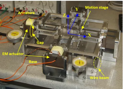
a. The spatial multi-beam module may act as an indepen-dent motion stage actuated by the non-contact electro-magnetic (EM) actuators (an example desktop-size XY compliant parallel manipulator is shown in Fig. 1). This motion stage has a very simple configuration and large out-of-plane stiffness, and has no the heat effect from the EM actuator due to the non-contact actuation. Due
to the fact that the output motion stage acts as the input stage as well, no lost motion exists and fewer sensors are needed.
b. A spatial multi-beam module can also be used as the ba-sic building block of new multi-axis compliant parallel manipulators, for example as a spatial leg to enhance the out-of-plane stiffness of an XY compliant parallel ma-nipulator (Hao and Kong, 2012a), and as a passive PPR (P: prismatic joint, R: revolute joint) joint of an XYZ compliant parallel manipulator (Hao and Kong, 2012b) (Fig. 2).
Figure 1.A desktop-size XY compliant parallel manipulator ac-tuated by two EM actuators (where the twisting rotation about the
z axis is well constrained by appropriately setting up the ratio of
the motion stage size to the wire beam length and making beams distribute around multiple circles).
Over the past decade, PRBMs (pseudo-rigid-body models) (Howell et al., 1996; Howell, 2001; Su, 2009; Ramirez and Lusk, 2011) have drawn plenty of attentions due to dramati-cally simplifying the design and analysis of compliant mech-anisms using the knowledge body of rigid-body mechmech-anisms with springs. In PRBM, the compliant beams are typically re-placed with the pseudo-rigid-body link(s) coupling with one or more characteristic pivots with specified spring stiffness located at specified position(s). Most researches have been conducted for proposing PRBMs of planar-motion compliant mechanisms with planar-motion members such as the fixed-free beam, fixed-guided beam, parallelogram mechanism, cartwheel rotational joint and fixed-clamped carbon nan-otubes (Howell et al., 1996, 2010; Howell, 2001; Su, 2009), which has resulted in very accurate approximation of load-displacement relationships. However, less work has been re-ported for PRBMs of spatial-motion compliant beams such as spatial-motion axisymmetric cantilever beams (Ramirez and Lusk, 2011).
This paper aims to propose a simplified PRBM of the spa-tial multi-beam module over intermediate range of motion (transverse bending displacement up to 10 % of beam length) for the above two types of applications/loading conditions where the planar twisting DOF (degree of freedom) is con-strained (very small) and only the two primary translations are left as the DOF. The present PRBM is envisaged to re-flect the primary nonlinear constraint characteristics, which can detect the performance merits and shortcomings to en-able the quick design synthesis.
The rest sections of this article are organized as follows. Section 2 derives the simplified PRBMs of spatial multi-beam modules. In Sect. 3, FEA results are illustrated to verify the PRBM of the spatial three-beam module. Some
improve-sions are drawn.
2 Simplified PRBMs of spatial multi-beam modules
2.1 Simplified PRBM for a fixed-fixed beam in planar motion
The simplified PRBM of a fixed-fixed beam with a length of L in planar motion has been suggested by the previous work (Howell, 2001) where two rotational joints with each rota-tional spring stiffness Kbare each located the same distance
from their respective end and the rigid-body link has a length ofγL. These arguments may provide a strong reference for the PRBM of the fixed-fixed beam in spatial motion in a straightforward way. The bending stiffness, Kb=2γKθEI/L
(Kθ, bending stiffness coefficient, E, Young’s Modulus, and I, second moment of cross-section area), and the character-istic factor,γ, can be obtained from the analytical nonlinear model of a parallelogram flexure module composed of two fixed-fixed leaf beams (Awtar and Slocum, 2007) as derived below.
The virtual work principle (Howell, 2001) for the parallel-ogram flexure module yields
FydYs+PdXs=
∂U ∂Ys
dYs (1)
where the variable Ysis the generalized coordinate that is the
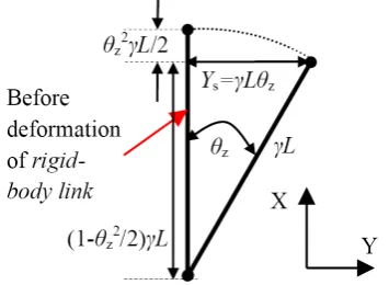
primary translational displacement of the motion stage center along the y axis. Xs=−[1−cos(γYLs)]γL=−(
Ys
γL)
2γL/2, which
is the parasitic translational displacement of the motion stage along the x axis (see Fig. 3 for the details). Fyand P are the
transverse force and the axial force along the y and x axes, respectively, and U is the total elastic energy from the defor-mation contribution of four rotational joints, which is equal to 4×0.5Kb(γYLs)2. Here, γYLs is used to denote the rotational
displacement,θz, of each rotational joint.
Differentiating Eq. (1) with respect to Ysproduces
Fy−Pd[(γYLs)2γL/2]/dYs= d[4×1
2Kb(YsγL)
2]
dYs
⇒
Ys=
Fy
4Kb/(γL)2+P/(γL)
(2)
In addition, the closed-form analytical solution for the pri-mary translational displacement of the parallelogram flexure module is shown below (Awtar and Slocum, 2007):
Ys =
Fy/(EI/L2)
2a+Pe/(EI/L2)L=
Fy
2a(EI/L3)+Pe/L
= Fy
24(EI/L3)+1.2P/L (3)
Comparing Eq. (2) and Eq. (3), we can observe that
(
1/γ=1.2⇒γ=0.833
Kb/γ2=6(EI/L)⇒Kb=4.167EI/L
Figure 2.A compact and decoupled XYZ compliant parallel manipulator composed of identical spatial four-beam modules: (a) 3-PPPR XYZ CPM, and (b) corresponding monolithic design to be fabricated from a cubic material by three orthogonal directions’ cutting.
Figure 3.Kinematics schematic diagram of bending about z axis of a fixed-fixed beam.
It is noted that, during the above derivation, the characteris-tic factor,γ, is independent of the cross-section shape or the second moment of cross-section area, I. From Eq. (4), it can be observed the bending stiffness coefficient Kθ=2.50.
2.2 Simplified PRBMs for spatial multi-beam modules The spatial deformation/motion of a fixed-fixed beam within a spatial three-beam module (Fig. 4) can be stimulated via the superposition principle using the results from the inde-pendent two planar bending motions (Sect. 2.1) along with the twisting motion. The spatial-motion beam can be accord-ingly equivalent to a rigid-body link with two identical spher-ical joints (Wang et al., 2008; Ramirez and Lusk, 2011). Sim-ilarly, each spherical joint is located each located the same distance from their respective end and the rigid-body link has a length ofγL (γ=0.833). For each spherical joint, the twisting stiffness Ktcan be simply derived as Kt=2GIp/L=
4GI/L(Ip=2I), and the bending stiffness Kbabout any
bend-ing axis is obtained as Kb=2γKθEI/L=4.167EI/L based
on the result derived in Sect. 2.1 (Eq. 4).
According to the virtual work principle and under the as-sumption of negligible bending rotation (which implies the twisting rotation is very small), we obtain the following ex-pression for the spatial three-beam module (Fig. 4):
FydYs+FzdZs+PdXs+Mxdθsx
=∂∂U Ys
dYs+
∂U ∂Zs
dZs+
∂U ∂θsx
dθsx (5)
where the variables Ys, Zsandθsxare the generalized
coordi-nates along the y, z, and x axes, respectively, which are the primary motion displacements of the motion stage center, O’, with regard to the fixed coordinate system O-XYZ. Xsis the
parasitic translation along the x axis. Fy, Fz and P are the
two transverse forces and the axial force along the y, z, and x axes, respectively, and Mxis the twisting moment about the
x axis. U is the total elastic energy.
As shown in Fig. 4, there are six spherical joints for the spatial three-beam module in its PRBM embodiment. Based on the small range of motion assumption and superposition principle, we have
U = 6×1
2Kb Ys
γL !2
+6×1
2Kb
Zs
(1−(Ys/γL)2/2)γL
!2
+ 6×1
2Kt θ
sx
2 2
+6×1
2Kb R3θsx
γL !2
(6)
Xs = −
"
1−cos Ys γL
!# γL−
"
1−cos Zs γL
!# γL
−
"
1−cos R3θsx γL
!#
γL=− Ys
γL !2
γL/2
− Zs
γL !2
γL/2− R3θsx
γL !2
Figure 4.Spatial three-beam module and the corresponding PRBM.
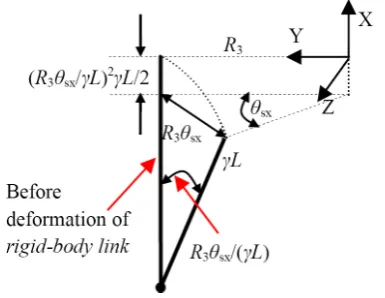
Figure 5.Kinematic schematic diagram of twisting rotation about the x axis of the spatial three-beam module.
where the kinematic relationships used for bending and twist-ing are shown in Figs. 3 and 5. Moreover, the bendtwist-ing in the XOY plane is assumed to be the first rotation about the z axis, and that in the XOZ plane is assumed to be the second rota-tion about the y axis. Therefore, Ys
γL and Zs
(1−(Ys/γL)2/2)γL are
used herein to denote the rotational angles about the y and z axes, respectively, in order to capture the tiny cross-axis coupling in the two primary translational directions.
Substituting Eqs. (6) and (7) into Eq. (5), we obtain
Fy−Pd
Ys γL !2
γL/2 /dYs=
d 3Kb Y s γL 2 dYs + d " 3Kb Zs
(1−(Ys/γL)2/2)γL
2#
dYs =
6KbYs
(γL)2
+6KbYs
(γL)2
Zs2/(γL)2
[1−(Ys/γL)2/2]3
≈6KbYs
(γL)2 +
6KbYs
(γL)2Z 2 s/(γL)
2
=6KbYs
(γL)2[1+Z 2 s/(γL)
2] (8)
⇒
Ys≈
Fy
6Kb[1+Zs2/(γL)2]/(γL)2+P/(γL)
= Fy
6Kb
1+ Fz
6Kb/(γL)2+P/(γL)
2
/(γL)2/(γL)2+P/(γL)
Fz−Pd
Zs γL !2
γL/2 /dZs=
d
3Kb
Zs
(1−(Ys/γL)2/2)γL
2
dZs
=6KbZs
(γL)2
1 [1−(Ys/γL)2/2]2
≈6KbZs
(γL)2
1 1−(Ys/γL)2
=6KbZs
(γL)2
1+(Ys/γL)2
1−(Ys/γL)4
≈6KbZs
(γL)2[1+Y 2 s/(γL)
2] (9)
⇒
Zs=
Fz
6Kb[1+Ys2/(γL)2]/(γL)2+P/(γL)
= Fy
6Kb
1+ Fy
6Kb/(γL)2+P/(γL)
2
/(γL)2/(γL)2+P/(γL)
Mx−Pd
R3θsx
γL !2
γL/2
/dθsx
= d
3Ktθ2sx/4+3Kb
R3θsx
γL
2
dθsx
(10)
⇒
θsx=
Mx
1.5Kt+6KbR23/(γL)2+PR 2 3/(γL)
X1=Xs−
√
3R3θsz/2+R3θsy/2 (11)
X2=Xs−R3θsy (12)
X3=Xs+
√
3R3θsz/2+R3θsy/2 (13)
Y1=Ys−R3θsx/2 (14)
Y2=Ys+R3θsx (15)
Y3=Ys−R3θsx/2 (16)
Z1=Zs+
√
3R3θsx/2 (17)
Z2=Zs (18)
Z3=Zs−
√
3R3θsx/2 (19)
where Xi, Yiand Ziare the translational displacements for the i-th beam tip along the x, y, and z axes.
Based on Figs. 3 and 5, we have the translational displace-ment along the x axis for each beam tip:
Xi=− Yi
γL !2
γL/2− Zi
γL !2
γL/2=− Y
2
i
2γL− Zi2
2γL (20)
Using Eqs. (11), (12) and (13), we can obtain the two bending rotaions about the y and z axes with eliminating the motion stage center displacement, Xs, along the x axis as:
θsy=
(X1+X3)−2X2
3R3
(21)
θsz=
X3−X1
√
3R3
(22)
Substituting Eq. (20) into Eq. (21), and then substituting Eqs. (14)–(19) to the result, we have
θsy=θsxYs/(γL) (23)
Similarly, substituting Eq. (20) into Eq. (22), and then sub-stituting Eqs. (14), (16), (17) and (19) to the result, we have
θsz=θsxZs/(γL) (24)
Analogously, the PRBMs of a class of spatial multi-beam modules that all the beams thereof are uniformly spaced around a circle with a radius of Rn (n> =3 and is even for n,3) can be derived as following:
Ys=
Fy
2nKb[1+Zs2/(γL)2]/(γL)2+P/(γL)
(25)
Zs=
Fz
2nKb[1+Ys2/(γL)2]/(γL)2+P/(γL)
(26)
θsx=
Mx
nKt/2+2nKbR2n/(γL)2+PR2n/(γL)
(27)
Xs=−
Ys
γL !2
γL/2− Zs
γL !2
γL/2− Rnθsx
γL !2
γL/2 (28)
θsy=θsxYs/(γL) (29)
θsz=θsxZs/(γL) (30)
where the loading and displacements are defined in a similar way as mentioned above. The axial force in the denominator terms of Eqs. (25), (26) and (27) causes the load-stiffening effect. When the primary translation stiffness and the twist-ing stiffness are zero, two values of the axial force P are ob-tained. The minimal absolute value of the axis force is the buckling load, which is equal to 10nEI/L2. In addition, the
cross-axis coupling is captured for the two primary transla-tional directions.
Note that Eq. (27) can still be used to estimate the large twisting rotation under the action of the dominant twisting moment only although the twisting rotation is assumed to be very small during the above derivation.
When translational displacements and length parameters are normalized by the beam length L, forces by EI/L2, mo-ments by EI/L, and all normalized results are denoted by their lower-case letters, Eqs. (25)–(30) can be re-written as
ys≈
fy
12n(1+1.44z2 s)+1.2p
zs≈
fz
12n(1+1.44y2 s)+1.2p
θsx≈n(2G/E+12rmx2
n+1.2pr2n/n) xs≈ −0.6(y2s+z2s+rn2θ2sx)
θsy=1.2θsxys
θsz=1.2θsxzs
(31)
Comparing Eq. (30) with the previously reported analytical work (Hao et al., 2011), we can see that the present PRBMs are well coincident with the dominant terms of the associated nonlinear analytical results.
For a spatial multi-beam module as applied in Figs. 1 and 2, its twisting rotation can be negligible. Equations (25), (26) and (28) are therefore capable of determining the three trans-lational displacements for a general spatial module with total n beams no matter how these beams are distributed.
3 FEA result comparisons
In order to verify the accuracy of the present PRBMs of spatial multi-beams, an example spatial three-beam module (Fig. 4) is analyzed using nonlinear FEA software (Com-sol). The spatial three-beam module is taken to be made from a standard aluminium alloy for which Young’s mod-ulus, E, is 69 000 N mm−2and Poisson’s ratio, v, is 0.33. The beam has round cross-section with a diameter of D=4 mm. The other geometrical parameters are set as R3=30 mm and
Figure 6.Parasitic translational displacement verification.
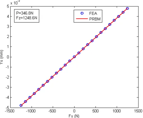
Figure 7.Primary translational displacement verification: primary stiffness.
FEA results with comparisons with the PRBM results for the spatial three-beam module are shown in Figs. 6–11. It is shown in Figs. 6, 7, 8 that the translational displace-ments, including the primary motion and parasitic motion, obtained from the FEA have a good agreement with those obtained from the PRBM. The maximal differences in per-centage (FEA results as the denominator) in Figs. 6, 7, 8 are 2.18 %, 0.40 % and 0.43 %, respectively.
The FEA results and the PRBM results both capture the cross-axis coupling effect in the two primary translational directions with an acceptable difference (Fig. 9), which de-scribes that the cross-axis force slightly increases the primary translational stiffness. The maximal cross-axis coupling er-ror from the FEA is of 0.83 %, and that from the PRBM is 1.24 %, which suggests that the cross-axis coupling in two primary translational directions can be ignored.
Figure 8.Primary translational displacement verification: cross-axis coupling effect caused by the axial force.
Figure 9.Primary translational displacement verification: cross-axis coupling effect in the two primary translational directions.
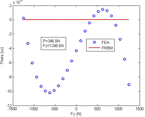
Figure 10 shows that the twisting angle about the X-axis obtained from the FEA results is within 10µrad (most prob-ably from the inaccuracy of the FEA results) compared with the zero value obtained from the PRBM results when only pure forces are exerted on the motion stage center.
In addition, the FEA results capture the bending rotation, θsz, under the dominant force, Fy, with the value less than
1.5 mrad (Fig. 11), which is not obtained by the PRBM re-sults (Eq. 30). From the analytical rere-sults in Hao et al. (2011), the bending rotation effect can be smaller when R3increases
and/or D decreases. The dominant kinematic effect compo-nent of the bending angle (θsz) caused by the non-dominant
coupled loads (Mx and Fz) (Eq. 30) has been roughly
Figure 10.Twisting angle about the x axis.
4 Discussions
As shown in PRBMs proposed in this paper and/or Figs. 6 and 11, the purely elastic effect of the axis force along the x axis and the parasitic bending rotation caused by the domi-nant force (or moment) are lost, which is the main shortcom-ing of the PRBMs. One alternative approach to overcome this issue is to use the PRBMs for determining the two pri-mary translational motions and to use the analytical results in Hao et al. (2011) for capturing the other characteristics. The PRBMs of spatial multi-beam modules may be re-derived via using three spherical joints in each leg similar to the planar motion case reported in Su (2009).
In addition, the PRBM for a fixed-fixed beam in spatial motion can be modified via the use of the recently developed results to capture the coupling between the two bending di-rections in the presence of a torsional load (Sen and Awtar, 2013), and/or the kinematic and elastokinematic components of twisting angle in the presence of bending displacements (Hao et al., 2011; Sen and Awtar, 2013).
5 Conclusions
Simplified PRBMs have been presented in this paper to deal with the spatial multi-beam modules with planar motion for specific applications/loading conditions via replacing each beam with a rigid-body link plus two identical spherical joints. The characteristics factor, bending stiffness and twist-ing stiffness for the spherical joint have been determined. These presented load-displacement equations have been ver-ified by nonlinear FEA software, which can be used to pre-dict the nonlinear characteristics such as load-stiffening ef-fect, cross-axis coupling in the two primary translational di-rections and buckling load.
Figure 11.Bending angle about the z axis.
It is noted that the PRBM proposed in this paper can be further improved to capture the additional nonlinear charac-teristics such as the purely elastic effect of axis force along the x axis, and the bending rotation caused by the dominant load. The PRBMs for more generality with diverse loading conditions also deserve the future investigations.
Acknowledgements. The author would like to thank final year undergraduates John Mullins and Mark Bruton in UCC for their contribution to Fig. 1.
Edited by: H. Su
Reviewed by: C. Lusk and one anonymous referee
References
Awtar, S. and Slocum, A. H.: Characteristics of Beam-Based Flex-ure Modules, J. Mech. Design, 129, 624–639, 2007.
Culpepper, M., DiBiasio, C., Panas, R., Magleby, S., and Howell, L. L.: Simulation of a Carbon Nanotube-Based Compliant Parallel-Guiding Mechanism: A Nanomechanical Building Block, Appl. Phys. Lett., 89, 203111, doi:10.1063/1.2388143, 2006.
Hao, G. and Kong, X.: Novel XY Compliant Parallel Manipulators for Large Translation with Enhanced Out-of-Plane Stiffness, J. Mech. Design, 134, 061009, doi:10.1115/1.4006653, 2012a. Hao, G. and Kong, X.: Design and Modelling of a Large-Range
Modular XYZ Compliant Parallel Manipulators Using Identi-cal Spatial Modules, Journal of Mechanisms and Robotics, 4, 021009, doi:10.1115/1.4006188, 2012b.
Hao, G., Kong, X., and Reuben, R. L.: A Nonlinear Analysis of Spa-tial Compliant Parallel Modules: Multi-beam Modules, Mech. Mach. Theory, 46, 680–706, 2011.
Howell, L. L.: Compliant Mechanisms, Wiley, New York, 2001. Howell, L. L., Midha A., and Norton, T. W.: Evaluation of
126–131, 1996.
Howell, L. L., DiBiasio, C. M., Cullinan, M. A., Panas, R., and Culpepper, M. L: A Pseudo-Rigid-Body Model for Large De-flections of Fixed-Clamped Carbon Nanotubes, Journal of Mech-anisms and Robotics, 2, 034501-1–034501-5, 2010.
Ramirez, I. A. and Lusk, C. P.: Spatial-Beam Large-Deflection Equations and Pseudo-Rigid Body Model for Axisymmetric Cantilever Beams, Proceedings of the ASME 2011 International Design Engineering Technical Conferences & Computers and In-formation in Engineering Conference, IDETC/CIE 2011, 29–31 August 2011, Washington, DC, USA, DETC2011-47389, 2011.
straint Characteristics of Symmetric Spatial Beams, J. Mech. De-sign, 135, 031003, doi:10.1115/1.4023157, 2013.
Su, H.-J.: A Pseudo-Rigid-Body 3R Model for Determining Large Deflection of Cantilever Beams Subject to Tip Loads, Journal of Mechanisms and Robotics, 1, 021008, doi:10.1115/1.3046148, 2009.