R E S E A R C H
Open Access
Mechanical strength of a new plate
compared to six previously tested opening
wedge high tibial osteotomy implants
Arnaud Diffo Kaze
1,2,3*, Stefan Maas
1,3, James Belsey
4, Alexander Hoffmann
2,3,5, Romain Seil
2,3,5,
Ronald van Heerwaarden
6and Dietrich Pape
2,3,5Abstract
Background:This study aimed to assess the mechanical static and fatigue strength provided by the FlexitSystem
plate in medial opening wedge high tibial osteotomies (MOWHTO), and to compare it to six previously tested implants: the TomoFix small stature, the TomoFix standard, the ContourLock, the iBalance, the second generation PEEKPower and the size 2 Activmotion. Thus, this will provide surgeons with data that will help in the choice of the most appropriate implant for MOWHTO.
Methods:Six fourth-generation tibial bone composites underwent a MOWHTO and each was fixed using six
FlexitSystem plates, according to standard techniques. The same testing procedure that has already been previously defined, used and published, was used to investigate the static and dynamic strength of the prepared bone-implant constructs. The test consisted of static loading and cyclical loading for fatigue testing.
Results:During static testing, the group constituted by the FlexitSystem showed a fracture load higher than the physiological loading of slow walking (3.7 kN > 2.4 kN). Although this fracture load was relatively small compared to the average values for the other Implants from our previous studies, except for the TomoFix small stature and the Contour Lock. During fatigue testing, FlexitSystem group showed the smallest stiffness and higher lifespan than the TomoFix and the PEEKPower groups.
Conclusions:The FlexitSystem plate showed sufficient strength for static loading, and average fatigue strength compared to the previously tested implants. Full body dynamic loading of the tibia after MOWHTO with the investigated implants should be avoided for at least 3 weeks. Implants with a wider T-shaped proximal end, positioned onto the antero-medial side of the tibia head, or inserted in the osteotomy opening in a closed-wedge construction, provided higher mechanical strength than implants with small a T-shaped proximal end, centred onto the medial side of the tibia head.
Keywords:High tibial osteotomy (HTO), Osteoarthritis, FlexitSystem, Activmotion, TomoFix, PEEKPower,
ContourLock, iBalance, Permanent deformation, Correction angle, Biomechanics, Mechanical stiffness, Static strength, Fatigue strength
© The Author(s). 2019Open AccessThis article is distributed under the terms of the Creative Commons Attribution 4.0 International License (http://creativecommons.org/licenses/by/4.0/), which permits unrestricted use, distribution, and reproduction in any medium, provided you give appropriate credit to the original author(s) and the source, provide a link to the Creative Commons license, and indicate if changes were made.
* Correspondence:[email protected]
1Faculty of Science, Technology and Communication, University of
Luxembourg, 6, rue R. Coudenhove-Kalergi, L-1359 Luxembourg, Luxembourg
2Department of Orthopedic Surgery, Centre Hospitalier de Luxembourg,
L-1460 Luxembourg, Luxembourg
Background
Medial open-wedge high tibial osteotomy (MOWHTO) is a common intervention used for the treatment of medial compartment gonarthrosis with varus malalign-ment in young and active patients (Amendola and Bona-sia2010; Pape et al. 2004). The maintenance of primary stability after MOWHTO depends on factors associated with the surgical technique and the implants used (Brinkman et al. 2008; Lobenhoffer and Agneskirchner
2003; Spahn et al. 2006; Spahn et al.2007). Precise pre-operative planning and high primary fixation stability of the implant are required for a good outcome (Pape et al.
2004). Numerous implants for MOWHTO are available on the market, which have different shapes and varying biomechanical and material properties. It is important to quantify and compare the stabilising effect of these im-plants to assist surgeons in the choosing of the most ap-propriate implant from a mechanical point of view. Diffo Kaze et al. performed biomechanical studies (Maas et al.
2013; Diffo Kaze et al.2015; Diffo Kaze2016; Diffo Kaze et al. 2017) that compared the following six implants: the TomoFix small stature (TomoFix sm) and TomoFix standard (TomoFix std) plates of Synthes Gmbh (Oberdorf, Switzerland), and the ContourLock plate, the iBalance implant and the second generation PEEKPower plate of Arthrex (Munich, Germany), and the size 2 Activmotion plate of Newclip Technics (Haute-Goulaine, France) (Tables1and2, groups I to VI). The FlexitSystem of Neosteo (Nantes, France) is a new HTO implant (Table2, Group VII) that is pre-contoured to fit the medial proximal tibia, similar to the other five previously tested plates. The iBalance implant is inserted centrally into the osteotomy gap on the medial side of the tibia head. Except for the size 2 Activmotion, which is positioned onto the antero-medial surface of the tibia head, all the previously tested implants and the FlexitSystem have their proximal part centred onto the medial surface of the tibia head. The proximal part of the FlexitSystem is dimensionally comparable to the other T-shaped implants, but has only three proximal screws whereas the others have four.
In the present study, we aimed to compare the mech-anical static and fatigue strength provided by the FlexitSystem against the six previously tested implants designed for the treatment of medial knee joint osteo-arthritis, using a testing procedure that has already been defined, used and published (Maas et al. 2013; Diffo Kaze et al. 2015; Diffo Kaze 2016; Diffo Kaze et al.
2017). We hypothesized the following: (1) The bone-implant constructs with the FlexitSystem should fail due to the collapse of the opposite cortex. (2) Due to its similar positioning and T-shaped form as the TomoFix and the PEEKPower plates, but with only three proximal screws, the FlexitSytem should provide comparable or lower mechanical strength than the TomoFix and the
PEEKPower plates. (3) This means that the FlexitSystem should be inferior to the iBalance, the Activmotion and the Contour Lock, based on the observations of the pre-vious studies regarding the mechanical stability provided by implants (Maas et al. 2013; Diffo Kaze et al. 2015; Diffo Kaze2016; Diffo Kaze et al.2017).
Methods
MOWHTO with FlexitSystem plates were performed on six large-size fourth generation composite analogue tibia bone models (Sawbones, Pacific Research Laboratories, Inc., Vashon, WA) in the same way by an experienced surgeon, according to standard techniques of the plate. The same standardised procedure, as used in the previ-ously performed osteotomy tests (Maas et al.2013; Diffo Kaze et al. 2015; Diffo Kaze 2016; Diffo Kaze et al.
2017), was used to prepare the specimens. The same loading protocols for static and dynamic tests, as for our previous studies, were employed to test the FlexitSystem specimens. Hence, the FlexitSystem (Table 2, Group VII) was able to be compared to the six previously tested implants (Tables 1 and 2; Group I to VI). Overall, the thirty-three specimens, whose test results were used in the present study, were subdivided according to the type of test performed, as indicated in Table 3. It has been shown that the loading of the specimens that was used for the experimental setup, corresponded to a realistic loading of the lower limb during the loading response phase of slow walking (Diffo Kaze et al.2018).
For the static tests, the specimens were subjected to a quasi-static compression,displacement-controlled single loading to failure at a speed of 0.1 mm/s. The dynamic tests consisted of load-controlled cyclical fatigue testing, with stepwise compression and sinusoidal (frequency = 5 Hz) loading, where the force amplitude of each step was kept constant by the feedback control of the force signal within the hydraulic machine. The lower compressive force limit of each load step was kept constant at 160 N. Starting at 800 N for the first step, the upper compres-sive force limit was increased stepwise by 160 N after
N= 20,000 cycles if no failure occurred.
embedded in the INSTRON machine measured the ver-tical displacement of piston (Fig.1-B).
Failure criteria
The following failure criteria (Table 4) that have already been used by Pape et al. (Pape et al.2010) and consid-ered in the previous studies were considconsid-ered in the present study. The failure type 3 allow for a quantifying of the wobble degree, or stability, of the sample during the cyclic testing (Maas et al. 2013; Diffo Kaze et al.
2015; Diffo Kaze2016; Diffo Kaze et al.2017).
Permanent deformation and deflection due to plastic deformation during the cyclic testing
The permanent deformation, after unloading the speci-men, results from plastic deformation. It was estimated as the irrecoverable displacement from the start of the tests at the minimal force of 160 N that was considered as nearly zero force. The permanent deflection angleαpafter
the collapse of the contralateral cortex during the cyclic tests was determined using the method indicated by Diffo Kaze et al. (Diffo Kaze et al.2015; Diffo Kaze2016; Diffo Kaze et al. 2017). The deflection angle corresponds to a rotation of the tibia head relative to the shaft, which
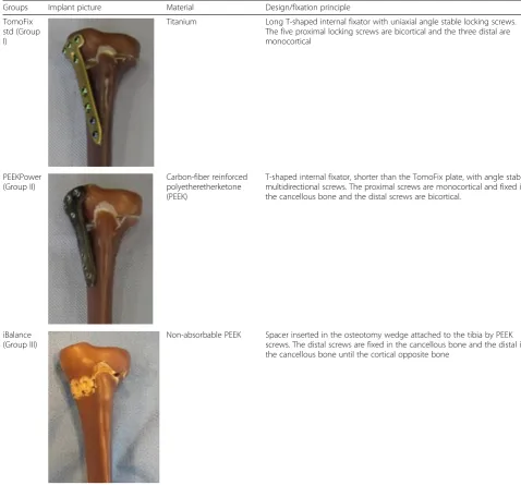
Table 1Different HTO implants considered in the study (Groups I, II and III)
Groups Implant picture Material Design/fixation principle
TomoFix std (Group I)
Titanium Long T-shaped internal fixator with uniaxial angle stable locking screws. The five proximal locking screws are bicortical and the three distal are monocortical
PEEKPower (Group II)
Carbon-fiber reinforced polyetheretherketone (PEEK)
T-shaped internal fixator, shorter than the TomoFix plate, with angle stable multidirectional screws. The proximal screws are monocortical and fixed in the cancellous bone and the distal screws are bicortical.
iBalance (Group III)
Non-absorbable PEEK Spacer inserted in the osteotomy wedge attached to the tibia by PEEK screws. The distal screws are fixed in the cancellous bone and the distal in the cancellous bone until the cortical opposite bone
occurs in the frontal plane (Fig.2). It was calculated as the deflection resulting from the absolute difference between the lateral and medial displacements. Permanent deflec-tion angle αp, greater than 0.024 rad or 1.4°, corresponds
to the occurrence of failure type 1 (Table4).
Stiffness of the specimens
The dynamic stiffness of the specimens was determined as the damage indicator during the cyclic tests. It was
calculated as the ratio of peak to peak forceΔF to the mea-sured peak to peak displacementΔX in the same period
K¼ ΔF ΔX:
The static stiffness, at the critical state when the dam-age of the specimen occurs, was calculated as the ratio of the corresponding damage load (FDamage) to the
corre-sponding displacement (XDamage)
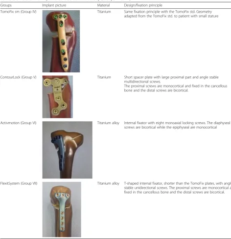
Table 2Different HTO implants considered in the study (Groups IV to VII)
Groups Implant picture Material Design/fixation principle
TomoFix sm (Group IV) Titanium Same fixation principle with the TomoFix std. Geometry adapted from the TomoFix std. to patient with small stature
ContourLock (Group V) Titanium Short spacer plate with large proximal part and angle stable multidirectional screws.
The proximal screws are monocortical and fixed in the cancellous bone and the distal screws are bicortical.
Activmotion (Group VI) Titanium alloy Internal fixator with eight monoaxial locking screws. The diaphyseal screws are bicortical while the epiphyseal are monocortical
FlexitSystem (Group VII) Titanium alloy T-shaped internal fixator, shorter than the TomoFix plates, with angle stable unidirectional screws. The proximal screws are monocortical and fixed in the cancellous bone and the distal screws are bicortical.
K¼ FDamage XDamage:
Statistical analysis
The number of specimens was limited due to financial reasons. There were neither final loads, displacements of the tibia head, nor number of cycles prior to failure that
were predefined as reference quantities in the present study. Hence, no statistical analyses were performed within each group. The t-test for two independent sam-ples was used to compare the ultimate loads, the dis-placements of the tibia head, the valgus malrotation, the lateral stiffness and the number of cycles prior to failure between the FlexitSystem group and the others. Statis-tical analysis was performed using Microsoft Excel 2010
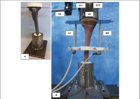
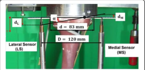
Fig. 1Specimen and sensors’locations:aSpecimen before mounting to hydraulic press.bSpecimen under test. The lateral and the medial sensor (LS and MS) register the relative lateral and medial vertical displacements from the tibial head, while VS measured its vertical displacement. The sensors DX, DY1 and DY2 register the horizontal displacements of the tibial head; along the transverse axis for the first and the sagittal axis for the latter
Table 3Specimen grouping and assignment, depending on used implants and the performed test
Performed test Group I;
n= 5 Specimens
Group II; n= 5 Specimens
Group III; n= 6 Specimens
Group IV; n = 5 Specimens
Group V; n= 5 Specimens
Group VI; n= 6 Specimens
Group VII; n= 6 Specimens
Static: single loading to failure test TomoFix 1 PEEKPower 1 iBalance 1 TomoFix sm 1 Contour Lock 1 Activmotion 1 FlexitSystem 1
TomoFix 2 PEEKPower 2 iBalance 2 TomoFix sm 2 Contour Lock 2 Activmotion 2 FlexitSystem 2
Dynamic: cyclic fatigue to failure test TomoFix 3 PEEKPower 3 iBalance 3 TomoFix sm 3 Contour Lock 3 Activmotion 3 FlexitSystem 3
TomoFix 4 PEEKPower 4 iBalance 4 TomoFix sm 4 Contour Lock 4 Activmotion 4 FlexitSystem 4
TomoFix 5 PEEKPower 5 iBalance 5 TomoFix sm 5 Contour Lock 5 Activmotion 5 FlexitSystem 5
software (Microsoft Corporation, Redmond, Washing-ton, USA). All statistical tests were performed two sided. Statistical significance was considered atp< 0.05.
Results
The same materials and methods from our previously performed and published studies were used for the spec-imens with the FlexitSystem plate (Group VII, Table 2) in the present study. Hence, the results obtained from all these studies were comparable. The published results of our previous studies (Groups I to VI, Table2) are also presented here for comparison purposes.
Static loading to failure
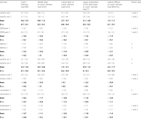
During the static testing, the FlexitSystem specimens failed by fracture of the contralateral cortex (Fig.2), simi-lar to all the previously tested specimens. The fractures were abrupt and no crack formation prior to the ultimate rupture was observed. No defects of the plates or screws were observed.
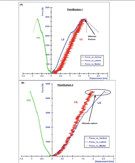
The lateral side of the tibia head performed a down-ward movement, which was considered as positive, while the medial side performed an upward movement, which was considered negative. Thus, the medial displacements
(MS) were negative and the lateral displacements were positive (Fig. 3). Consequently, a rotation of the tibia plateau in the frontal plane, valgus-malrotation, was ob-served. The lateral displacements had larger absolute amplitude than the medial displacements (Fig.4).
For the FlexitSystem 1, the ultimate load was approxi-mately 2.9 kN, which corresponded to medial and lateral displacements of about 1 mm and 2.5 mm respectively. For the FlexitSystem 2 the ultimate load was approxi-mately 4.5 kN, which corresponded to an ultimate med-ial displacement of 1.15 mm and a lateral displacement of 2.7 mm (Fig.4).
The results of the static tests performed on the Flexit-System were summarised together with the results of our previous studies (Table 5) and have been reported here for comparison purpose.
Overall, the highest average ultimate load, the point at which the specimens collapsed during the single loading to failure test, was 8.2 kN and occurred in group 6 (Activmotion). The Contour Lock 1 and 2 specimens showed the largest average lateral displacement (4.1 mm) at fracture of the lateral cortex. The iBalance group showed the highest lateral stiffness at ultimate load (3.1 kN/mm).
Fig. 2Fracture of the lateral cortex during static testing (FlexitSystem 1). The opposite cortex appeared to be the weak point of the bone-implant constructs
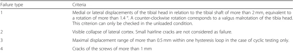
Table 4Used failure types and their defining criteria (Maas et al.2013; Diffo Kaze et al.2015; Diffo Kaze2016; Diffo Kaze et al.2017)
Failure type Criteria
1 Medial or lateral displacements of the tibial head in relation to the tibial shaft of more than 2 mm, equivalent to a rotation of more than 1.4 °. A counter-clockwise rotation corresponds to a valgus malrotation of the tibia head. This criterion can only be checked in the unloaded condition.
2 Visible collapse of lateral cortex. Small hairline cracks are not considered as failure.
3 Maximal displacement range of more than 0.5 mm within one hysteresis loop in the case of cyclic testing only.
For all implant types, the average displacement on the medial side compared to the lateral side was always smaller. The determined valgus-malrotation of the tibia head was greater than, or equal to, the fixed limit of 1.4° of the per-manent deflection angle for all implants with the exception of the iBalance and Activmotion specimens, which showed mean values 0.9 ° and 1° respectively. The TomoFix std. group showed the maximal valgus-malrotation at collapse time of the contralateral cortex (2.8 °).
The differences that were observed between the FlexitSystem group and the other groups, regarding the investigated parameters, were in majority statistically non-significant. The differences in the cases of valgus-malrotation and lateral displacement were statistically significant compared to the TomoFix std. and the Con-tour Lock, respectively (Table6).
Fatigue loading to failure
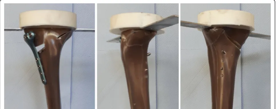
The fracture of the FlexitSystem specimens subjected to cyclical tests occurred at the lateral cortex (Fig. 5), as with the static tests. If cracks occurred prior to the final failure of the specimens, they were generally not observ-able. The plates and screws remained undamaged during the cyclical testing. The tibia head of the specimens ro-tated counterclockwise, indicating a valgus-malrotation, which was also observed during the static tests.
A type 3 failure, which was checked by means of the maximal displacement range within hysteresis loops, did not occur in the FlexitSystem group, as well as in groups I, II,III and VI. This failure type occurred only in the Tomo-Fix sm and Contour Lock groups (Diffo Kaze et al.2017).
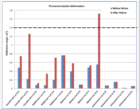
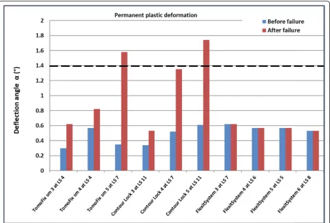
Figure 6 shows the values of the permanent plastic valgus-malrotation for groups I, II,III and VI from our pre-vious study (Diffo Kaze et al.2017). Figure7shows the per-manent plastic deflection angle in groups IV, V and VI. The load history was indicated with the Load Step number (LSn) at which the failure occurred. A permanent plastic deflection angle after the failure was not determined in the
FlexitSystem group, as the test was stopped immediately as the failure occurred. Therefore, the value after the failure was assumed to be equal to the value that was obtained be-fore the failure. A type 1 failure, which was characterised by a permanent plastic deflection angle greater than 1.4 °, oc-curred only in the iBalance, TomoFix sm and Countour Lock groups, but after the failure of the specimen.
The deflection angles prior to the gross failure in the FlexitSystem group were, on average, higher than in the other groups.
For the sake of comparison, the results of the fatigue tests from our previous studies were summarised, together with the results that were obtained from the testing on the FlexitSystem plate (Table7). This summary lists the max-imal compressive force, the lateral and vertical stiffness of the specimens at the beginning of the first load step, the minimal number of cycles performed prior to the failure, and the types of failure. Average values and standard devi-ations in each group are given in Table8.
For groups I, II, VI and VII only a type 2 failure was observed (Table 7). A damage of the fixation system oc-curred in the iBalance group. The FlexitSystem group showed the smallest stiffness values. The Contour Lock showed the highest average maximal load and number of cycles prior to failure.
Regarding the parameters investigated for the fatigue loading to failure tests, the Contour Lock group showed the highest values followed by the Activmotion group. The highest lateral and medial stiffness was observed in the Activmotion and iBalance groups respectively. The PEEKPower group showed higher stiffnesses than the TomoFix plates.
For better comparison with the TomoFix std., which is the gold standard plate, Fig.8 shows the average relative values for the groups during the cyclic tests. These were calculated based on Table8 and by taking the TomoFix std. group as a reference. The life span of the Contour Lock specimens prior to failure was, on average, twice as long as for the TomoFix std. specimens. The vertical stiffness of the iBalance group was, on average, around 1.7 time higher than that of the TomoFix std. group. The lateral stiffness of the Activmotion group was more than twice that of the TomoFix std. group. Regarding the lifespan during the test, the FlexitSystem plates were superior to the TomoFix and PEEKPower plates.
The differences that were observed between the Flexit-System group and the other groups, regarding the ultim-ate load and number of cycles prior to failure, were statistically non-significant. The differences between the FlexitSystem group and the other groups, regarding ver-tical stiffness, were statisver-tically significant, except for the comparison with the TomoFix std. group. Regarding lateral stiffness, the differences were statistically signifi-cant between the FlexitSystem group and each of the
Fig. 3Valgus-malrotation of the tibia head. The lateral displacement dLwas assumed positive and the medial displacement dMwas
assumed negative. The angleαrepresented the valgus-malrotation of the tibia head and was calculated by mean of the
following groups: PEEKPower, iBalance and Activmotion (Table9).
Discussion
The mechanical strength provided by the FlexitSystem plate for MOWHTO was investigated and compared to the mechanical strength of the other implants for MOWHTO, which were investigated in our previous studies. The same experimental setup and protocol was used in order to assess the mechanical strength of the implants. Hence, it was possible to compare the Flexit-System plate to the previously tested implants, which were the following: The TomoFix std. plate, the PEEK Power plate, the iBalance implant, the Contour Lock HTO plate, the TomoFix sm plate and the Activmotion
plate. (Maas et al. 2013; Diffo Kaze et al. 2015; Diffo Kaze 2016; Diffo Kaze et al. 2017). The loading of the specimens that was considered for the experimental setup corresponded to a realistic loading of the lower limb during the loading response phase of slow walking (Diffo Kaze et al.2018). The key findings of the present study were the following: (1) The FlexitSystem plate showed sufficient strength for static loading, and average fatigue strength was comparable to the previously tested implants. (2) Full loading of the knee directly after oste-otomy with the FlexitSystem plate and all the other tested implants should be avoided.
The FlexitSystem specimens failed due to the collapse of the opposite cortex, regardless of whether a static or cyclic failure test was applied, as was hypothesised. The same behaviour was observed in our previous studies
Table 5Static tests summary
Specimen Crack / Ultimate load [kN]
Medial displ. at crack/ ultimate load [mm]
Lateral displ. at crack/ ultimate load [mm]
valgus-malrotation of the tibial head at crack/ ultimate load (°)
Lateral stiffness at crack/ ultimate load [kN/mm]
Failure types
TomoFix std. 1 4.1 / 5.4 0.6 / 1.2 3.1 / 5.0 1.8 / 2.9 1.3 /1.1 1 and 2
TomoFix std. 2 5.1 / 5.2 1.0 / 1.1 4.2 / 4.4 2.5 / 2.6 1.2 / 1.2 1 and 2
Mean: 4.6 / 5.3 0.8 / 1.2 3.7 / 4.7 2.1 / 2.8 1.3 / 1.1
SD ±: 0.7 / 0.1 0.3 / 0.1 0.8 / 0.4 0.5 / 0.2 0.1 / 0.1
PEEKPower 1 - / 3.7 - / 0.5 - / 2.9 - / 1.6 - / 1.3 1 and 2
PEEKPower 2 4.2 / 5.1 0.1 / 0.1 2.7 / 3.3 1.3 / 1.5 1.6 / 1.5 1 and 2
Mean: - / 4.4 - / 0.3 - / 3.1 - / 1.6 - / 1.4
SD ±: - / 0.1 - / 0.3 - / 0.3 - / 0.1 - / 0.1
iBalance 1 - / 5.7 - / 0.3 - / 1.6 - / 0.6 - / 3.6 2
iBalance 2 - / 5.4 - / 0.3 - / 2.1 - / 1.1 - / 2.6 2
Mean: - / 5.5 - / 0.3 - / 1.9 - / 0.9 - / 3.1
SD ±: - / 0.2 - / 0 - / 0.4 - / 0.4 - / 0.7
TomoFix sm 1 3.1 / 3.2 0.6 / 0.9 1.3 / 1.8 0.9 / 1.3 2.4 / 1.8 2
TomoFix sm 2 3.2 / 3.6 0.4 / 0.6 1.6 / 2.3 0.9 / 1.4 2.0 / 1.6 2
Mean: 3.2 / 3.4 0.5 / 0.8 1.5 / 2.1 0.9 / 1.4 2.2 / 1.7
SD ±: 0.1 / 0.3 0.1 / 0.2 0.2 / 0.4 0 / 0.1 0.3 / 0.1
Contour Lock 1 2.4 / 3.2 0.6 / 0.5 2.5 / 3.9 1.5 / 2.1 1.0 / 0.8 1 and 2
Contour Lock 2 - / 3.9 - / 0.5 - / 4.2 - / 2.2 - / 0.9 1 and 2
Mean: - / 3.6 - / 0.5 / 4.1 - / 2.2 - / 0.9
SD ±: - / 0.5 - / 0 / 0.2 - / 0.1 - / 0.1
Activmotion 1 - / 8.9 - / 1.3 - / 2.5 - / 0.6 - / 3.6 2
Activmotion 2 3.7 / 7.5 0.7 / 2.1 2.6 / 5.1 0.9 / 1.4 1.4 / 1.5 1 and 2
Mean: - / 8.2 - / 1.7 - / 3.8 - / 1.0 - / 2.6
SD ±: - / 0.7 - / 0.4 - / 1.3 - / 0.4 - / 1.1
FlexitSystem 1 - / 2.9 - / 1.0 - / 2.5 - / 1.7 - / 1.2 1 and 2
FlexitSystem 2 - / 4.5 - / 1.2 - / 2.7 - / 1.9 - / 1.7 1 and 2
Mean: - / 3.7 - / 1.1 - / 2.6 - / 1.8 - / 1.4
SD ±: - / 0.8 - / 0.1 - / 0.1 - / 0.1 - / 0.3
(Maas et al. 2013; Diffo Kaze et al. 2015; Diffo Kaze
2016; Diffo Kaze et al. 2017) and other studies (Spahn and Wittig2002; Stoffel et al. 2004; Agneskirchner et al.
2006; Watanabe et al. 2014). The displacements of the lateral side of the osteotomy were more pronounced than the medial displacement, which explains the valgus malrotation of the tibial head in the frontal plane during the static and cyclic loading tests. This behaviour may be related to the fact that the medial side was stiffer than the lateral side of the tibia head, as a result of the im-plant, which was fixed on the medial side.
During the static loading to failure test, the average ul-timate force of the FlexitSystem specimens was 3.7 kN. This value was higher than the physiological vertical tibio-femoral contact force while slow walking, which is about 3 times the body weight (Taylor et al. 2004; Heinlein et al.
2009), e.g. 2.4 kN for a patient weighing 80 kg. This ultim-ate force obtained for the FlexitSystem group was compar-able to the average values of the Contour Lock and TomoFix sm groups. However, it was smaller compared
to the average values of the PEEKPower, TomoFix std., iBalance and Activmotion groups (4.4 kN, 5.3 kN, 5.5 kN and 8.2 kN, respectively).
It is important to use implants that will avoid fracture of the cortical lateral hinge prior to the beginning of gap healing, as patients with a fracture of the lateral cortex after MOWHTO exhibit delayed union (Schröter et al.
2015; Takeuchi et al.2012). Gap healing starts approxi-mately after 3 to 8 weeks (Marsell and Einhorn 2011). Considering that a healthy active person performs 1 mil-lion loading cycles of their limb per year (Baleani et al.
2003; Bergmann et al.2001; Thielen2009), 3 weeks cor-responds approximately to 60,000 loading cycles. This means that the FlexitSystem and all the previously tested implants, would preserve a safe lateral cortex for at least 3 weeks, as the lowest number of cycles was 73,000 which was the mean number of cycles for the PEEK Power group (Table 8). However, the maximal load at failure that was observed during the fatigue tests for the FlexitSystem group was, on average, 1.7 kN, which is
Fig. 5Fracture of the lateral cortex during cyclical testing (FlexitSystem 4). The opposite cortex appeared to be the weak point of the bone-implant constructs, as it was already observed during the static testing
Table 6p-Values obtained from the t-tests comparing the previously tested implants to the FlexitSystem Groups Ultimate
load
Medial displ. at ultimate load [mm]
Lateral displ. at ultimate load [mm]
valgus-malrotation at ultimate load
Lateral stiffness at ultimate load
TomoFix std
> 0.05 > 0.05 > 0.05 < 0.05 > 0.05
PEEKPower > 0.05 > 0.05 > 0.05 > 0.05 > 0.05
iBalance > 0.05 > 0.05 > 0.05 > 0.05 > 0.05
TomoFix sm
> 0.05 > 0.05 > 0.05 > 0.05 > 0.05
Contour Lock
> 0.05 > 0.05 < 0.05 > 0.05 > 0.05
Activmotion > 0.05 > 0.05 > 0.05 > 0.05 > 0.05
smaller than the threshold value of 2.4 kN for physio-logical loading. This average maximal load at failure ob-tained for the FlexitSystem group was higher than those of the TomoFix and PEEKPower groups, and smaller than those of the iBalance, Activmotion and Contour Lock groups. The Contour Lock showed the highest maximal load at failure of 2.2 kN on average, which was smaller than the threshold value of 2.4 kN.
A valgus deformation of the knee will result from the valgus malrotation of the tibial head, something which did occur during the tests. Consequently, the localisation of the mechanical axis and the primarily performed correction will be altered. No permanent plastic valgus-malrotation of the tibia head, which led to a type 1 failure before collapse of the contralateral cortex, was observed in all the tested group. Permanent plastic val-gus malrotations resulting in a type 1 failure after
fracture of the contralateral cortex were observed in the iBalance, TomoFix sm and Contour Lock groups, as shown in Figs.6 and 7. Although the deflection angles prior to collapse of the specimens were small, they were the highest, on average, in the FlexitSystem group. This suggests that all other implants conserve the correction angle prior to collapse of the specimen better than the FlexitSystem plate. It is cautioned at this level that the last observation is only valid if there is no bone healing prior to the fatigue failure, which is not a realistic scenario. The values of the permanent plastic valgus malrotation after the final fracture of the contralateral cortex were not deter-mined, but just assumed, in the FlexitSystem group (Fig. 7). This is because the testing was stopped dir-ectly after the collapse of the specimens in order to avoid damage of the displacement sensors.
Fig. 6Deflection angle or valgus-malrotation of the tibia head before and after the failure for groups I, II, III and VI. The failure type 1 was observed in the case of the specimen iBalance 6 after the collapse of the opposite cortex. LS“n”means the failure occurred at load step“n”. The values of the first 3 groups were retrieved from our previous studies. Same values were considered before and after the failure for the
No type 3 failures were observed for the FlexitSystem specimens. This suggests that the FlexitSystem plate offered good stability to the bone-implant construct as a type 3 failure quantifies the wobble degree of the bone-implant construct. Compared to our previous studies, only the TomoFix sm and Contour Lock groups showed type 3 failures, suggesting the superiority of the FlexitSystem compared to the TomoFix sm and the Contour Lock, re-garding this parameter. However, this failure type oc-curred in the Contour Lock group after higher loading cycles than in the FlexitSystem group (Maas et al.2013).
Stiffness was investigated as an additional damage in-dicator,with high stiffness of the lateral side of the bone-implant construct suggesting a stable lateral cortical hinge. The FlexitSystem group showed the minimal lat-eral stiffness, 1748 N/mm on average, compared to the other groups. On the other hand, the Activmotion group showed the maximal lateral stiffness, 4763 N/mm on average. These observations highlight the influence of the plate positioning on the stability of the lateral cor-tical hinge, as the Activmotion plate is positioned onto the antero-medial side of the tibia head, whereas the
FlexitSystem and the other previously tested plates are centred on the medial side of the tibia head.
We concluded in our previous studies (Maas et al.
2013; Diffo Kaze et al.2015) that mechanical static and fatigue strength increases with a wider proximal T-shaped plate design together with diverging proximal screws, as used in the Contour Lock plate, or in a closed-wedge construction as with the iBalance design. This conclusion was confirmed by the results of the FlexitSytem, thus also confirming our hypothesis. How-ever, since mechanical stimulation can induce fracture healing or alter its biological pathway (Claes et al.1997; Claes et al. 1998; Goodship and Kenwright 1985; Isaks-son 2012), the clinical performance of implants should not be only correlated to their mechanical performance in terms of high mechanical strength. It is a necessary condition to have a minimum stability for the function-ality of the bone implant-constructs.
Diffo Kaze et al. simulated the following different load-ing conditions of the lower limb after HTO: (1) realistic loading conditions, including muscle forces, during slow walking and (2) simplified loading conditions consisting
of a vertical loading of the tibia plateau, like for the ex-perimental testing. The study showed that the stress dis-tributions in the HTO-implants that were obtained in loading conditions (1) and (2) were comparable to one another. The stresses in the implants were all lower than
the threshold stress values of each implant material (Diffo Kaze et al. 2018). This meant that loading the bone-implant constructs with physiological loads would not lead to critical stresses that could cause implant damage. This observation is, however, only valid if the
Table 7Summary of fatigue failure tests
Specimens Maximal load [N] Vertical stiffness KV[N/mm]
Lateral stiffness KL[N/mm]
Number of cycles Failure types
TomoFix std. 3 1280 1350 2000 > 60,000 2
TomoFix std. 4 1440 2000 2500 > 80,000 2
TomoFix std. 5 1760 2500 2200 > 120,000 2
PEEKPower 3 1440 2000 2500 > 80,000 2
PEEKPower 4 1280 1950 2140 > 60,000 2
PEEKPower 5 1440 2785 2250 > 80,000 2
iBalance 3 1760 4000 3600 > 120,000 2,4
iBalance 4 1760 3000 3400 > 120,000 2
iBalance 5 1920 3000 2952 > 140,000 2
iBalance 6 1760 3500 2500 > 120,000 1,2
TomoFix sm 3 1280 2200 2000 > 60,000 2,3
TomoFix sm 4 1280 1750 1500 > 60,000 2,3
TomoFix sm 5 1760 2000 2300 > 120,000 1,2
Contour Lock 3 2400 2100 4400 > 200,000 2
Contour Lock 4 1760 2300 2400 > 120,000 2
Contour Lock 5 2400 2700 2600 > 200,000 1,2,3
Activmotion 3 2240 2500 6300 > 180,000 2
Activmotion 4 2240 2500 2900 > 180,000 2
Activmotion 5 1600 2500 4750 > 100,000 2
Activmotion 6 1600 3100 5100 > 100,000 2
FlexitSystem 3 1760 1070 2050 > 120,000 2
FlexitSystem 4 1600 960 1630 > 100,000 2
FlexitSystem 5 1440 950 1580 > 80,000 2
FlexitSystem 6 1920 960 1730 > 140,000 2
Maximal load, vertical & lateral stiffnesses, Min number of cycles (all values prior to failure) and failure types. The values of the groups I to VI were retrieved from our previous studies and reported here for the sake of comparison.
Table 8Average mean values, including the standard deviations (SD), per group of the cyclic fatigue to failure tests Groups Maximal load [kN] Vertical stiffness
KV[N/mm]
Lateral stiffness KL[N/mm]
Number of cycles prior to failure
Mean SD ± Mean SD ± Mean SD ± Mean SD ±
TomoFix std 1.5 0.2 1950 577 2233 252 > 86,000 30,550
PEEKPower 1.4 0.1 2245 468 2297 184 > 73,000 11,500
iBalance 1.8 0.1 3375 479 3113 490 > 125,000 10,000
TomoFix sm 1.4 0.3 1983 184 1933 330 > 80,000 28,300
Contour Lock 2.2 0.4 2367 250 3133 900 > 173,000 37,700
Activmotion 1.9 0.3 2650 260 4763 1219 > 140,000 40,000
FlexitSystem 1.7 0.2 985 49 1748 183 > 110,000 32,660
technical recommendations of the implant fixation are respected during the HTO procedure.
Limitations of this study are the limited number of specimens per group and the fact that bone healing nor-mally takes place a few days postoperatively, before high loading cycle numbers are reached. Hence, one should proceed cautiously when transferring the present results to clinical settings.
Conclusion
The FlexitSystem plate showed sufficient strength for static loading and average fatigue strength compared
to the previously tested implants. For higher flexibil-ity of the bone-implant constructs after surgery, the FlexitSystem plates should be chosen. Full body dy-namic loading of the tibia after MOWHTO with the investigated implants should be avoided for at least 3 weeks. Implants with a wider T-shaped proximal end, positioned onto the antero-medial side of the tibia head, or inserted in the osteotomy opening in a closed-wedge construction, provided higher mechan-ical strength than implants with a small T-shaped proximal end, centred onto the medial side of the tibia head.
Table 9p-Values obtained from the t-tests comparing the FlexitSystem to the previously tested implants
Groups Ultimate load Vertical stiffness [mm] Lateral stiffness [mm] Number of cycles prior to failure
TomoFix std > 0.05 > 0.05 > 0.05 > 0.05
PEEKPower > 0.05 < 0.05 < 0.05 > 0.05
iBalance > 0.05 < 0.05 < 0.05 > 0.05
TomoFix sm > 0.05 < 0.05 > 0.05 > 0.05
Contour Lock > 0.05 < 0.05 > 0.05 > 0.05
Activmotion > 0.05 < 0.05 < 0.05 > 0.05
Mean values were compared. Statistical significance was considered atp< 0.05.
Abbreviations
LSn:Load step number; MOWHTO: medial open-wedge High Tibial Osteot-omy; PEEK: Polyetheretherketon; SD: Standard deviation; sm: Small stature; std: Standard
Acknowledgements
Arnaud Diffo Kaze, Stefan Maas, Dietrich Pape and Romain Seil are partners in the project“Experimentelle und klinische Orthopädie der Großregion / Orthopédie Expérimentale et Clinique de la Grande Région”from the Universität der Großregion / Université de la Grande Région (UGR), supported by the INTERREG IV Programme of the European Union.
Authors’contributions
All authors have contributed to writing and correcting this manuscript. ADK: Study conception, preparing materials, collecting and interpreting data, writing the manuscript. SM: Study conception, interpreting data and writing the manuscript. JB: Interpreting data and writing the manuscript. AH: Interpreting data and writing the manuscript. RS: Interpreting data and writing the manuscript. RvH: Acquisition/preparation of materials, interpreting data and writing the manuscript. DP: Study conception, interpreting data and writing the manuscript. All authors have read and approved the final manuscript.
Competing interests
The realisation of the tests with the FlexitSystem plate was supported by the company Neosteo, which offered the plates and the screws. The company had no influence on study design, data collection, result interpretation and the final manuscript.
Author details
1
Faculty of Science, Technology and Communication, University of Luxembourg, 6, rue R. Coudenhove-Kalergi, L-1359 Luxembourg, Luxembourg.2Department of Orthopedic Surgery, Centre Hospitalier de Luxembourg, L-1460 Luxembourg, Luxembourg.3Cartilage Net of the Greater Region, 66421 Homburg/Saar, Germany.4Kliniek ViaSana, Centre for Deformity Correction and Joint Preserving Surgery, Mill, 1, 5451 AA Hoogveldseweg, Netherlands.5Sports Medicine Research Laboratory, Public Research Centre for Health, Centre Médical de la Fondation Norbert Metz, 76 rue d’Eich, L-1460 Luxembourg, Luxembourg.6Department of Sport, Exercise & Health, University of Winchester, Sparkford Road, Winchester S022 4NR, UK.
Received: 24 April 2019 Accepted: 17 October 2019
References
Agneskirchner J, Freiling D, Hurschler C, Lobenhoffer P (2006) Primary stability of four different implants for opening wedge high tibial osteotomy. Knee Surg Sports Traumatol Arthrosc 14:291–300
Amendola A, Bonasia D (2010) Result of high tibial osteotomy: review of literature. Int Orthop 34:155–160
Baleani M, Traina F, Toni A (2003) The mechanical behaviour of a pre-formed hip spacer. Hip Int 13(3):159–162
Bergmann G, Deuretzbacher G, Heller M, Graichen F, Rohlmann A, Strauss J, Duda G (2001) Hip contact forces and gait patterns from routine activities. J Biomech 34(7):859–871
Brinkman J-M, Lobenhoffer P, Agneskirchner J, Staubli A, Wymenga A, van Heerwaarden R (2008) Osteotomies around the knee: patient selection, stability of fixation and bone healing in high tibial osteotomy. J Bone Joint Surg Br 90-B(12):1548–1557
Claes L, Augat P, Suger G, Wilke H (1997) Influence of size and stability of the osteotomy gap on the success of fracture healing. J Orthop Res 15(4):577–584
Claes L, Heigele C, Neidlinger-Wilke C, Kaspar D, Seidl W, Margevicius K, Augat P (1998) Effects of mechanical factors on the fracture healing process. Clin Orthop Relat Res 355;132–147
Diffo Kaze A (2016) Etude biomécanique comparative de cinq différents systèmes de fixation utilisés dans les cas d'ostéotomies tibiales valgisantes: Essais expérimentaux et simulations numériques incluant les forces musculairesUniversity of Luxembourg. Shaker Verlag, Aachen Diffo Kaze A, Maas S, Belsey J, Hoffmann A, Pape D (2017) Static and fatigue
strength of a novel anatomically contoured implant compared to five
current open-wedge high tibial osteotomy plates. J Orthop 4(39).https://doi. org/10.1186/s40634-017-0115-3
Diffo Kaze A, Maas S, Kedziora S, Belsey J, Haupert A, Hoffmann A, Pape D (2018) Numerical comparative study of five currently used implants for high tibial osteotomy: realistic loading including muscle forces versus simplified experimental loading. J Exp Orthop 5(28). https://doi.org/10.1186/s40634-018-0144-6
Diffo Kaze A, Maas S, Waldmann D, Zilian A, Dueck K, Pape D (2015)
Biomechanical properties of five different currently used implants for open-wedge high tibial osteotomy. J Exp Orthop 2(14).https://doi.org/10.1186/ s40634-015-0030-4
Goodship A, Kenwright J (1985) The influence of induced micromovement upon the healing of experimental tibial fractures. J Bone Joint Surg Br 67(4):650–655
Heinlein B, Kutzner I, Graichen F, Bender A, Rohlmann A, Halder A, Beier A, Bergmann G (2009) ESB clinical biomechanics award 2008: complete data of total knee replacement loading for level walking and stair climbing measured in vivo with a follow-up of 6-10 months. Clin Biomech 24(4):315–326
Isaksson H (2012) Recent advances in mechanobiological modeling of bone regeneration. Mech Res Commun 42:22–31
Lobenhoffer P, Agneskirchner J (2003) Improvements in surgical technique of valgus high tibial osteotomy. Knee Surg Sports Traumatol Arthrosc 3(11): 132–138
Maas S, Diffo Kaze A, Dueck K, Pape D (2013, 2013) Static and dynamic differences in fixation stability between a spacer plate and a small stature plate fixator used for high tibial osteotomies: a biomechanical bone composite study. ISRN Orthop.https://doi.org/10.1155/2013/387620 Marsell R, Einhorn T (2011) The biology of fracture healing. Injury 42(6):551–555 Pape D, Lorbach O, Schmitz C, Busch L, Van Giffen N, Seil R, Kohn DM (2010)
Effect of a biplanar osteotomy on primary stability following high tibial osteotomy: a biomechanical cadaver study. Knee Surg Sports Traumatol Arthrosc 18(2):204–211
Pape D, Seil R, Adam F, Kohn D, Lobenhoffer P (2004) Bildgebung und präoperative Planung der Tibiakopfosteotomie. Orthopäde 33:122–134 Schröter S, Freude T, Kopp M, Konstantinidis L, Döbele S, Stöckle U, van
Heerwaarden R (2015) Smoking and unstable hinge fractures cause delayed gap filling irrespective of early weight bearing after open wedge osteotomy. Arthroscopy 31(2):254–265
Spahn G, Kirschbaum S, Kahl E (2006) Factors that influence high tibial osteotomy results in patients with medial gonarthritis: a score to predict the results. Osteoarthr Cartil 14(6):190–195
Spahn G, Mückley T, Kahl E, Klinger H, Steinhauser E, Hofmann G (2007) Biomechanical investigation of uniplanar and biplanar cuts in opening-wedge high tibial osteotomy. BIOmaterialien 8(2):71–75
Spahn G, Wittig R (2002) Primary stability of various implants in tibial opening wedge osteotomy: a biomechanical study. J Orthop Sci 7(6):683–687 Stoffel K, Stachowiak G, Markus K (2004) Open wedge high tibial osteotomy:
biomecanical investigation of the modified Arthrex osteotomy plate (Puddu plate) and the TomoFix plate. Clin Biomech (Bristol, Avon) 19(9):944–950 Takeuchi R, Ishikawa H, Kumagai K, Yamaguchi Y, Chiba N, Akamatsu Y, Saito T
(2012) Fractures around the lateral cortical hinge after a medial opening-wedge high tibial osteotomy: a new classification of lateral hinge fracture. Arthroscopy 28(1):85–94
Taylor W, Heller M, Bergmann G, Duda G (2004) Tibio-femoral loading during human gait and stair climbing. J Orthop Res 22(3):625–632
Thielen T (2009) Optimierung der Tragfähigkeit von antibiotikabeladenen PMMA Hüftinterimsprothesen. University of Luxembourg, Luxembourg
Watanabe K, Kamiya T, Suzuki D, Otsubo H, Teramoto A, Suzuki T, Yamashita T (2014) Biomechanical stability of open-wedge high tibial osteotomy: comparison of two locking plates. Open J Orthop 4:257–262
Publisher’s Note