https://doi.org/10.5194/ms-8-195-2017
© Author(s) 2017. This work is distributed under the Creative Commons Attribution 3.0 License.
Development of a parallel robotic system for
transperineal biopsy of the prostate
Doina Pisla1, Paul Tucan1, Bogdan Gherman1, Nicolae Crisan2, Iulia Andras2, Calin Vaida1, and Nicolae Plitea1
1CESTER – Research Center for Industrial Robots Simulation and Testing, Technical University of Cluj-Napoca, Cluj-Napoca, Romania 2University of Medicine and Pharmacy, Cluj-Napoca, Romania
Correspondence to:Calin Vaida ([email protected])
Received: 7 November 2016 – Revised: 27 February 2017 – Accepted: 10 March 2017 – Published: 28 June 2017
Abstract. Prostate cancer is the second deadliest form of cancer, even though it is less invasive and easily curable in early stages, due to the lack of an efficient and accurate diagnosis strategy. To date, the standard diagnosis procedure involves a blind biopsy with a high rate of false negative results. In order to overcome these limitations, the paper proposes the development of a novel parallel robotic structure for transperineal prostate biopsy that enables an accurate diagnosis through ultrasound-guided targeted tissue sampling. The robotic system consists of two parallel modules, each with 5 degrees of freedom (DOFs): one module guiding the transrectal ultrasound probe (TRUS) and the other guiding the biopsy gun. The two modules are designed to work together in order to help the physician with the tissue sampling of the prostate. The singular configurations of both robotic modules are analyzed and solutions for avoiding them are provided. The experimental model of the robotic structure is described along with the initial test results, which evaluate the robot accuracy for several medically relevant sets of coordinates.
1 Introduction
In 2015, the American Cancer Society (ACS, 2016) pro-vided statistical data regarding cancer occurrence. Accord-ing to these data, 1.6 million cases of cancer were estimated in 2015, 848 200 cases in male patients and 810 170 cases in female patients. The most common form of cancer in fe-male patients is breast cancer with an occurrence rate of 29 % (234 950 cases), while for male patients the most com-mon cancer is prostate cancer with an occurrence rate of 26 % (220 532 cases). As indicated by the ACS, the next in rank after prostate cancer is lung and bronchial cancer with an occurrence rate of 14 % (118 748 cases); almost half are prostate cancer cases. Incidence rates of prostate cancer have changed substantially over the past 20 years, rapidly increas-ing from 1988 to 1992, declinincreas-ing sharply from 1992 to 1995, remaining stable from 1995 to 2000, and decreasing (on aver-age) from 2000 to 2011. This erratic trend primarily reflects changing patterns in the utilization of prostate-specific
anti-gen (PSA) blood testing for the detection of prostate cancer (ACS, 2016).
In the matter of cancer mortality, lung cancer is by far the leading cause of death among men (28 %), followed by prostate (9 %) and colon and rectal cancer (8 %). Biopsy, as a medical procedure, focuses on removing a body tissue sam-ple in order for it to be examined with a microscope. Cur-rently this is the most efficient way to determine the malig-nancy of tumors. The main method used in prostate cancer diagnosis is the core needle biopsy, which is usually per-formed by a urologist (Jemal et al., 2009).
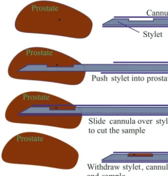
The equipment used in prostate biopsy includes an image-acquiring tool, also known as a transrectal ultrasound probe (TRUS), and a biopsy gun that samples the prostate (Pond-man et al., 2008) in a sequence illustrated in Fig. 1. In the first step, the tip of the needle is positioned proximal to the prostate, then a button is pushed on the biopsy gun that auto-matically performs the next three steps.
Figure 1.Tissue sampling procedure in four steps.
transrectal biopsy, the patient is seated in a lateral decubitus position; the TRUS probe is lubricated with a special anes-thetic gel and inserted into the rectum. The ultrasound probe provides real-time imaging of the entire prostate gland, en-abling the physician to select the prostate area to be sampled. Attached to the TRUS probe is a special guiding tool for the biopsy gun that will preserve the orientation of the needle in the echography plane, allowing for the continuous mon-itoring of the needle location. When the desired location is reached, the firing mechanism of the biopsy gun is actuated and the needle collects the tissue sample. After the sampling, the needle is extracted and the tissue is placed into a special container for further analysis. Typically a 12-core biopsy is performed in an attempt to cover the entire volume of the prostate, but the procedure is carried out in a blind manner due to the limited image quality and manual positioning ac-curacy of the system. Another drawback specific to the tran-srectal approach is the fact that the needle, in order to col-lect the tissue sample, has to pass through the rectum wall, thus easily generating serious infection causing the patient to be hospitalized for a certain period of time after the biopsy (Taneja et al., 2013).
Transperineal biopsy of the prostate implies a different protocol for the procedure. The patient is positioned in the gynaecological position (Free Education Network, 2016). The TRUS probe is lubricated and inserted into the rectum, as in transrectal biopsy, and used to visualize and guide the needles to the sampling positions in real time. The needles are inserted through the perineum in two possible scenar-ios: on multiple individual trajectories passing through the skin each time or on trajectories with a common point at which an incision is made through the skin (Taneja et al., 2013). The two approaches were compared experimentally and a detailed analysis is presented in Vaida et al. (2017). The results, presented in Fig. 2, point out an important dif-ference between the two approaches. When the needle passes
Figure 2.Experimental results of the needle incision procedure
with and without skin incision (Vaida et al., 2017).
through the skin, there is a force spike that does not appear in the second case. This indicates that the second approach of-fers better accuracy in avoiding possible needle bending and deflection from the ideal trajectory. From a medical point of view, the experimental data we collected was certified by the European Institute of Oncology in Milan, Italy, where doc-tors use the skin incision approach to perform transperineal biopsies of the prostate (de Cobelli et al., 2015).
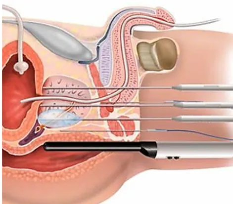
In a comparison between the two approaches, the advan-tage of the transperineal approach (Fig. 3) is better access over the prostate gland, especially for the sampling of the apex of the prostate (an area that cannot be reached transrec-tally). In the case of the transrectal approach, the needles are inserted through the base of the prostate (far from the apex) and the length of the sampled tissue has to be at least 10 mm to obtain proper material for analysis. At the same time, the transperineal approach eliminates the septic risk raised by the transrectal approach because the needle does not penetrate the intestines in order to collect the tissue (Pepe and Arag-ona, 2014).
The most commonly used procedure in prostate cancer diagnosis is the TRUS-guided prostate biopsy. However, this procedure has significant disadvantages. In general, the biopsy cores are clustered together, which raises the issue of optimal sampling of the entire prostate. Moreover, the pre-cise localization of possible lesions and the resampling of a region of interest are not possible with the standard free-hand TRUS biopsy technique. Since the cancer detection rate is correlated with the quality of biopsy core sampling, an improved core sampling technique should maximize the prostate cancer detection rate, which in turn leads to better disease management (Kaye et al., 2015).
guid-Figure 3.Transperineal approach to prostate biopsy (Avantgarde, 2016).
ance for common prostate cancer treatment methods (e.g., brachytherapy and radical prostatectomy; Kaye et al., 2015). Research centers around the world are trying to provide so-lutions for medical requirements in an attempt to improve lives through the construction of robotic systems (Gherman et al., 2016; Berceanu and Tarnita, 2010; Tarnita, 2016) or by studying and improving existing systems (Tarnita and Marghitu, 2013; Ottaviano et al., 2014; Berceanu et al., 2010).
In 2007, Cheng proposed a robotic system that allows for the transperineal approach to prostate biopsy (Cheng, 2007). In this system, the needle is placed at an angle with respect to the endorectal probe and set to collect different samples by modifying this angle. The robotic system is made up of two mechanical modules: the first module is for needle guidance, while the second module is for imagistic sampling. Both modules are mounted on a mobile platform with 5 DOFs. The needle is inserted manually and guided by the urologist, while the sampling depth is controlled by a switch mounted on the biopsy gun. The orientation mechanism of the needle and the switch are actuated. The imagistic sampling module is made up of an endorectal probe and its support mecha-nism that executes an active translation. The 5 DOF system offers sufficient dexterity to position the imagistic sampling module, but the tissue sampling is done manually.
Another solution for the transperineal approach is pro-posed by Long et al. (2012). The system includes a guid-ing module for the biopsy gun mounted on one side of the imagistic module. The system positions the needle on a spec-ified trajectory and fixes the sampling depth. The robot has 7 DOFs. A TRUS probe is attached to the ultrasound appara-tus. The guiding system of the needle is calibrated before the
endorectal probe procedure. The robot positions the module of the biopsy gun close to the perineum of the patient and the first needle is inserted. Once the needle has reached the sampling area, a position check is applied using the endorec-tal probe. If the position is not correct, the needle is retracted and reinserted correctly. This system does not have an auto-mated guiding device for the ultrasound probe, which is thus manually guided.
Stoianovici et al. propose an MRI-safe robot for biopsy of the prostate (Stoianovici et al., 2014). For this system, the transrectal approach is preferred. The robotic structure is ac-tuated with pneumatic stepper motors (PneuStep). The struc-ture has 3 DOFs, which is considered sufficient to guide the TRUS probe; 1 DOF is implemented separately and repre-sents a new method of biopsy needle insertion. The robotic structure assists the urologist by automatically orienting the biopsy gun to the targeted biopsy area and fixing the sam-pling depth using MRI. The robot is attached to the MRI ta-ble using a fixture plate after the patient has been seated in the necessary position for the medical procedure (lateral de-cubitus). The endorectal extension includes an MRI coil and a set of markers to memorize the patient position. The guided biopsy needle passes through the endorectal extension at an angle calculated by the robotic system. The system is pro-vided with a rotation joint around the endorectal extension, a rotation joint for needle guidance, and a translation joint for needle insertion. The insertion of the needle is done manu-ally, and only the depth of sampling and the orienting angles are fixed by the endorectal probe. The disadvantage of the system is the transrectal approach, which is a procedure that creates complications, as mentioned previously.
Another robotic system for transperineal prostate biopsy is proposed by Vaida et al. (2015). The robotic solution consists of a modular parallel structure with two independent kine-matic chains using a specific RCM (remote center of motion). The TRUS guidance module has 4 DOFs; with respect to en-try points, there are three rotations and a translation along the longitudinal axis of the probe. The module for manipu-lating the biopsy gun has only 3 DOFs since the rotation of the needle around its longitudinal axis is unnecessary. The first module of the TRUS probe is positioned on the biopsy table and the biopsy gun module is mounted on top of the first in an upside-down position with the same kinematic ap-pearance. The fourth active joint is replaced with a simple actuation device that triggers the biopsy gun. This system requires high-quality machining for the components of the RCM mechanism, which is sometimes difficult to achieve.
suspected cancer patient has been performed, the sampling points are marked by the urologist. The marked sampling points are then referenced in the robot reference system and the endorectal probe is inserted. After the volumetric image of the prostate is obtained, the sampling points are identified and the biopsy is performed. The advantage of this robotic system is that after the patient has been seated and calibrated with the robot reference system, the surgeon’s only task is to supervise the system, check the validity of the sampling points, and comply with the safety features of the system (ev-ery procedure performed by the robot has to be approved by the urologist).
The paper is organized as follows. Section 2 presents the novel parallel robotic system designed for prostate biopsy with its two modules and the inverse kinematic equations. Section 3 presents the singularities in the robotic system. In Sect. 4, the workspace of the robotic structure is presented. The simulation results of the parallel robot for transperineal biopsy are presented in Sect. 5. The experimental model of the robotic structure is presented in Sect. 6 followed by a set of experimental results in Sect. 7. The conclusions are pre-sented in Sect. 8, followed by acknowledgements and refer-ences.
2 BIO-PROS-1 parallel robot
In order to define the specific tasks of the robotic system for transperineal prostate biopsy, a medical protocol (for robotic-assisted prostate biopsy) was developed in collaboration with a team of oncologists from the University of Medicine and Pharmacy in Cluj-Napoca as a stepwise procedure.
1. The exact tumor location and size are determined with an MR imaging device, where a special smaller probe will be inserted through the urethra into the prostate as a fixed marker.
2. The MRI data are processed in order to establish the co-ordinates for the target points for the needle, calculated relative to the special probe.
3. The patient is positioned in the gynecological position.
4. Anesthesia is administered; the transperineal approach involves a local anesthetic of the perineum, the area through which the needle is inserted.
5. The robot is positioned relative to the patient and the coordinate systems of the patient and robot are corre-lated with all the necessary transformations (from this moment on, the robot will remain fixed with respect to the patient).
6. The TRUS probe is inserted for real-time image acqui-sition along with the same special smaller probe placed inside the prostate. The probe will be used for the MRI– TRUS fusion to ensure that the coordinates determined
as target points will be properly defined during the biopsy.
7. The exact locations of the points are recalculated based on the MRI–TRUS fusion image (the prostate is modi-fied in shape due to the different positions of the patient inside the MRI and during the procedure).
8. The sampling is performed using the target point coor-dinates determined in step 7, with real-time monitoring of the enhanced images using one of the two main op-tions for the definition of the insertion points locaop-tions.
9. A needle-guiding template is used, which allows the needles to be driven on parallel trajectories in different areas of the prostate.
10. A single entry port is also used, which is created by a very small incision in the skin situated on the median line of the body to drive the needles on concurrent tra-jectories (Vaida et al., 2017).
11. The biopsy gun is driven to the insertion point by the robotic system with the final orientation (calculated based on the insertion target coordinates pairs).
12. The needle actuation module is engaged to insert the needle (on a linear path) until the target point is reached.
13. The needle actuation module activates the sampling function of the biopsy gun, thereby sampling the tissue.
14. The needle actuation module retracts the needle on the same trajectory until the needle is out of the patient, at which time the robot arm moves away from the patient to enable the unloading of the gun and the sample re-trieving.
15. The samples are stored in special containers (small bot-tles with identification tags for the sampling area).
After the sampling, anatomopathological analysis of the tissue is performed to determine the possible presence and spread of cancerous cells in the prostate.
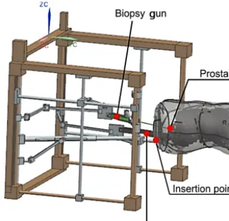
The robotic system should guide both the TRUS and the biopsy gun, and hence there are two main modules, one for each instrument (Fig. 4). The kinematics of the BIO-PROS-1 parallel robotic structure have been presented in Pisla et al. (2015).
Figure 4.Simplified CAD model (concept) of BIO-PROS-1.
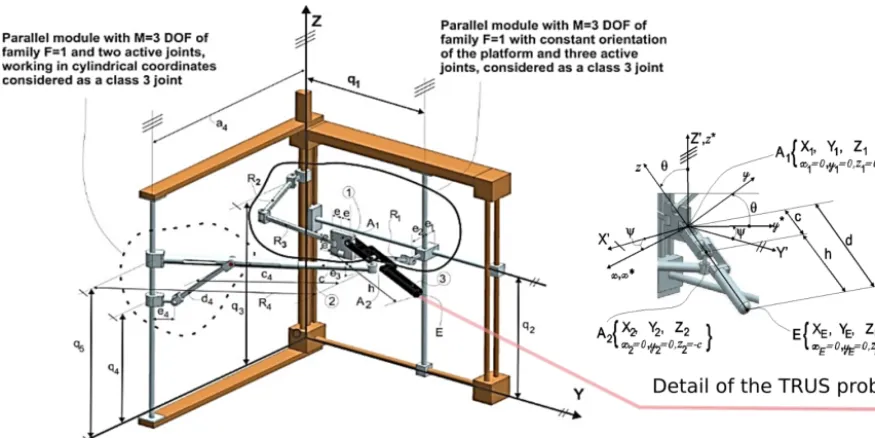
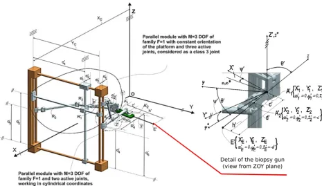
F =1 (the number of imposed constraints for 1 DOF; com-mon to all links of the mechanism) with three active joints (q1, q2, q3). The second parallel module isM=3 DOFs of familyF =1 with two active joints (q4, q5); it works in cylin-drical coordinates. A fixed coordinate system (OXY Z) is de-fined and attached to the frame of the robot (Fig. 5), where theOZaxis represents the translational axis of the (q3) trans-lational joint, and theOY axis is parallel to the (q1) transla-tional joint. With respect to this coordinate system, the first module is positioned in the OY Z plane, while the second module is at a distance (a4) with the active joints (q4, q5) moving on an axis parallel toOZ. The second robotic mod-ule, used for guiding the biopsy gun, has the same kinematic structure as the first; however, as can be seen from Fig. 6, it has both modules in the same plane. With respect to the fixed coordinate system, OXY Z is parallel to theOY Z plane at a distance (XC). Both robotic modules have active transla-tional joints actuated along axes parallel to theOY (q1and
q10) andOZ (q2, q3, q4, q5,q20, q30, q40, q50) of the fixed frame of the robot. Each pair of modules (composing the TRUS guiding module and the biopsy-gun guiding module) is con-nected through a pair of Cardan joints that hold the mobile platform, which further integrates the active instruments. The geometric parameters of the TRUS-probe guiding module are as follows:
R1, R2, R3, c4, d4, h − fixed link lengths;
e, e1, e2, e3, e4 − distances between the rotational axes of passive joints;
c − distance between the two Cardan joints (A1andA2).
The geometric parameters of the biopsy-gun guiding mod-ule are as follows:
R10, R20, R30, c04, d40, h0 −fixed link lengths;
e0, e10, e02, e03, e40 − distances between the rotational axes of passive joints;
c0 − distance between the two Cardan joints (A01andA02).
The inverse geometric model of the TRUS guiding module is determined based on simple analytical equations: know-ing the TRUS position, the tip pointE(XE, YE, ZE) and its orientation, and the anglesψandθ. The generalized coordi-nates are presented in Eqs. (1) to (5):
q1=YE−(h+c)·sin (θ)·sin (ψ)−e, (1)
q2=ZE+(h+c)·cos (θ)+e (2) +
q
R12−(XE−(h+c)·sin (θ)·cos (ψ)−e1−e2)2,
q3=ZE+(h+c)·cos (θ), (3)
q4=ZE+h·cos (θ)−e3, (4)
q5=ZE−h·cos (θ)−e3+ q
d42−(R4−c4−e4)2. (5) The generalized equations for the direct kinematic model of the TRUS guiding module are
XE=XA1+d·sin (θ)·cos (ψ) YE=YA1+d·sin (θ)·sin (ψ) ZE=ZA1−d·cos (θ)
, (6)
θ=acos
ZA1−ZA2 c
(7)
ψ=atan2 YA2−YA1, XA2−XA1 , where
XA1=e1+e2+ q
R12−(q2−q3−e)2
YA1=q1−e ZA1=q3
. (8)
By solving the system of equations (Eq. 9), the expressions forXA2, YA2, ZA2 can be obtained:
c2− ZA1−ZA2 2 = YA2−YA1
2
+ XA2−XA1 2 XA2−e5
2
+ a4−YA2 2 =
e4+c4+ q
d42−(q5−q4)2 2 ZA2=q4+e3
. (9)
Equation (9) is a quadratic equation leading to a double solu-tion forXA2andYA2, which define the two possible working modes of the robotic system.
The equations that characterize the inverse kinematic model of the biopsy gun module for BIO-PROS-1 are de-scribed in Eqs. (10) to (14):
q01=Y0E− h0+c0·sin θ0·sin ψ0−e0, (10)
q02=Z0E+ h0+c0
·cos θ0+e0 (11)
+ q
R102−(X0
Figure 5.Kinematic model of the TRUS-probe guiding module.
q03=Z0E+ h0+c0·cos θ0, (12)
q04=Z0E+h0·cos θ0−e03, (13)
q05=Z0E−h0·cos θ0
−e03 (14)
+ q
d024−(R0
4−c04−e04)2.
Using the direct kinematic model, the equations that char-acterize the needle tip coordinates and the orientation of the biopsy gun are presented in Eqs. (15) to (18):
XE0=XA0
1
+d0·sin θ0·
cos ψ0 YE0=YA0
1+d
0·sin θ0
·sin ψ0
ZE0=Z
A01−d0·cos θ0
, (15)
θ0=acos Z
A0
1 −ZA02
c0
(16)
ψ0=atan2YA02−YA0
1, XA
02−XA0
1 , where X0
A1=XC−e
0
1−e02−
q R02
1− q02−q03−e0
2
Y0A1=q01−e0 Z0A1=q03
. (17)
By finding the solutions for the system of equations (Eq. 18), the expressions forX0A2, Y
0 A2, Z
0
A2 are obtained:
c02− Z0A1−Z 0
A2 2 = Y0A2−Y
0 A1
2
+ X0A2−X 0
A1 2 XC−e05−X0A2
2 +Y02A
2
=
c04+e04+ q
d024− q0 5−q04
2 2 Z0A2=q
0 4+e03
. (18)
An analysis of Eq. (18) reveals that in the case of the sec-ond module, the coordinates forX0A2 andY
0
A2 also have a double solution, leading to the two working modes of the robot module.
3 Singularity analysis of the parallel robot BIO-PROS-1
The singularities in the parallel manipulators can be studied using different mathematical techniques, such as analyzing the Jacobian matrix (of the loop closure equations) rank and condition number (Merlet, 2006), using screw theory (Zla-tanov et al., 2002), using a study parameterization of the Eu-clidian displacement group (Walter and Husty, 2010), or us-ing the augmented Jacobian matrix (Joshi and Tsai, 2002). A parallel robot in singular configurations can instantaneously lose the ability to transmit motion and become uncontrollable (Plitea, 2015b) in two possible cases: the mechanism loses its stiffness by gaining DOFs, or the mechanism locks by losing DOFs (Podder et al., 2010). Identification and avoidance of the singular loci is crucial in ensuring kinematic accuracy and robotic system stability.
Figure 6.Kinematic model of the biopsy-gun guiding module.
Singularity analysis therefore has great importance in order to identify and avoid singular loci in the robot workspace (Gherman et al., 2010). The method used in this paper for the singularity analysis is based on evaluating the determinants of the Jacobian matricesAandB, which are obtained from the inverse and direct geometric models of the robot (Gos-selin and Angeles, 1990; Gos(Gos-selin and Wang, 1997). This groups them into three categories: serial singularities (the de-terminant of the Jacobian matrix for the inverse kinematic problem is zero and the robot losses degrees of mobility); parallel singularities (the determinant of the Jacobian matrix for the direct kinematic problem is zero and the robot gains degrees of freedom, becoming uncontrollable); and architec-tural singularities (the determinant of the Jacobian matrix for both kinematic problems are zero and the end effector can be moved while all the active joints are locked).
Starting from the geometric models that describe the relations between the coordinates of the active joints
q10, q20, q30, q40, q50 and the coordinates of the tip of the needle,
E=(XE, YE, ZE, ψE, θE), as shown in Pisla et al. (2015). The implicit functions can be defined by Eq. (19) for the TRUS probe module and Eq. (20) for the biopsy gun mod-ule:
f1:YE−d·sin (θ)·sin (ψ)−e−q1=0;
f2:ZE+d·cos (θ)−2·e −
q
R12−(XE−d·sin (θ)·cos (ψ)−e1−e2)2 −q2=0;
f3:ZE+d·cos (θ)−e−q3=0;
f4:ZE+h·cos (θ)−e3−q4=0;
f5:
c4+e4+ q
d2
4−(q5−q4)2
2
−(a4−XE+h·cos (ψ)·sin (θ))2
+(YE−h·sin (ψ)·sin (θ)−c4−e4)2−q5=0,
(19)
f1:Y0E−d0·sin θ0
·sin ψ0−e0−q01=0;
f2:Z0E+d0·cos θ0
+2·e0 +
q
R012−(XC−X0E+d0·sin (θ0)·cos (ψ0)−e01−e02)2 −q02=0;
f3:Z0E+d0·cos θ0−q03=0;
f4:Z0E+h0·cos θ0
−e0
3−q04=0;
f5:
c04+e04+ q
d02
4− q05−q04
2 2
−(XC−XE+h·cos (ψ)·sin (θ)−e5)2 −(YC−YE−h·sin (ψ)·sin (θ))2=0.
(20)
The equation describing the kinematic model for the ve-locities of the ultrasound-guiding robotic module is pre-sented in Eq. (21),
A· ˙X+B· ˙q=0, (21)
whereX˙ represents the velocity vectors of the ultrasound tip andq˙the velocity vector of the active joints:
˙
X=X˙E,Y˙E,Z˙E,ψ,˙ θ˙ T
, q˙=q˙1,q˙2,q˙3,q˙4,q˙5
T
AandBare Jacobian matrices obtained using Eqs. (23) and (24): A=
0 1 0 ∂f1
∂ψ ∂f1
∂θ ∂f2
∂XE
0 1 ∂f2
∂ψ ∂f2
∂θ
0 0 1 0 ∂f3
∂θ
0 0 1 0 ∂f4
∂θ ∂f5
∂XE
∂f5
∂YE
0 ∂f5
∂ψ ∂f5 ∂θ , (23) B=
−1 0 0 0 0
0 −1 0 0 0 0 0 −1 0 0 0 0 0 −1 0
0 0 0 ∂f5
∂q4 ∂f5 ∂q5 , (24) where ∂f1
∂ψ = −d·cos (ψ)·sin (θ), (25) ∂f1
∂θ = −d·sin (ψ)·cos (θ), (26) ∂f2
∂XE
= e1−XE+e2+d·cos (ψ)·sin (θ) q
R12−(e1−XE+e2+d·cos (ψ)·sin (θ))2
, (27)
∂f2
∂ψ =d·sin (ψ)·sin (θ) (28)
· (e1−XE+e2+d·cos (ψ)·sin (θ)) q
R12−(e1−XE+e2+d·cos (ψ)·sin (θ))2
,
∂f2
∂θ = −d·sin (θ) (29)
−d·cos (qψ)·cos (θ)·(e1−XE+e2+d·cos (ψ)·sin (θ)) R12−(e1−XE+e2+d·cos (ψ)·sin (θ))2
,
∂f3
∂θ = −d·sin (θ), (30) ∂f4
∂θ = −h·sin (θ), (31) ∂f5
∂XE
=2·(a4−XE+h·cos (ψ)·sin (θ)), (32)
∂f5
∂YE
=2·(h·sin (ψ)·sin (θ)−YE), (33)
∂f5
∂ψ =2·h·sin (ψ)·sin (θ)·(a4−XE+h·cos (ψ) (34) ·sin (θ))+2·h·cos (ψ)·sin (θ)·(YE−h·sin (ψ)·sin (θ)) ∂f5
∂θ =2·h·sin (ψ)·cos (θ)·(YE−h·sin (ψ)·sin (θ)), (35) +2·h·cos (ψ)·cos (θ)·(a4−XE+h·cos (ψ)·sin (θ)),
∂f5
∂q4 =
−2·(q4−q5)·
c4+e4+ q
d42−(q4−q5)2
q
d42−(q4−q5)2
,
(36)
∂f5
∂q5 =
2·(q4−q5)·
c4+e4+ q
d42−(q4−q5)2
q
d42−(q4−q5)2
. (37)
The determinant of theAJacobian matrix of the inverse kinematic model for the TRUS probe module is defined by the expression
det(A)=2·c 2·t
1·t2
t3
, (38)
where
t1=sin (θ)2·[YE·cos (ψ)−XE·sin (ψ)+a4·sin (ψ)], (39) t2=e1−XE+e2+(c+h)·cos (ψ)·sin (θ), (40) t3=
q
R21−(XE−(h+c)·sin (θ)·cos (ψ)−e1−e2)2. (41)
The singularity condition is satisfied when det(A)=0. This determinant vanishes in the following cases.
a. c=0.
The term “c” is a geometric parameter that defines the dis-tance between the two Cardan joints, always taking values greater than zero. If “c” becomes zero, the two Cardan joints would superpose, changing the geometry of the robot. This case is purely theoretical and will not occur.
b. sin (θ)=0, leading toθ=0 orθ=π.
This expression implies that the TRUS probe is placed ver-tically, parallel to theOZaxis and oriented with the tip of the probe downwards (θ=0) or with the tip of the probe up-wards (θ=π). Because of the relative position between the robot and the patient, the TRUS probe will always work close to the horizontal planeθ=π/2 (Fig. 7). Furthermore, in the design parameters of the robot, the geometric dimensions of the elements do not allow for the vertical positioning of the TRUS probe. Thus, this singularity is eliminated in the de-sign stage.
c. (YE·cos (ψ)−XE·sin (ψ)+a4·sin (ψ))=0, leading to
tan (ψ)= YE XE−a4
. (42)
Figure 7.Working mode of BIO-PROS-1.
Figure 8.Singular position (c) of the TRUS probe module.
c4, d4, c, and h are in the same plane. This position rep-resents the plane that separates the two working modes of the robotic module emerging from the double solution for Eq. (9). To avoid this singular configuration, the follow-ing condition must be implemented into the robot control:
ψ <atan2 (YE, XE−a4). This will ensure that the robot will not change its working mode during functioning.
d. e1−XE+e2+(c+h)·cos (ψ)·sin (θ)=0, leading to the expression
XA1−e1−e2=0. (43)
This configuration is presented in Fig. 9 and implies that the link R1 is positioned into a parallel plane with the Y OZ plane. To avoid this configuration when implementing the control module of the robot, the next condition can be im-plemented:
XA1> e1+e2. (44)
This configuration (Fig. 10) appears when the linkR1is nor-mal to theY OZplane (or is positioned into a parallel plane toXOY). As in the previous case, given the fact that the sin-gularity is on the boundary of the module workspace, the
fol-Figure 9.Singular position (d) of the TRUS probe module.
Figure 10.Singular position (e) of the TRUS probe module.
lowing mechanical constraint can be imposed on the control module of the robot:
R12> XA1−e1−e2 2
. (45)
In conclusion, the singularity cases (a), (b), (d), and (e) are all at the workspace boundary. This is also demonstrated in the figures that represent each singularity, where the robot links are either fully extended or fully retracted relative to the
OXY Zframe. The only singular pose that has to be avoided (since it is located inside the robot workspace) during the robot operation is described in case (c).
Next, the determinant of the direct kinematic model is an-alyzed. The general expression is
det (B)= −
2 (q4−q5)
c4+e4+ q
d42−(q4−q5)2
q
d42−(q4−q5)2
The cases for which this determinant becomes zero are de-tailed below.
a. q4−q5=0.
This expression implies thatq4=q5, meaning that the two active joints are overlapping. This singularity case is elimi-nated in the design phase since the robot mechanical struc-ture will prohibit the values of the two active joints from be-coming equal. By mounting a position sensor on one of the joints, the possibility of collision is also eliminated.
b. d42−(q4−q5)2=0.
The determinant of matrixBbecomes zero when thed4link is in the vertical position (parallel to theOZaxis). This po-sition can be eliminated by imposing the condition that the distance between joints q4 and q5 is lower thand4 on the control module of the robot.
c. c4+e4+ q
d42−(q4−q5)2=0.
Considering the condition imposed for the singularity (b), the left-hand side of this equation contains only positive terms. This means that this equality will never occur.
As a general overview, for the determinant of matrixB, the singular cases appear only at the boundary of the workspace; thus, through adequate design and control, they can be easily avoided without any negative influence on the behavior of the robot.
The equations for the biopsy gun module are very close to the ones for the first module, with very little variation in expression. They will be presented briefly. The determinant of the inverse kinematic problem for the biopsy gun module is given by the expression
det(A0)=2·c 02·t
1·t2
t3
, (47)
where
t1=sinθ02·(YC−YE0)·cosψ
02−(X
C−XE0 −e
0
5)·sinψ
0, (48)
t2=(XC−e10−X
0
E−e
0
2+(c
0+
h0)·cosψ0·sinθ0, (49) t3=
q
R012−(XC−X0E+(h0+c0)·sin (θ0)·cos (ψ0)−e01−e02)2. (50) There are also five cases for which this expression be-comes zero.
a. c0=0.
The termc0 is a geometric parameter (the distance between the two Cardan joints) and has a positive dimension imposed by the architecture of the robot.
b. sin θ0=0, leading toθ0=0 orθ0=π.
This expression implies that the biopsy gun is placed ver-tically, parallel to the OZ axis oriented with the tip of the
Figure 11.Singular position (c) of the biopsy gun module.
needle downwardsθ0=0) or with the tip of the needle up-wards (θ0=π). Because of the relative position between the robot and the patient, this position cannot be reached, as seen in Fig. 10; the working position of the probe is close to the horizontal plane.
c. YC−Y0E·cos ψ0− X0C−X0E−e05·sin ψ0 =0,
leading to
tan ψ0= Y 0
C−Y0E
X0
C−X0E−e05
. (51)
Figure 11 represents this type of configuration translated in the positive direction of theOXaxis. Practically, this con-figuration implies that linksc04, d04, c0, andh0are in the same plane. This configuration defines the boundary between the two working modes of this robotic module (defined by the double solution in Eq. 18).
d. XC−e01−X0E−e02+ c0+h0·cos ψ0·sin θ0=0, leading to
X0A1−e 0
1−e02=0. (52)
This configuration is illustrated in Fig. 12 and implies that the linkR01is positioned into a parallel plane with theY OZ
plane. To avoid this configuration when developing the con-trol module of the robot, the next condition can be imple-mented:
X0A 1 > e
0
1+e02. (53)
This will reduce to the expression
R102− X0A1−e 0
1−e02. 2
=0. (54)
Figure 12.Singular position (d) of the biopsy gun module.
to XOY), represented in Fig. 13. As in the previous case, given the fact that the singularity is at the boundary of the workspace of the module, the following mechanical con-straint can be imposed on the control module of the robot:
R102> X0A1−e 0
1−e022. (55)
The determinant of matrixBfor the biopsy gun is the same as the determinant of matrixBfor the endorectal probe mod-ule. The same singularities are obtained with all poses lo-cated on the workspace boundary:
det B0= −
2 q04−q 0
5
c04+e04+ q
d02
4− q04−q05
2
q
d02
4− q
0
4−q05
2
. (56)
4 Workspace analysis of the parallel robot BIO-PROS-1
In the case of the ultrasound probe guidance, the robot workspace depends on the insertion point into the anus (I) and thus on the relative position of the patient to the robot. Once this point’s coordinates are defined (either by visual guidance or by using an external marker and calibrated ta-ble for the robot), the ultrasound probe will have a spherical motion around this point that acts as a remote center of mo-tion (RCM)), reaching a large number of target points and orientations. For the workspace generation, an inverse kine-matic model was used. An initial volume, in the shape of a parallelepiped, is defined to obtain a range of values for each coordinate. Further on, each point is tested; if validated,
Figure 13.Singular position (e) of the biopsy gun module.
it is saved as a point in the robot workspace. The same ap-proach is used for the biopsy gun module, by considering the approach with a single insertion point for each sampling. Supplementary conditions are introduced between the rela-tive positions of the two modules based on the restrictions imposed by the medical procedure. The conditions imposed refer to the following:
1. the maximum and minimum stroke values for the robot active joints (q1, q2, q3, q4, q5for the TRUS probe mod-ule andq01, q02, q03, q04, q05 for the biopsy gun mod-ule);
2. the distanceI T maximum value (the depth value of the probe introduced into the body) should be less than or equal to the probe length;
3. the distanceI0T0that represents the length of the needle inserted into the body must not exceed the total length of the needle;
4. the value intervals of the orientation angles should be 60◦< ψ <120◦ and 45◦< θ <135◦ (according to medical experts);
5. singular configurations and singularity points have to be avoided by imposing the mathematic conditions abs (det (A)6=0) and abs (det (B)6=0) (Pisla, 2015);
6. the robotic structure should avoid positions in which one or more links of the robots would collide (ZE0 > ZE andZA0
1> ZA1);
7. and the workspaces of the TRUS-probe guiding module and the biopsy gun guiding module should not intersect.
Figure 14.Ultrasound probe and biopsy gun workspace for a given insertion point.
the procedure) andT (the target point of the probe inside the colon in order to provide proper imaging of the target point for the sampling, which will have a range of coordinates in-side the body, limited by the insertion point coordinates and the probe length). In the case of the biopsy-needle guidance robot, the workspace is largely dependent on the pair of in-sertion target points: I0 (the needle insertion point into the perineum) andT0(the target point into the prostate tumor). Once these points have been chosen and their coordinates become known, the needle will be positioned at the insertion point with its final orientation (the anglesψ andθ). After-wards it will be inserted on a linear trajectory up to the target point. Figure 14 presents the robot workspace for an inser-tion pointI (for the ultrasound probe) andI0(for the biopsy gun), for which all the possible target locations for the two instruments, based on the set of restrictions, have been com-puted.
The geometrical parameters have the following contively chosen values as a result of designing the robotic struc-ture on a real scale.
a. For the ultrasound-probe guidance robot:
R1=305 mm;e=27.5 mm;e1=65 mm;e2=20 mm;
e3=30 mm;
e4=60 mm;c=80 mm;h=185 mm;c4=365 mm;
d4=190 mm;
a4=655 mm.
b. For the biopsy-needle guidance robot:
R01=305 mm;e0=27.5 mm;e01=65 mm; e02=20 mm;e30 =30 mm;
e04=60 mm;e50 =40 mm;c0=80 mm;h0=185 mm; c04=365 mm;
d40 =190 mm;a4=655 mm;XC=760 mm;
YC=600 mm.
The insertion points have the following coordinates:
I XI=360 mm;YI=520 mm;ZI=150 mm, I0 X0I= 365 mm;Y0I=500 mm;Z0I=220 mm. These are indi-cated by the blue points on the figure; the red represents the valid points with respect to the given insertion point (I andI0), and the green represents the points that cannot be reached from the insertion points due to the mechanical configuration of the structure. As presented above, the workspace was computed inside a parallelepiped shape defined by the range of all active joints; because all compu-tations were made using the RCM, all the points are shaped into a sphere with a center in the insertion points (I andI0; the insertion point is fixed and the motion is around this point).
5 Simulation of parallel structure BIO-PROS-1
By using the inverse kinematic models presented in Pisla et al. (2015), a medically relevant scenario has been simulated in a program created using Matlab. The motions are simi-lar for both robots (TRUS and the biopsy gun). The robotic system and the patient are positioned and the robot coordi-nate system is correlated with that of the patient based on several markers. After both robotic modules have been ini-tialized (the coordinates of all the joints are known), the sam-pling procedure begins. First the TRUS probe moves towards the insertion point. This point is marked on the body; for the TRUS probe, this is the anus. After the insertion point for the probe has been reached the probe moves towards a pre-set target point inside the rectum, which represents the point that gives the best view of the sampling area of the prostate. To reach the target point, given the fact that the probe moves inside the patient, the motion parameters (speed and acceler-ation) are significantly lower than the motion parameters of the motion towards the insertion point of the probe.
Figure 15.BIO-PROS-1 active coordinate time diagram for positions, speeds, and accelerations for the TRUS-probe guiding module.
Figure 17.Biopsy gun holder.
Figure 18.TRUS probe holder.
a small cross incision to reduce the tissue resistance force (as described in the Introduction). Based on the pairs of coor-dinate points (insertion target), the robot calculates the dle orientation. When the insertion point is reached, the nee-dle has the final orientation to enable its motion inside the body on a linear path. The target point is represented by the sampling area on the prostate. The motion towards the target point of the needle is a strictly linear motion along the nee-dle axis; as in the case of the probe, the motion parameters are lowered. After the target point of the needle has been validated via an ultrasound image provided by the TRUS probe, the biopsy gun is triggered and the needle samples the prostate. With the sampled tissue inside the cannula of the biopsy gun (see Fig. 1), the needle is retracted on the same linear trajectory.
For the simulation, the starting points and orientations were chosen as follows.
– Starting pose for the ultrasound probe:
XC=180 mm;
YC=470 mm;
ZC=100 mm;
ψ=90◦;
θ=80◦. (57)
– Starting pose for the biopsy needle:
X0C=380 mm;
Y0C=570 mm;
Z0C=160 mm;
ψ0=90◦;
θ0=80◦. (58)
The two pairs of insertion target points for the two robots are as follows.
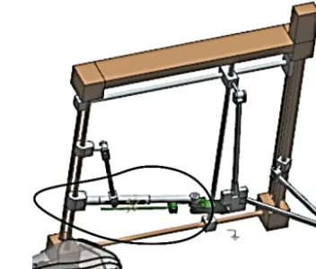
Figure 19.Biopsy gun module.
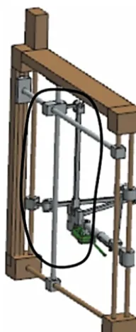
Figure 20.TRUS probe module.
– For the ultrasound probe:
XI=370 mm;
YI=530 mm;
ZI =85 mm;
XT =370 mm;
YT =600 mm;
ZT =110 mm.
(59)
– For the biopsy gun:
X0I =390 mm;
Y0I=530 mm;
Z0I=120 mm;
X0T =380 mm;
Y0T =590 mm;
Z0T =125 mm.
(60)
The orientation for the two guided elements can be derived from the insertion and target point coordinates:
ψI T =atan2 (YT−YI, XT−XI), θI T =atan2
p
(YI−YT)2+(XI−XT)2, ZI−ZT
Figure 21.BIO-PROS-1 experimental model.
The motion parameters are the same for both robotic mod-ules: νmax=20 mm s−1andamax=10 mm s−2 for the first stage of the motion (position and orientation of the guided elements at the insertion points) andνmax=2.4 mm s−1and
amax=1.2 mm s−2 for the second stage during which the probe and needle are inserted into the body (at the speeds required by urology specialists for safety reasons).
Figures 15 and 16 present how the final motion is achieved by assessing the motion (position, speed, and acceleration) for each active joint: at a higher speed and acceleration, the guided elements are positioned at the insertion points in the body and achieve their final orientation. Afterwards, at a slower speed and acceleration, the probe and needle are guided on a linear trajectory inside the patient (Pisla et al., 2015).
6 Experimental model of parallel structure BIO-PROS-1
In order to perform experimental tests using the BIO-PROS-1 robotic structure, an experimental model of the robotic sys-tem was designed. The main purpose of the robotic structure is to manipulate the two instruments used in the transper-ineal prostate biopsy: the biopsy gun (Fig. 17) (Vaida et al., 2017) and the TRUS probe (Fig. 18). The first step in the development of the experimental model was the design of the biopsy gun module and the geometrical parameters of the mobile platform to guide an ultrasound probe. In order to design the two instruments, real models of the instruments were analyzed. For the biopsy gun, the Bard Monopty 22 mm (Bard Biopsy, USA) was selected and the Endocavity Bi-plane E14CL4b (BK Ultrasound, USA) was selected for the TRUS probe.
Analyzing the properties (mass, size) of the two instru-ments resulted in the design eleinstru-ments of the robot (Figs. 19 and 20). Both modules were linked together through a frame and assembly organs. Each active joint was materialized through a ball screw axis (10 in total, 5 for each module) and each axis was actuated using a stepper motor (10 in to-tal). For each passive rotational joint, radial-axial bearings
Figure 22.BIO-PROS-1 testing: ballistic gel cube with spheres.
were selected to fulfil the motion requirements, and bearing housings were chosen for passive translational joints.
The result of the experimental design was a rigid and mod-ular robotic structure able to fulfil the requirements for a robotic-assisted transperineal prostate biopsy. The overall mensions of the structure resulted from combining the di-mensions given by medical staff and the didi-mensions from computing the design parameters of the real model in order for the structure to manipulate the instruments in a safe envi-ronment.
The final result of the development of the parallel robotic structure BIO-PROS-1 can be seen in Fig. 21. The material used for the frame is an aluminum alloy, which is both rigid and low weight. For the motion axes, chrome steel was an applicable solution, while some parts were constructed using a rapid metal casting process.
7 Experimental data for the biopsy task
In order to evaluate the robot accuracy, a cube made of ballis-tic gel was created with spheres of different diameters placed inside in a well-defined pattern (Fig. 22). The robot task was to insert the biopsy needle inside a sphere. The silicone cube has an overall size of 150×100×100 mm and the coordi-nates of the spheres are as follows, also listed in the Table 1. A set of 10 consecutive runs was made for each sphere to demonstrate that the robot can reach each of them. This initial set of experimental runs validated the robot accuracy in the range of 2 mm, which is the size of the smallest sphere reached inside the cube. For the spheres with diameters of 2 mm, there were some target misses in the first runs, but following calibration the spheres were reached each time.
Figure 23.Prostate carcinoma detected using sonoelastography in different areas of the prostate (arrows show tumoral areas; Giurgiu et al., 2011; Dudea et al., 2011).
Table 1.Overall size and coordinates of the spheres.
No. Sphere diameter size [mm] X[mm] Y [mm] Z[mm] Achieved
1 5 [mm] 120 20 25 10/10
2 5 [mm] 75 10 25 10/10
3 2 [mm] 25 20 25 9/10
4 2 [mm] 60 25 80 8/10
5 2 [mm] 90 25 80 9/10
Step 1: the Faro Arm has been fixed with respect to the robotic system. Using the laser head (noncontact), the coordinate system of the robot has been determined.
Step 2: using the same laser head, the TRUS probe and biopsy needle have been scanned to determine the tip coordinates and its orientations.
Step 3: data obtained in step 2 have been compared with the CAD model of the robotic system, and an error has been computed.
Step 4: steps 2 and 3 have been performed several times and a database has been created (two sets of results are presented in Table 2).
In real medical scenarios using relevant coordinates for the transperineal prostate biopsy, a set of five consecutive mea-surements were performed for each set of points. Two differ-ent distances were imposed between the insertion points of the biopsy needle and the ultrasound probe to simulate differ-ent human anatomies. Based on sonoelastography ultrasound data on a malignant prostate (Giurgiu et al., 2011; Dudea et al., 2011), illustrated below (Fig. 23; the white arrow), two sets of coordinates for the input data were established in the robot coordinate system, considering that the patient is posi-tioned in the gynaecological position aligned to the symme-try line of the robot. In a real scenario, the coordinate transfer
would be achieved by using external markers on the patient and an internal marker placed through the urethra in the cen-ter of the prostate.
A surgical prostate biopsy performed manually by a urol-ogist has a statistical accuracy of 9 mm (Kaye et al., 2015). After experimental tests with the presented robotic system, the accuracy of the procedure has been determined between 1 and 2 mm. The results are similar to those presented in Krieger et al. (2005) and Susil et al. (2006). The next step in the robot development is its testing on a human phantom with an elasticity similar to human tissue. For better results, an innovative algorithm for trajectory planning, like the one presented in Girbacia et al. (2017a, b), may be used.
8 Conclusions
be-Table 2.Coordinates of target points.
TRUS module coordinates [mm] Needle module coordinates [mm]
Set no. Insertion Target Insertion Target
X Y Z X Y Z X Y Z X Y Z
1 250 800 420 250 900 430 250 800 460 260 895 452 2 250 800 420 250 880 425 250 800 460 238 875 443
Measured data, set 1: TRUS module coordinates [mm]
Mes. no. Insertion Error Target Error
1 250.68 800.66 420.50 1.07 250.95 899.75 428.87 1.26 2 250.73 800.32 419.30 1.06 249.31 900.51 429.27 1.03 3 249.99 800.50 419.40 0.78 251.05 900.38 430.37 1.31 4 250.14 799.77 419.17 0.87 250.39 898.85 429.04 0.95 5 250.46 800.33 420.74 0.93 250.59 899.63 429.71 1.00
Measured data, set 1: needle module coordinates [mm]
Mes. no. Insertion Error Target Error
1 249.85 800.22 459.04 1.00 259.46 894.45 452.81 1.13 2 249.51 800.95 460.62 1.24 260.15 894.85 451.82 1.15 3 250.03 800.53 460.40 0.66 260.86 894.68 451.30 1.08 4 249.36 799.38 460.86 1.23 259.97 894.42 452.66 1.06 5 249.39 799.04 460.35 1.19 260.37 895.04 452.51 1.09
Measured data, set 2: TRUS module coordinates [mm]
Mes. no. Insertion Error Target Error
1 250.95 800.36 420.68 1.22 249.75 881.16 424.62 0.81 2 249.54 799.34 419.59 0.91 250.34 881.09 425.26 0.85 3 250.41 800.29 419.67 0.60 250.57 880.21 425.31 0.72 4 250.87 800.80 419.01 1.54 248.98 879.71 424.38 1.63 5 250.29 799.09 419.89 0.96 249.62 879.48 424.74 0.99
Measured data, set 2: needle module coordinates [mm]
Mes. no. Insertion Error Target Error
1 249.30 799.04 460.56 1.32 237.99 874.42 442.62 1.12 2 249.11 799.26 460.36 1.21 239.10 874.34 443.76 1.37 3 250.60 799.83 459.78 0.66 237.83 874.69 443.69 0.32 4 250.46 800.65 460.47 0.92 239.02 874.97 443.62 1.30 5 250.60 800.40 460.57 0.92 238.88 874.28 442.72 1.12
tween the robot links. The singularity configurations of the robotic system have been analyzed and solutions for avoiding them have been provided; these are ready to be introduced into the robot control. The experimental model of the struc-ture has been developed and presented. A set of experiments was performed in order to validate the robotic structure. Based on the resulting errors, some improvements will be proposed and consequently applied to the mechanical struc-ture and the control system of the robot, followed by a new set of experimental tests on phantom models. The state of the art in robotic-assisted biopsy includes solutions that com-bine the motion of the TRUS probe with that of the biopsy gun. In some solutions, only the endorectal probe is
of the prostate is performed. The target points on the prostate are identified and marked as reference points and position markers are mounted on the body. When the biopsy proce-dure starts, the MRI is projected onto the robotic system user interface, and the ultrasound image from the TRUS probe is overlapped (with respect to the same position markers used during the MRI). Using this fusion system, the number of samples is reduced to a minimum (the number of points iden-tified during the MRI).
Data availability. All data used in this paper can be obtained on
request from the corresponding author.
Competing interests. The authors declare that they have no
con-flict of interest.
Acknowledgements. This paper was supported by no. 247/2014,
code PN-II-PT-PCCA-2013-4-0647 for the project entitled “ROBOCORE: Robotic assisted prostate biopsy, a high accuracy innovative method” and by no. 59/2015, code PN-II-RU-TE-2014-4-0992 for the project entitled “ACCURATE: A multi-purpose needle insertion device for the diagnosis and treatment of cancer.” Both were financed by UEFISCDI.
Edited by: Chin-Hsing Kuo
Reviewed by: two anonymous referees
References
ACS: The American Cancer Society’s website, available at: http://www.cancer.org/research/cancerfactsstatistics/ cancerfactsfigures, last access: January 2016.
Avantgarde Urology’s website: available at: http://www. avantgardeurology.com/, last access: January 2016.
Berceanu, C. and Tarnita, D.: Aspects Regarding the Fabrication Process of a New Fully Sensorized Artificial Hand, MODTECH 2010: New face of TMCR, Proceedings of the International Con-ference ModTech, 123–126, 2010.
Berceanu, C., Tarnita, D., and Filip, D.: About an experimental ap-proach used to determine the kinematics of the human finger, Journal of the Solid State Phenomena, Robotics and Automation Systems, 166–167, 45–50, 2010.
Cheng, W.: Aparatus and method for motorised placement of the needle, Pattent WO 2007085953 A1, Switzerland, 2007. de Cobelli, O., Terracciano, D., Tagliabue, E., Raimondi, S.,
Bot-tero, D., Cioffi, A., Jereczek-Fossa, B., Petralia, G., Cordima, G., Laurino Almeida, G., Lucarelli, G., Buonerba, C., Matei, D. V., Renne, G., Di Lorenzo, G., and Ferro, M.: Predicting Pathological Features at Radical Prostatectomy in Patients with Prostate Cancer Eligible for Active Surveillance by Multipara-metric Magnetic Resonance Imaging, PLoS ONE 10, e0139696, https://doi.org/10.1371/journal.pone.0139696, 2015.
Dudea, S. M., Giurgiu, C. R., Dumitriu, D., Chiorean, A., Ciurea, A., Botar-Jid, C., and Coman, I.: Value of ultrasound
elastog-raphy in the diagnosis and management of prostate carcinoma, Med Ultrason., 13, 45–53, 2011.
Faro: available at: http://www.faro.com/products/metrology/ faroarm-measuring-arm/overview, last access: February 2016. Free Education Network’ website: available at: http://www.free-ed.
net/sweethaven/MedTech/Surgery02, last access: January 2016. Gherman, B., Vaida, C., Pisla, D., Plitea, N., Gyurka, B., Lese, D.,
and Glogoveanu, M.: Singularities and workspace analysis for a parallel robot for minimally invasive surgery, IEEE Interna-tional Conference on Automation Quality and Testing Robotics (AQTR), https://doi.org/10.1109/AQTR.2010.5520866, 2010. Gherman, B., Plitea, N., and Pisla, D.: An Innovative Parallel
Robotic System for Transperineal Prostate Biopsy, New Trends in Mechanism and Machine Science, 43, 421–429, 2016. Girbacia, F., Pisla, D., Butnariu, S., Gherman, B., Girbacia, T.,
Plitea, N.: An Evolutionary Computational Algorithm for Tra-jectory Planning of an Innovative Parallel Robot for Brachyther-apy, New Advances in Mechanisms, Mechanical Transmissions and Robotics, 46, 427–435, https://doi.org/10.1007/978-3-319-45450-4_43, 2017a.
Girbacia, F., Boboc, R., Gherman, B., Girbacia, T., and Pisla, D.: Planning of Needle Insertion for Robotic-assisted Prostate Biopsy in Augmented Reality using RGB-D Cam-era, New Advances in Mechanisms, Mechanical Transmissions and Robotics, 56, 515–522, https://doi.org/10.1007/978-3-319-49058-8_56, 2017b.
Giurgiu, C. R., Manea, C., Cri¸san, N., Bung˘ardean, C., Coman, I., and Dudea, S. M.: Real-time sonoelastography in the diagnosis of prostate cancer, Med Ultrason., 13, 5–9, 2011.
Gosselin, C. and Angeles, J.: Singularity Analysis of Closed-Loop Kinematic Chains, IEEE T. Robot. Autom., 6, 281–290, 1990. Gosselin, C. M. and Wang, J.: Singularity loci of planar
manipula-tors with revolute actuamanipula-tors, Robotics and Autonomus Systems, 21, 377–398, 1997.
Jemal, A., Siegel, R., Xu, J., Ward, E., Hao, Y., and Thun, M.: Cancer Statistics 2009, CA Cancer J. Clin., 59, 225–249, https://doi.org/10.3322/caac.20006, 2009.
Joshi, S. and Tsai, L.: Jacobian analysis of limited-DOF parallel manipulators, Transactions of the ASME Journal of Mechanical Design, 124, 254–258, 2002.
Kaye, D., Stoianovici, D., and Han, M.: Robotic Ultrasound and Needle Guidance for Prostate Cancer Management: Review of the Contemporary Literature, Curr. Opin. Urol., 24, 75–80, https://doi.org/10.1097/MOU.0000000000000011, 2015. Krieger, A., Susil, R. C., Menard, C., Coleman, J. A.,
Fichtinger, G., Atalar, E., and Withcomb, L. L.: Design of a novel MRI compatible manipulator for image guided prostate interventions, IEEE T. Bio-Med. Eng., 52, 306–313, https://doi.org/10.1109/TBME.2004.840497, 2005.
Long, J. A., Hungr, N., Baumann, M., Descotes, J. L., Bolla, M., Giraud, J. Y., Rambeaud, J. J., and Troccaz, J.: Development of a novel robot for transperineal needle based interventions: focal therapy, brachytherapy and prostate biopsies, J. Urol., 188, 1369– 1374, https://doi.org/10.1016/j.juro.2012.06.003, 2012. Merlet, J. P.: Parallel Robots, 2nd Edn., Springer, Dordrecht,
Netherlands, 2006.
assist-ing devices, Mechanisms and Machine Science, 17, 123–130, https://doi.org/10.1007/978-94-007-7485-8_16, 2014.
Pepe, P. and Aragona, F.: Prostate biopsy :results and ad-vantages of the transperineal approach-twenty year expe-rience of a single center, World J. Urol., 32, 373–377, https://doi.org/10.1007/s00345-013-1108-1, 2014.
Pisla, D., Gherman, B., Tucan, P., Vaida, C., Govor, C., and Plitea, N.: On the kinematics of an Innovative Paral-lel Robotic System for Transperineal Prostate Biopsy, The 14th IFToMM world Congress, Taipei, Taiwan 14, 438–445, https://doi.org/10.6567/IFToMM.14TH.WC.OS2.042, 2015. Plitea, N., Pisla, D., Vaida, C., Gherman, B., Tucan, P., Govor, C.,
and Covaciu, F.: Family of innovative parallel robots for transper-ineal prostate biopsy, Patent: A/00191/13.03.2015, Oficiul de Stat pentru Inventii si Marci (OSIM), Romania, 2015a.
Plitea, N., Szilaghyi, A., and Pisla, D.: Kinematic analysis of a new 5-DOF modular parallel robot for brachytherapy, Robotics and Computer-Integrated Manufacturing, 31, 70–80, https://doi.org/10.1016/j.rcim.2014.07.005, 2015b.
Podder, T., Buzurovici, I., Huang, K., and Yu, Y.: MIRAB: An Image-Guided Multichannel Robot for Prostate Brachytherapy, Bodine J., 78, S810, https://doi.org/10.1016/j.ijrobp.2010.07.1876, 2010.
Pondman, K. M., Futterer, J. J., Haken, B. T., Schultze Kool, L. J., Witjes, J. A., Hambrock, T., Macura, K. J., and Barentsz, J. O.: MRI-guided biopsy of the prostate: an overview of techniques and a systematic review, Eur. Urol., 54, 517–527, 2008. Stoianovici, D., Chunwoo, K., and Srimathveeravalli, G.: MRI-Safe
Robot for Endorectal Prostate Biopsy, IEEE/ASME T. Mech., 19, 1289–1299, 2014.
Susil, R. C., Menard, C., Krieger, A., Coleman, J. A., Camphausen, K., Choyke, P., Fichtinger, G., Withcomb, L. L., Coleman, C. N., and Atalar, E.: Transrectal Prostate Biopsy and Fiducial Marker Placement in a Standard 1.5T Magnetic Resonance Imaging Scanner, J. Urol., 175, 113–120, https://doi.org/10.1016/S0022-5347(05)00065-0, 2006.
Taneja, S. S., Bjurlin, M. A., and Carter, H. B.: Optimal techniques of prostate biopsy and specimen handling, Am. Urol. Assoc., White Paper: Optimal Techniques of prostate biopsy and spec-imen handling, AUA guideline, March 2013, 1–29, 2013. Tarnita, D.: Wearable sensors used for human gait analysis, Rom. J.
Morphol. Embryol., 57, 373–382, 2016.
Tarnita, D. and Marghitu, D.: Analysis of a hand arm system, Robot. Cim.-Int. Manuf., 29, 493–501, 2013.
Vaida, C., Pisla, D., Tucan, P., Gherman, B., Govor, C., and Plitea, N.: An innovative parallel robotic structure designed for transper-ineal prostate biopsy, The 14th IFToMM world Congress, Taipei, Taiwan, https://doi.org/10.6567/IFToMM.14TH.WC.OS2.049, 2015.
Vaida, C., Birlescu, I., Plitea, N., Crisan, N., and Pisla, D.: Design of a Needle Insertion Module for Robotic Assisted Transperineal Prostate Biopsy, MESROB 2016 – 5th International Workshop on Medical and Service Robots, Castle St. Martin, Graz/Austria, in press, 2017.
Walter, D. R. and Husty, M. L.: On implicitization of kinematic constraint equations, Mach. Des. Res., 26, 132–151, 2010. Zlatanov, D., Bonev, I. A., and Gosselin, C. M.: Constraint