http://www.sciencepublishinggroup.com/j/ijtet doi: 10.11648/j.ijtet.20190504.13
ISSN: 2575-1743 (Print); ISSN: 2575-1751 (Online)
Quality Acceptance Methods and Standards for Continuous
Compaction Control Technology
Zhang Daoxiu
1, *, Jiang Huihuang
2, 3, Gao Mingxian
3, Zhang Jiandong
1, Xiang Weiguo
2,
Yan Xiaoxia
3, Guo Dong
3, Zhao Chongji
3, Wu Longliang
21
Shenzhen Construction Engineering Quality Testing Center, Shenzhen, China
2
China Academy of Railway Sciences Corporation Limited, Beijing, China
3
Shenzhen Research and Design Institute, China Academy of Railway Sciences Corporation Limited, Shenzhen, China
Email address:
*
Corresponding author
To cite this article:
Zhang Daoxiu, Jiang Huihuang, Gao Mingxian, Zhang Jiandong, Xiang Weiguo, Yan Xiaoxia, Guo Dong, Zhao Chongji, Wu Longliang. Quality Acceptance Methods and Standards for Continuous Compaction Control Technology. International Journal of Transportation Engineering and Technology. Vol. 5, No. 4, 2019, pp. 82-87. doi: 10.11648/j.ijtet.20190504.13
Received: November 12, 2019; Accepted: November 17, 2019; Published: November 18, 2019
Abstract:
In order to promote the wide application of continuous compaction control technology in China, the continuous compaction control technical regulations of various countries and regions in the world are taken as research objects, and the technical characteristics and application conditions of various countries' regulations are compared and analyzed. The current continuous compaction control technology is analyzed. The main quality acceptance methods and standards, summed up the application experience of the technology around the world. The results show that the comprehensive evaluation of the comprehensive evaluation of compaction degree, compaction uniformity and compaction stability is the trend of quality control standards development. The calibration method is mainly used. The problem of water content of fine particle fillers has a significant impact on continuous compaction control and has been widely recognized. The water content of the filler needs to be controlled in engineering applications. The basic theory of continuous compaction control method is becoming more and more mature, and the development direction of the actual compaction problem is gradually developed. The accuracy requirement of continuous compaction control is gradually improved. The weak area identification method is supplemented by the incremental method of measurement. The reasonable selection of evaluation methods for engineering characteristics is an effective way to promote the successful application of continuous compaction control technology.Keywords:
Continuous Compaction Control, Technical Regulations, Quality Control Methods, Vibration Measurement1. Introduction
Continuous compaction control refers to the establishment of detection, evaluation and feedback control system by continuously measuring the vertical vibration response signal of the vibration roller of the vibratory roller according to the dynamic interaction principle between the soil and the vibratory roller during the rolling process of the filling body. Real-time dynamic detection and control of the compaction quality of the entire rolling surface [1]. Intelligent compaction [2, 3] is based on the continuous compaction control technology to identify and evaluate the degree of compaction in the process of compaction of the filling body.
technical specifications and standards for continuous compaction control [1, 5-10], which greatly promoted the rapid development and extensiveness of this technology. The continuous compaction control technical specification is a comprehensive and profound summary of the technology and a direction for further development of the technology. According to the “Thirteenth Five-Year Plan” of the Ministry of Communications, China has stepped into the rapid construction phase of the filling project [5]. It is of great responsibility to improve the technical level of the filling project and ensure that the quality of the filling project is related to the national economy and people's livelihood. Research and analysis of foreign technical regulations can deeply understand the development process of the technology, and correctly understand the basic principles and application experience of the technology, which has important practical guiding significance for improving China's filling technology level and engineering management ability. This paper takes the current regulations of continuous compaction control technology in various countries of the world as the research object, and compares the most critical measurement calculation methods, quality inspection standards and conformity assessment methods in the analysis and analysis, which provides benefits for the advancement of continuous compaction control technology. The research results of the thesis can directly guide the construction of the actual project, thus promoting the continuous application of continuous compaction control technology in China, which has important practical significance.
Figure 1. The basic principle of continuous compaction control.
(1—loading equipment; 2—detection equipment; 3—sensors; 4—signal conditioning; 5—data collection; 6—analytical processing; 7—display; 8—feedback control; 9—information management system; ;11—Remote Information Management)
2. Technical Characteristics and
Reference of National Regulations
2.1. Continuous Compaction Control System and Calculation Method
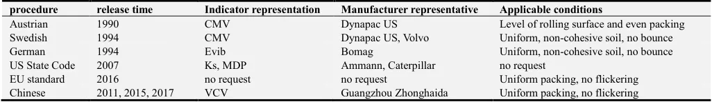
Continuous compaction equipment manufacturers in various countries (regions) selected the continuous compaction control methods and indicators widely used in the region for the typical characteristics of local packing and general engineering practice, and developed related continuous compaction control equipment [4, 8, 11-17]. The calculation method of continuous compaction control can be summarized into four categories: compaction method, modulus method, dynamic method and energy method. Various methods have proposed their own test indicators according to different calculation principles, such as compaction meter index CMV, CCV, modulus method index Evib, Ks, dynamic method index VCV, energy method index MDP. The typical compaction equipment and inspection indicators for each country (region) are shown in Table 1.
The compaction method evaluates the compaction state of the filling body by discriminating the degree of distortion of the vibration wheel response signal of the vibratory roller. Through spectrum analysis, an index that continuously evaluates the degree of waveform distortion is defined to quantitatively analyze the degree of distortion of the vibration wheel response signal. The modulus method is based on the vibration theory and the elastic half-space theory to establish a two-degree-of-freedom model of vibration compaction. Then the stiffness coefficient and dynamic modulus of the filling body are solved by the mechanical equilibrium condition to evaluate the degree of compaction. The dynamics method establishes the relationship between the vibration wheel acceleration signal and the resistance by the dynamic analysis of the interaction between the vibrating wheel and the roadbed structure of the road roller, and uses the acceleration response index as the continuous compaction test index. The energy method is based on the interaction between the vibratory roller and the ground. The concept of rolling resistance and sinking is used to determine the stress on the vibrating wheel and the energy required to overcome the resistance to evaluate the compaction of the filling body.
Table 1. Continuous compaction indicators and manufacturer representatives in each country.
procedure release time Indicator representation Manufacturer representative Applicable conditions
Austrian 1990 CMV Dynapac US Level of rolling surface and even packing
Swedish 1994 CMV Dynapac US, Volvo Uniform, non-cohesive soil, no bounce
German 1994 Evib Bomag Uniform, non-cohesive soil, no bounce
US State Code 2007 Ks, MDP Ammann, Caterpillar no request
EU standard 2016 no request no request Uniform packing, no flickering
Chinese 2011, 2015, 2017 VCV Guangzhou Zhonghaida Uniform packing, no flickering
Although the regulations and standards of various countries (regions) do not specify which methods and indicators are used, they are mostly influenced by the widespread use of compaction equipment in the country.
2.2. Quality Control Standards
The quality control standards for continuous compaction control mainly include three aspects [1, 5-10]: compaction degree, compaction uniformity and compaction stability. The degree of compaction refers to the degree to which the index of the physical and mechanical state of the laminated layer reaches the specified value during the rolling process of the filling body, which is equivalent to the concept of compaction. The degree of compaction is usually controlled by the pass rate (i.e., the ratio of the area of the passing unit to the total area of the crushed area). Compaction uniformity refers to the consistency of the distribution of physical and mechanical shapes (compacted state) of various parts on the rolling surface during the rolling process of the filling body. The compaction uniformity of the filling body has an important influence on the supporting condition of the superstructure, which is related to the performance and service life of the filling body. Compaction uniformity is often judged and evaluated by analyzing the degree of fluctuation of data at different locations after a certain pass. Compaction stability refers to the nature of the subgrade compaction state changing with the number of rolling passes during the rolling process of the filling body under the condition that the vibration compaction process parameters of the vibratory roller are constant. The stability of the compaction determines whether the filling structure can maintain a long-term stability under repeated loading. Compaction stability is usually evaluated using data rate of change for different compaction passes.
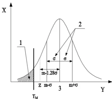
In fact, the control of compaction degree, compaction uniformity and compaction stability of the filling body is a parallel relationship, and the three are the core content of quality control and complement each other [1]. However, most countries only focus on the degree of compaction control, with compaction uniformity control as an aid. With the improvement of cognition level and the development of science and technology, compaction uniformity and compaction stability have been widely recognized. China's regulations specify specific control requirements for compaction degree, compaction uniformity and compaction stability, and propose a more comprehensive and reasonable continuous compaction quality control system. The EU regulations also emphasize compaction uniformity and compaction stability as the focus of quality control, and propose a method based on the statistical normal distribution principle (see Figure 2), which defines control based on the basic principle of normal distribution. The parameter Z = m-1.28σ, and the continuous acceptance control minimum acceptance value TM determined by calibration when the failure rate P (shaded area in Figure 2) is below a certain value. When Z ≥ TM, the requirement is met; when Z < TM, the requirement is not met. Thus, the purpose of quality assessment is achieved by specifying the failure rate. The evaluation method recommended by the EU regulations combines the degree of compaction, compaction uniformity and compaction stability for comprehensive evaluation, with
obvious advancement.
Figure 2. Schematic representation of the evaluation method based on statistical principles.
(1—The failure rate P is a function of m and σ; 2—the standard deviation σ of the vibration measurement value of the control region; 3—the average value m of the vibration measurement value of the control region; X—the vibration measurement value; Y—the probability density)
2.3. Conformity Assessment Method
The appropriate continuous compaction control quality inspection method is the key to control the quality of the filling body [8-10], and is also the core content of the continuous compaction control technical regulations. At present, the quality inspection methods for continuous compaction control adopted by various countries (regions) are generally classified into four categories: measurement calibration method, weak area identification method, measurement increment method and compaction method. Among them, the target value calibration method has been mentioned in various national standards, and it is a relatively high quality detection method [1, 5-10]; the weak area identification method is a relatively practical method [8], in real engineering. Often used more (especially in the Nordic region); compaction incremental method is usually an auxiliary method, combined with weak area identification method (such as Austrian regulations); compaction method is only suitable for small rolling area and not Important compaction control of the building, such as landfills, landscaping sites, etc. In addition, the comprehensive evaluation method proposed by the United States is a comprehensive evaluation method that summarizes and improves the above methods. The method has good applicability for different engineering application conditions.
2.3.1. Measurement Calibration Method
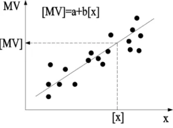
judging the applicability of the continuous compaction control index, and determining the target value of the corresponding vibration compaction measurement value according to the conventional acceptance index. The basic principle is shown in Figure 3. When the vibration measurement value is not less than the target value, the determination meets the requirement, and otherwise the determination does not satisfy the compaction requirement.
Figure 3. Target value calibration.
(X—conventional quality acceptance index value; [x]—conforming value of conventional quality acceptance index determined according to current relevant standards; MV—vibration measurement value; [MV]—vibration measurement target value; a, b—regression coefficient)
The general requirements for the quality acceptance of the national (regional) regulations using the target value calibration method are as follows: (1) The filler, water content and fill thickness of the test section are the same as those of the construction section; (2) Vibratory roller used in the test section The vibration compaction process parameters are the same as the construction section; (3) The vibratory roller is stably operated during the test, and it is strictly forbidden to use the intelligent FM amplitude modulation mode. There are certain differences in the requirements of the national regulations in the length of the test section, the corresponding conventional test indicators and quantities, and the correlation coefficient standards.
In terms of the number of conventional inspections, the basic idea of national regulations is to meet the requirements of mathematical correlation analysis under the premise of uniform distribution requirements for different detection methods. The more the number of conventional detection points, the more it reflects the average level, and the more reliable the target value is, but the engineering cost will also increase. Therefore, under the premise of meeting the engineering accuracy requirements, the national regulations comprehensively consider various factors to determine the appropriate number of conventional inspection points. In terms of correlation coefficient requirements, it is generally accepted that the correlation between the vibration measurement value and the conventional detection index is considered to be linearly related when the correlation coefficient is not less than r=0.7. At this time, continuous compaction control technology can be applied.
In addition, in terms of water content requirements, the
water content has a significant effect on the physical and mechanical properties of the filler (especially fine-grained fillers) [9-11, 18], so the national regulations mention the need to pay attention to the water content of the filler. When the water content changes greatly, on the one hand, the filler is difficult to meet the compaction requirements; on the other hand, the physical and mechanical properties of the filler correspond to the water content is not unique, that is, the filler can correspond to two different kinds under certain stiffness or compactness conditions (high, low) water content. At the same time, the sensitivity of vibration measurements to conventional water quality indicators is often quite different [9-11], resulting in a large dispersion of correlation between the two. Thus, it is difficult to meet the basic application requirements of the technology. In view of the water content of the filler, European countries have proposed that if the fine fraction (particle size <0.06 mm) exceeds 15%, special attention must be paid to the water content, but no specific standard for water content is specified. The United States attaches great importance to the water content, not only the application requirements of the filler water content in the range of 65% to 95% of the standard Platts optimum value, but also the proposed method for water content correction. Unfortunately, the US regulations are too cumbersome to control the water content of the filler, and actual engineering is often difficult to meet the requirements. China's regulations point to the need to pay attention to the problem of water content, but did not give specific recommendations and measures, still stay at the level of experience and application. It can be seen that although the influence of the water content of the filler on the continuous compaction control is significant and has been widely recognized, there is still no satisfactory application method.
2.3.2. Weak Area Identification Method
The weak area identification method is based on the vibration compaction data of all compacted areas collected by the continuous compaction control device. The data with the lowest vibration measurement value is found through the data comparison of each area, and then the pressure is realized to realize the weak area of the field and the weak area is performed. A routine quality inspection to assess the acceptance of the overall compaction quality. The method assumes that the identified weak areas are areas of lowest stiffness or density, and routine inspection and acceptance of compaction quality is performed on these areas. If the acceptance meets the requirements, the entire control area is considered to meet the requirements. The weak area identification method does not require calibration of the vibration measurement target value, and can greatly reduce the number of routine inspection acceptance tests, and is better suited for small sites or engineering situations where the target value calibration method cannot be applied.
regulations to the weak area identification method is basically the same: when the vibration measurement value is lower than a certain criterion, and the vibration measurement value is continuously lower than the specified area, it can be identified as pressure. The quality inspection of the weak areas is carried out by the conventional quality inspection method, and the overall compaction quality is evaluated according to the acceptance results of the weak areas.
2.3.3. Incremental Method of Measurement
The basic idea of the vibration measurement value increment method is that the maximum compaction degree that the filling body can achieve is also certain when the filler type, water content and process parameters are constant. Therefore, it can be judged whether the filling body has reached the compaction requirement by analyzing the change of the vibration measurement value during the continuous compaction process. When the increment of the vibration measurement value of the last two passes is less than a certain standard, it can be determined that the filling body has reached the maximum degree of compaction under the condition. The measured increment calculation is as shown in Equation 1.
-1 -1
100
i i
i
MV -MV MV
MV
∆ = × (1)
In Formula 1, MVi and MVi-1 represent measured value data of the i-th compaction and the i-th compaction, respectively. If necessary, you can use linear interpolation to convert the data onto the mesh for accurate spatial comparison. If the average value of the ∆MV array is greater than a specified value (Austria, EU regulations are 5%, Chinese regulations are 3%), it indicates that the roller compacted area may not be fully compacted and the process should be repeated. In addition, according to the standard deviation of ∆MV (usually required to have a standard deviation of not more than 10%), the repeatability of vibration measurement values can be quantified, thereby making up for the visual inspection and subjective judgment of the continuous compaction control repeatability analysis. insufficient.
The measured value increment method is better suited for situations where the target value calibration method or the packing unevenness is difficult to apply the weak area identification method, such as rock filling, non-uniform distribution of formations or fillers containing pebbles and boulders. When combined with the weak area identification method, this method can often achieve better results. The national (regional) regulations make corresponding provisions for the application of the vibration measurement value increment method, and the most critical difference is the difference in the rate of increase standard.
2.3.4. Compaction Process
The basic idea of the compaction process is that when the mechanical parameters of the compaction equipment (roller mass, vibration amplitude, vibration frequency, travel speed),
filler type, and filler moisture content are determined, the filling body can be determined according to field tests and past experience. The required fill thickness and number of compaction passes for compaction requirements. The process control of compaction is realized by an automatic positioning system and a data recording system of continuous compaction control. The key of this method is to record the process data such as the number of compaction passes and the thickness of each place in the compaction area during the real-time full-time process. It is an auxiliary acceptance method that focuses on experience and is usually applied to unimportant ones. The EU regulations allow the application of compaction processes under specific conditions, and neither the domestic nor the US regulations mention the application of this method.
2.3.5. Comprehensive Evaluation Method
Mooney and Rinehart et al. [8] presented a comprehensive evaluation method with six recommended quality assurance specifications in the NCHRP research project report. It is reported that the evaluation method has been incorporated into the upcoming US federal regulations. The six options in the comprehensive evaluation method are divided into three main categories, numbered 1, 2a, 2b, 3a, 3b and 3c. In option 1, continuous compaction control technology is used to assist quality assurance, and quality acceptance is still performed using conventional quality inspection. Options 2a and 2b are evaluations of compaction quality based on changes in vibration measurements, the basic principle of which is similar to the incremental method of measurement. Options 3a, 3b, and 3c are based on establishing a correlation between the vibration measurement value and the conventional detection relationship and performing the compaction quality by the target value obtained by the calibration. The basic principle is similar to the calibration method, but there are certain differences in the specific process of the target value rate. Each of the above options can be used as an independent method of quality assurance, or two or more options can be combined to increase the reliability of the quality assessment.
3. Conclusion
(1) The basic theory of continuous compaction control method is becoming more and more mature, and it is developing towards the theoretical direction that can truly reflect the actual vibration problem. The accuracy requirement of continuous compaction control is also gradually improved.
(2) The problem of water content of fine particle filler has a significant impact on continuous compaction control and has been widely recognized. The water content of the filler needs to be controlled in engineering applications.
(4) The quality control standard of continuous compaction control has been paid more and more attention. The comprehensive evaluation of the comprehensive evaluation of compaction degree, compaction uniformity and compaction stability is the trend of quality control standards development.
Acknowledgements
This paper is supported by the technical research topic THZQ-033-2018 of Shenzhen Construction Industry Department.
References
[1] China Railway Corporation. Q/CR 9210-2015 Technical Specification for Continuous Compaction Control of Railway Subgrade Filling Project [S]. Beijing: China Railway Publishing House, 2017.
[2] Christopher M. Savan, Kam W. Ng, Khaled Ksaibati. Benefit-cost analysis and application of intelligent compaction for transportation [J]. Transportation Geote- chnics, 2016, 9: 37–45.
[3] Manik Barman, Moeen Nazari, Syed Asif Imran, Sesh Commuri, Musharraf Zaman, Fares Beainy, Dharamveer Singh. Quality control of subgrade soil using intelli- gent compaction [J]. Innovative Infrastructure Solutions, 2016, 1 (1): 155–162.
[4] Xu Guanghui. Dynamic principle and engineering application of continuous compaction control of roadbed [M], Beijing: Science Press, 2016.
[5] Brandl, H., and D. Adam. (1997). “Sophisticated Conti- nuous Compaction Control of Soils and Granular Materials.” Proceedings 14th International Conference on Soil Mechanics and Foundation Engineering. Ham- burg, Germany, pp: 1–6.
[6] Ministry of Transport of the People's Republic of China. JT/T 1127-2017 Technical Conditions for Continuous Compaction Control System for Highway Subgrade Filling Project [S]. Beijing: China Communications Press, 2017.
[7] European Committee for Standardization. PD CEN/TS 17006:2016 Earthworks Continuous Compaction Con-trol [S]. London: BSI Standards Limited, 2017.
[8] Minnesota Department of Transportation. Mn/DOT Specification 2106 Pilot Specification for Embank- ment Grading Materials [S]. St Paul: Minnesota Depart- ment of Transportation Office of Research Services, 2007.
[9] Michael A. Mooney, Robert V. Rinehart, Norman W. Facas, et al. “Intelligent Soil Compaction Systems.” National Cooperative Highway Research Program Report 676 [R]. Washington, D. C.: Transportation Res- earch Board, 2010.
[10] Anderegg, R., K. Kaufmann. “Intelligent Compaction with Vibratory Rollers.” Transportation Research Re- cord 1868 [R]. Washington, D. C.: Transportation Resear- ch Board, 2004.
[11] Petersen, L. Continuous Compaction Control MnROAD Demonstration. Final report submitted to Mn/DOT, Report No. MN/RC-2005-07[R]. St Paul: Minnesota De- part-ment of Transportation, 2005.
[12] Forssblad L. Compaction meter on vibrating rollers for improved compaction control[C]//Proceedings of International Conference on Compaction. 1980, 2: 541– 546.
[13] Thumer H, Sandstrom A. Continuous compaction control, CCC[C]//European Workshop Compaction of Soils and Granular Materials, Presses Fonts et Chauss- ees, Paris, France. 2000: 237–246.
[14] Nohse Y, Kitano M. Development of a new type of single drum vibratory roller[C]//Proc. 14th Intl. Conf. of the Intl. Soc. For Terrain-Vehicle Systems, Vicks- burg, MS. 2002: 1–10.
[15] Mooney M A. Intelligent soil compaction systems [M]. Transportation Research Board, 2010.
[16] Anderegg, R. (1998). “Nichtlineare Schwingungen bei dynamischen Bodenver-dichtern (Nonlinear Vibrations with Dynamic Soil Compactors).” Dissertation. Diss. ETH Nr. 12419, Eidgenössische Technische Hochschule, Zürich.
[17] Anderegg, R., and K. Kaufmann. (2004). “Intelligent Compaction with Vibratory Rollers.” Transportation Research Record 1868, Transportation Research Board, Washington, D. C., pp: 124–134.