www.ijaera.org 2017, IJA-ERA - All Rights Reserved 150
Hydrodynamic Forces acting in Rectangular
Tank with and without Baffle Walls
Ashwini Dalvi1*, Prof. N. A. Maske2, Dr. S. K. Kulkarni3* 1PG student, Dept. of Civil Engineering, Dr. D. Y. Patil SOET, Pune, India
*Corresponding Author E-mail: dalvi_ashwini@ yahoo.co.in
2Assistant Professor, Dept. of Civil Engineering, Dr. D. Y. Patil SOET, Pune, India
3HOD, Dept. of Civil Engineering, Dr. D. Y. Patil SOET, Pune, India
Abstract: The failure of liquid storage tanks due to earthquake induced sloshing action of the liquid was extensively observed during past major earthquakes. Sloshing refers to the movement of liquid inside another object which is typically undergoing motion. When sloshing occurs, there will be dynamic pressure due to fluid interaction with the walls of the tank causing large deformation in the tank as well as the supporting structure. The destructive effects of sloshing can however be suppressed in a passive manner by introducing additional substructure such a baffle into tanks. The main aim of constructing these substructures is to alter the period of sloshing action beneficially and to increase hydrodynamic damping ratio. To study the sloshing effect on tank i.e. hydrodynamic forces acting on tank and to understand the response of structure under sloshing load a rectangular tank resting on ground is analyzed. The seismic parameters, base shear, hydrodynamic pressure, sloshing height is worked out in accordance with IS 1893 part 2-Criteria for Earthquake resistant design of Structure, Part 2 Liquid Retaining Tanks. An extensive literature review is carried before carrying out the above analyses to understand the methodology of analyses and the codal provisions related to the same. The base shear, hydrodynamic forces, sloshing heights for Tank with and without baffle wall is studied
Keywords: Sloshing, Baffles, Hydrodynamic dynamic pressure, Eathquake
I.INTRODUCTION
www.ijaera.org 2017, IJA-ERA - All Rights Reserved 151
A. Kumar et.al (2016) stated that perforation is one of the methods for reducing ill effects of compartmentalization. Perforation reduces pressure drop across the baffle which in turn reduces required structural strength of the baffle. Screens with optimum perforation placed appropriately may ensure greater dynamic stability without reduction in damping. Screens are widely used as damping devices in TLD in structural engineering, as Propellant Management and Acquisition Devices (PMAD) in aerospace engineering.
Finite element pressure formulation is used here to predict dynamic characteristics of bottom-mounted and surface-piercing baffles. The method is successfully extended to compute dynamic effects due to different type of perforated baffles and slat screens. Effective slosh damping, base shear force and overturning moment are computed for different type of solid and perforated baffle-mounted tanks. Effects of partially perforated baffle on dynamic response of the tank are computed for three different arrangement of perforation and optimum perforation configuration is found to achieve best dynamic advantages and reduced weight penalty without sacrificing benefits of rigidity or stiffness [5].
I.H cho et.al (2016) presented liquid sloshing inside tanks of a vessel may result in increased/decreased vessel motions or structural damages. The resonant sloshing motions can be suppressed by using baffles inside a tank. Especially, more energy dissipation is possible by using porous baffles. Here, the effect of dual vertical porous baffles on the sloshing reduction inside a rectangular tank is investigated both theoretically and experimentally. The porosity effect is included through inertial and quadratic-drag terms. The theoretical prediction is then compared with a series of experiments conducted by authors with harmonically oscillated rectangular tank at various frequencies and baffle parameters. The measured data reasonably correlate with the predicted values. It is found that the dual vertical porous baffles can significantly suppress sloshing motions when properly designed by selecting optimal porosity, submergence depth, and installation position
www.ijaera.org 2017, IJA-ERA - All Rights Reserved 152
II. SPRING MASS MODEL FOR SEISMIC ANALYSIS
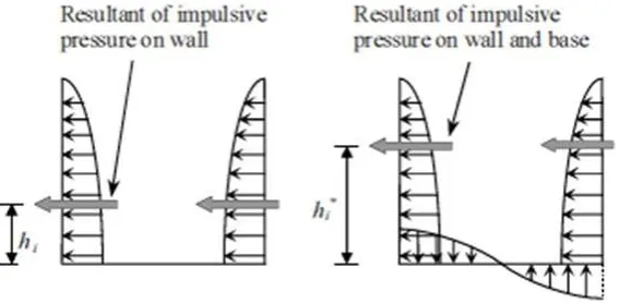
When a tank containing liquid vibrates, the liquid exerts impulsive and convective hydrodynamic pressure on the tank wall and the tank base in addition to the hydrostatic pressure. In order to include the effect of hydrodynamic pressure in the analysis, tank can be idealized by an equivalent spring mass model, which includes the effect of tank wall – liquid interaction. The parameters of this model depend on geometry of the tank and its flexibility.
When a tank containing liquid with a free surface is subjected to horizontal earthquake ground motion, tank wall and liquid are subjected to horizontal acceleration. The liquid in the lower region of tank behaves like a mass that is rigidly connected to tank wall. This mass is termed as impulsive liquid mass which accelerates along with the wall and induces impulsive hydrodynamic pressure on tank wall and similarly on base. Liquid mass in the upper region of tank undergoes sloshing motion. This mass is termed as convective liquid mass and it exerts convective hydrodynamic pressure on tank wall and base. Thus, total liquid mass gets divided into two parts, i.e., impulsive mass and convective mass.
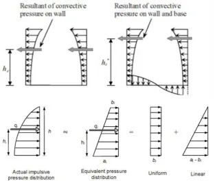
In spring mass model of tank-liquid system, these two liquid masses are to be suitably represented. A qualitative description of impulsive and convective hydrodynamic pressure distribution on tank wall and base is given in figure 2.
Tank Spring mass model
Figure 1 Spring mass model for rectangular tank
www.ijaera.org 2017, IJA-ERA - All Rights Reserved 153
Figure 3. Equivalent linear distribution along wall height Impulsive pressure
Figure 4 Equivalent linear distribution along wall height for convective pressure
Source: IS 1893 (Part2) 2014
III.METHODSANDMATERIALS
1. Objective: The purpose of this study is to study the hydrodynamic forces of rectangular tank resting on ground for tank with and without baffle wall
www.ijaera.org 2017, IJA-ERA - All Rights Reserved 154
a) Case I-Tank without Baffle
b) Case II- Tank with single baffle wall at equidistance in tank
c) Case III Tank with multiple baffle wall
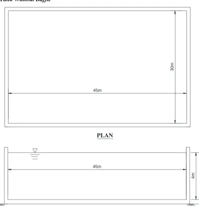
Case I- Tank Without Baffle
PLAN
SECTIONAL ELEVATION
30m
4m
45m 45m
Figure. 5. Rectangular tank sizes (not to scale)
www.ijaera.org 2017, IJA-ERA - All Rights Reserved 155
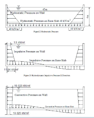
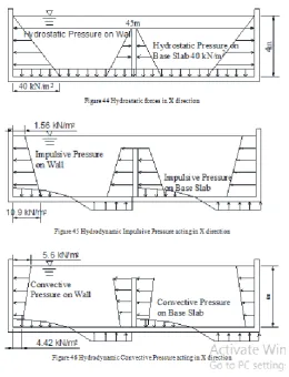
Figure 6. Hydrostatic and Hydrodynamic pressure acting in X Direction
www.ijaera.org 2017, IJA-ERA - All Rights Reserved 156
Figure 8. Total deformation of Tank without baffle wall
Case II- Rectangular tank with single baffle wall at equidistance in tank
A) Summary of Hydrostatic Pressure & hydrodynamic Pressure Acting In X Direction
www.ijaera.org 2017, IJA-ERA - All Rights Reserved 157
Figure10. Hydrostatic and Hydrodynamic pressure acting in X Direction
Figure13. Total Deformation of Tank
Case III- Rectangular tank with two baffle wall placed at equidistance
www.ijaera.org 2017, IJA-ERA - All Rights Reserved 158
Figure 11. Hydrostatic and Hydrodynamic pressure acting in X Direction
Figure12. Hydrostatic and Hydrodynamic pressure acting in X Direction
www.ijaera.org 2017, IJA-ERA - All Rights Reserved 159
mode) convective mode) mode)
Time for convective mode 15.63 sec 7.538sec 5.15sec
Base shear at bottom of
wall 3952kN 3014kN 2841kN
Equivalent Impulsive
pressure –X Direction Top=1.57kN/m2 Bottom=11.04kN/m2
Top = 1.56kN/m2
Bottom=10.9kN/m2
Top = 1.69kN/m2
Bottom=11.89kN/m2
Equivalent linear convective pressure- X Direction
Top=10.625kN/m2
Bottom=10.625kN/m2
Top=5.6 kN/m2
Bottom=4.42kN/m2 Top=3.25kN/m2
Bottom=2.55kN/m2
Sloshing Height 2.61m 1.3m 0.87m
SEISMIC FORCE IN Y DIRECTION
Sr. no Tank without Baffle Tank With Single Baffle
Wall
Tank With Double
Baffle Wall
Impulsive mass of liquid
702000kg (13% participates in Impulsive mode)
347880kg
(13% participates in convective mode)
230100kg
(13% participates in convective mode)
Convective mass of liquid
4185000kg
(78% of liquid participates in convective mode)
2073900kg
(78% of liquid mass participates in impulsive mode)
1371750kg
(78% of liquid mass participates in impulsive mode)
Time for convective mode 11.77 sec 9.61 sec 9.61sec
Base shear at bottom of
wall 4404kN
2854kN
1866
Equivalent Impulsive pressure –Y Direction
Top=1.34kN/m2
Bottom=9.4kN/m2
Top = 1.32kN/m2
Bottom=9.29kN/m2 Top = 1.34kN/m2
Bottom=9.43kN/m2
Equivalent linear convective pressure- Y Direction Top=7.25kN/m2 Bottom=6.429kN/m2 Top=7.2kN/m2 Bottom=6.4kN/m2 Top=7.25kN/m2 Bottom=6.43kN/m2
www.ijaera.org 2017, IJA-ERA - All Rights Reserved 160
V.CONCLUSIONS
In present study, tanks with and without baffle having same geometric size, seismic parameter, water height, from above calculation and analysis the following conclusion is made
• Time calculated for tanks without baffle wall is more than the time period for tanks with single baffle wall and double baffle wall. Time reduces with introduction of number of baffle walls.
• When the seismic forces act in X direction, the sloshing height calculated for tank without baffle wall is more than the sloshing height calculated for tank with baffle walls.
• When the Seismic forces acts perpendicular to baffle wall direction i.e X direction, the sloshing height reduces by introduction of additional number of baffle walls when compared to Tanks without baffle and with single baffle and so on.
• Base shear acting at bottom of wall in case of tank without baffle is more as compared to Base shear in case of tank with baffle walls.
• When the seismic force is acting in X direction, the convective pressure acting at top for Tank with Baffle is almost half of the convective pressure acting at top of Tank without baffle walls. Introduction of additional baffle walls reduces convective pressure
• The total deformation, shear stresses and normal Stress are reduced in case of tank with baffle walls
Conflict of Interest: The authors declare that they have no conflict of interest.
Ethical Statement: The authors declare that they have followed ethical responsibilities
REFERENCES
[1] Sung-Ho Yoon and Kee-Jin Park, “Effect of baffles on sloshing mitigation in liquid storage tanks,” Advanced science and technology (2015).
[2] Mahmood Hosseini, Hamidreza Vosoughifar , Pegah Farshadmanesh ,“Simplified dynamic analysis of sloshing in rectangular tanks with multiple vertical baffle”, Journal of Water sciences research, Vol.5, No.1(2012).
[3] M.F.Younes, Y.K.Younes, “Experimental investigation for liquid sloshing in baffled rectangular tanks, International journal of scientific & technology research volume 4, issue 12, december (2015).
[4] Mohammad Ali Goudarzian, Pouya Nourae Danesh, “Numerical investigation of a vertically baffled rectangular tank under seismic excitation”, Journal of fluids and structures (2016).
[5] Kumar, K.P. Sinhamahapat Dynamics of rectangular tank with perforated vertical baffle Ocean engineering (2015).
[6] I.H. Choa, M.H.Ki, “Effect of dual vertical porous baffles on sloshing reduction in a swaying rectangular tank”, Ocean engineering (2016).
[7] M.F.Younes, Y.K.Younes “Experimental investigation for liquid sloshing in baffled rectangular tanks”, International journal of scientific & technology research volume 4, issue 12, december (2015).
[8] J.H. Jung, H.S. Yoon, C.Y. Lee, S.C.Shin “Effect of the vertical baffle height on the liquid sloshing in a three-dimensional rectangular tank ,”Ocean engineering (2012).