International Journal of Science Engineering and Advance Technology,
IJSEAT, Vol 2, Issue 9, September - 2014
ISSN 2321-6905
www.ijseat.com Page 376
A Novel Strategy for Static Compensator Based Control of Grid
Interfaced OWF and MCF for Dynamic Stability Enhancement
SUBODH KUMAR CH
P.G. scholar, Dept of EEE Trr College of Engineering & Technology,Hyderabad, Telangana, India
BHARGAV RAM T
Associate
professor, Dept of EEE Trr College of Engineering & Technology,Hyderabad, Telangana, India
Abstract— This paper presents a novel strategy for static compensator based control of grid interfaced OWF and MCF for dynamic stability enhancement. The performance of the studied OWF is simulated by an equivalent doubly-fed induction generator (DFIG) driven by an equivalent wind turbine (WT) while MCF is simulated by an equivalent squirrel-cage rotor induction generator (SCIG). A PID controller for the STATCOM is proposed to contribute effective damping characteristics to the studied system under different operating conditions. The model studied is subject to various disturbances, like noise wind speed disturbance, marine current speed disturbance and a three phase short circuit fault at grid. It can be concluded from the simulated results that the proposed STATCOM is very effective to stabilize the studied system under disturbance conditions. The voltage fluctuations of the AC bus subject to the active-power variations of the studied system can also be effectively controlled by the proposed control scheme, MATLAB/SIMULINK results verified the effectiveness of proposed control scheme.
I. I
NTRODUCTIONThe wind energy and ocean energy have been integrated together in the U. K. [1]. Ocean energy may include tidal energy, wave energy, thermal energy, offshore wind energy. Offshore generators driven by wind turbine (WT) combined with generators driven by marine-current turbine (MCT) will become hybrid scheme for energy production in future. Since oceans cover more than 70% surface of the earth, this hybrid scheme can be extensively developed at different parts of the world in future. One of the method of running OWF is to connect the output terminals of DFIGs together and then connect to power grid through an offshore step-up transformer and undersea cables. To run an MCF we may use squirrel-cage induction generators (SCIG) connected to power grid through an offshore step-up transformer and undersea cables. The WT and MCT have same operating characteristics.
The OWF with DFIG operate at close to unity power factor, while MCF with SCIG requires reactive power for magnetization. When the generated active power of an DFIG based OWF is varied due to noise wind speed disturbance, the active power generated by MCF is affected, the reactive power generated by OWF and MCF is also affected, the common AC bus voltage also affected. In the event of marine-current fluctuations the absorbed and generated active power also affected and grid disturbances
like faults at grid, an energy storage system or a control device for a large-scale high-capacity power generation system is generally required to compensate fluctuating components when connected to a power grid. A large scale OWF may combine with different FACTS devices or energy-storage systems such as STATCOM [2], super conducting magnetic energy storage system (SMES) [3] etc.
The analyzed results of stability improvement of power systems using STATCOMs and the damping controller design of STATCOMs were presented in [4]. The design of an output feed-back linear quadratic controller for a STATCOM and a variable-blade pitch of a wind energy conservation system to perform both voltage control and mechanical power control under grid-connection or islanding conditions were shown in [5]. System modeling and controller design for fast load voltage regulation and mitigation of voltage flicker using a STATCOM were demonstrated in [6]. A new D-STATCOM control algorithm enabling separate control of positive and negative sequence currents was proposed, and the algorithm was based on the developed mathematical model in the co-ordinates for a D-STATCOM operating under unbalanced conditions [7].
International Journal of Science Engineering and Advance Technology,
IJSEAT, Vol 2, Issue 9, September - 2014
ISSN 2321-6905
www.ijseat.com Page 377
improvement of dynamic and transient stability and transmission capability. The performance of the different FACTS/BESS combinations was compared and provided experimental verification of the proposed controls on a scaled STATCOM/BESS system.
II. INTEGRATED
OWF
ANDMCF MODELS
Fig.1 shows the configuration of the studied integrated DFIG-based OWF and SCIG-based MCF with the proposed STATCOM. The80-MW OWF is represented by a large equivalent aggregated DFIG driven by an equivalent aggregated variable-speed WT through an equivalent aggregated gear box. The 40-MW MCF is represented by a large equivalent aggregated SCIG driven by an equivalent aggregated variable-speed MCT through an equivalent aggregated gear-box. The OWF the MCF, the STATCOM and a local load are connected to an AC bus that is fed to the on shore power grid through an offshore step-up transformer and under sea cables. The employed mathematical models of the studied system are described as below.
A. Wind Turbine
The mechanical power (in W) produced by a WT can be expressed by
Pmw= ρw. Arw. Vw3. Cpw(λw, βw) (1)
Where
ρwis the air density in Kg/m 3, Arwis the blade impact area in m2, Vwis the wind speed in m/s , and Cpwis the power coefficient in m/s of the WT . The wind speed Vwis modeled as the algebraic sum of a base wind speed, a gust wind speed, a ramp wind speed and a noise wind speed. The detailed equations for these four wind speed components can be referred to [15] while the power coefficient of the WT is given by [16].
The cut-in, rated, and cut-out wind speeds of the studied WT are 4, 15, and 24 m/s, respectively. When Vwis lower than the rated wind speed of the WT (Vwrated), βw= 00. When Vw>Vwrated, the pitch angle control system of the
WT ( βw) increases. Fig. 3. shows the characteristics of the captured per-unit mechanical power versus the per-unit generator rotor speed of one of the forty 2-MW WTs of the studied 80-MW OWF from cut-in wind speed to rated wind speed. The optimal output points in Fig.3 are the ideal maximum output mechanical power of the WT.
B. Mass-Spring-Damper system and Induction Generator
Fig. 4 shows the two-inertia reduced-order equivalent mass-spring-damper model of the WT coupled to the rotor shaft of the studied wind DFIG [17]-[19].The effect of the equivalent gear box (GBw) between the WT and DFIG has been included in this model.
Fig.1. Configuration of the integrated OWF and MCF with STATCOM.
Fig.2. Block diagram of the pitch-angle control system of the studied WT.
Fig.3. Characteristics of turbine power versus generator rotor speed.
Fig.4. Two-inertia reduced-order equivalent mass-spring-damper model of the WT coupled to the rotor shaft of the
studied wind DFIG.
International Journal of Science Engineering and Advance Technology,
IJSEAT, Vol 2, Issue 9, September - 2014
ISSN 2321-6905
www.ijseat.com Page 377
improvement of dynamic and transient stability and transmission capability. The performance of the different FACTS/BESS combinations was compared and provided experimental verification of the proposed controls on a scaled STATCOM/BESS system.
II. INTEGRATED
OWF
ANDMCF MODELS
Fig.1 shows the configuration of the studied integrated DFIG-based OWF and SCIG-based MCF with the proposed STATCOM. The80-MW OWF is represented by a large equivalent aggregated DFIG driven by an equivalent aggregated variable-speed WT through an equivalent aggregated gear box. The 40-MW MCF is represented by a large equivalent aggregated SCIG driven by an equivalent aggregated variable-speed MCT through an equivalent aggregated gear-box. The OWF the MCF, the STATCOM and a local load are connected to an AC bus that is fed to the on shore power grid through an offshore step-up transformer and under sea cables. The employed mathematical models of the studied system are described as below.
A. Wind Turbine
The mechanical power (in W) produced by a WT can be expressed by
Pmw= ρw. Arw. Vw3. Cpw(λw, βw) (1)
Where
ρwis the air density in Kg/m 3, Arwis the blade impact area in m2, Vwis the wind speed in m/s , and Cpwis the power coefficient in m/s of the WT . The wind speed Vwis modeled as the algebraic sum of a base wind speed, a gust wind speed, a ramp wind speed and a noise wind speed. The detailed equations for these four wind speed components can be referred to [15] while the power coefficient of the WT is given by [16].
The cut-in, rated, and cut-out wind speeds of the studied WT are 4, 15, and 24 m/s, respectively. When Vwis lower than the rated wind speed of the WT (Vwrated), βw= 00. When Vw>Vwrated, the pitch angle control system of the
WT ( βw) increases. Fig. 3. shows the characteristics of the captured per-unit mechanical power versus the per-unit generator rotor speed of one of the forty 2-MW WTs of the studied 80-MW OWF from cut-in wind speed to rated wind speed. The optimal output points in Fig.3 are the ideal maximum output mechanical power of the WT.
B. Mass-Spring-Damper system and Induction Generator
Fig. 4 shows the two-inertia reduced-order equivalent mass-spring-damper model of the WT coupled to the rotor shaft of the studied wind DFIG [17]-[19].The effect of the equivalent gear box (GBw) between the WT and DFIG has been included in this model.
Fig.1. Configuration of the integrated OWF and MCF with STATCOM.
Fig.2. Block diagram of the pitch-angle control system of the studied WT.
Fig.3. Characteristics of turbine power versus generator rotor speed.
Fig.4. Two-inertia reduced-order equivalent mass-spring-damper model of the WT coupled to the rotor shaft of the
International Journal of Science Engineering and Advance Technology,
IJSEAT, Vol 2, Issue 9, September - 2014
ISSN 2321-6905
www.ijseat.com Page 378
The per-unit q- and d-axis voltage - current equations of an induction generator can be referred to [26] and they can be used for the electrical parts of the wind DFIG and the marine-current SCIG.
C. Power Converters of DFIG
Fig.5 shows the one-line diagram of the studied wind DFIG. The stator windings of the wind DFIG are directly connected to the low-voltage side of the 0.69/23-kv step-up transformer while the rotor windings of the DFIG are connected to the same 0.69-kv side through a rotor-side converter (RSC), a DC link, a grid-side converter (GSC), a step-up transformer,, and a connection line.
Fig. 5. One-line diagram of the studied doubly-fed induction generator.
Fig. 6. Control block diagram for the RSC of the DFIG
For normal operation of a wind DFIG, the input AC-side voltages of the RSC and the GSC can be effectively controlled to achieve the aims of simultaneous output active-power and reactive-power control. Fig.6 shows the control block diagram of the RSC of the studied DFIG. As shown in Fig. 6, the operation of the RSC requires iqrwand idrw to follow the varying reference points that are determined by maintaining the output active power and the stator-winding voltage at the setting values, respectively. The required voltage for the RSC (Vrw) is derived by controlling the per-unit q- and d-axis currents of the RSC [21]-[23]. The control block diagram of the GSC of the studied wind DFIG is shown in Fig. 7. The per unit q- and d-axis currents of the GSC, iqgw and idgw , have to track the reference points that are determined by maintaining the DC link voltage Vdcwat the setting value and keeping the output of the GSC at unity power factor,
respectively. The required per-unit voltage of the GSC (vgw ) is derived by controlling the per-unit q- and d-axis currents of the GSC [21]-[23].
Fig. 7. Control block diagram for the GSC of the DFIG.
D. Marine-Current Speed and Marine-Current Turbine
The MCT is assumed to be driven by tide velocities, and the current velocity is determined by spring and neap tides. The marine-current speeds are given at hourly intervals starting at 6 h before high waters and ending 6 h after. It is easy to derive a simple and practical model for marine-current speeds under the knowing tide coefficients as follows:
VMR= Vnt+
( )( )
(2)
Where Cmr is the marine coefficient, 95 and 45 are the spring and neap tide medium coefficients, respectively, and Vstand Vntare the spring and neap marine-current speeds, respectively [1]. The employed marine-current model is between France to England area [1]. The mechanical power (in W) generated by the studied MCT can be expressed by
Pmmr= ½ ρmr.Armr .V3MR. Cpmr(λmr, βmr) (3)
Where ρmris the seawater density in kg/m3(ρmr= 1025 kg/m3), Armr is the blade impact area in m
2
, VMRis the marine velocity in m/s as depicted in (2), and Cpmris the power coefficient of the MCT.
The cut-in, rated and cut-out speeds of the studied MCT are 1, 2.5, and 4 m/s, respectively. When VMRis higher than the rated speed, the pitch-angle control system of the MCT activates to limit the output power of the MCT at the rated value. Since the employed turbine model, pitch-angle control system, and mass-spring-damper model of the studied MCF are similar to the ones that are employed in the OWF, some mathematical models employed in the OWF can be slightly modified to be used in the MCF except the parameters.
E. STATCOM
The one-line diagram of the studied STATCOM was shown in Fig. 1. The per-unit q- and d-axis output voltages of STATCOM can be expressed by, respectively, [11]
Vqsta= Vdcsta.km .cos( θbus+ α ) (4)
International Journal of Science Engineering and Advance Technology,
IJSEAT, Vol 2, Issue 9, September - 2014
ISSN 2321-6905
www.ijseat.com Page 378
The per-unit q- and d-axis voltage - current equations of an induction generator can be referred to [26] and they can be used for the electrical parts of the wind DFIG and the marine-current SCIG.
C. Power Converters of DFIG
Fig.5 shows the one-line diagram of the studied wind DFIG. The stator windings of the wind DFIG are directly connected to the low-voltage side of the 0.69/23-kv step-up transformer while the rotor windings of the DFIG are connected to the same 0.69-kv side through a rotor-side converter (RSC), a DC link, a grid-side converter (GSC), a step-up transformer,, and a connection line.
Fig. 5. One-line diagram of the studied doubly-fed induction generator.
Fig. 6. Control block diagram for the RSC of the DFIG
For normal operation of a wind DFIG, the input AC-side voltages of the RSC and the GSC can be effectively controlled to achieve the aims of simultaneous output active-power and reactive-power control. Fig.6 shows the control block diagram of the RSC of the studied DFIG. As shown in Fig. 6, the operation of the RSC requires iqrwand idrw to follow the varying reference points that are determined by maintaining the output active power and the stator-winding voltage at the setting values, respectively. The required voltage for the RSC (Vrw) is derived by controlling the per-unit q- and d-axis currents of the RSC [21]-[23]. The control block diagram of the GSC of the studied wind DFIG is shown in Fig. 7. The per unit q- and d-axis currents of the GSC, iqgwand idgw, have to track the reference points that are determined by maintaining the DC link voltage Vdcwat the setting value and keeping the output of the GSC at unity power factor,
respectively. The required per-unit voltage of the GSC (vgw ) is derived by controlling the per-unit q- and d-axis currents of the GSC [21]-[23].
Fig. 7. Control block diagram for the GSC of the DFIG.
D. Marine-Current Speed and Marine-Current Turbine
The MCT is assumed to be driven by tide velocities, and the current velocity is determined by spring and neap tides. The marine-current speeds are given at hourly intervals starting at 6 h before high waters and ending 6 h after. It is easy to derive a simple and practical model for marine-current speeds under the knowing tide coefficients as follows:
VMR= Vnt+
( )( )
(2)
Where Cmr is the marine coefficient, 95 and 45 are the spring and neap tide medium coefficients, respectively, and Vstand Vntare the spring and neap marine-current speeds, respectively [1]. The employed marine-current model is between France to England area [1]. The mechanical power (in W) generated by the studied MCT can be expressed by
Pmmr= ½ ρmr.Armr .V3MR. Cpmr(λmr, βmr) (3)
Where ρmris the seawater density in kg/m3(ρmr= 1025 kg/m3), Armr is the blade impact area in m
2
, VMRis the marine velocity in m/s as depicted in (2), and Cpmr is the power coefficient of the MCT.
The cut-in, rated and cut-out speeds of the studied MCT are 1, 2.5, and 4 m/s, respectively. When VMRis higher than the rated speed, the pitch-angle control system of the MCT activates to limit the output power of the MCT at the rated value. Since the employed turbine model, pitch-angle control system, and mass-spring-damper model of the studied MCF are similar to the ones that are employed in the OWF, some mathematical models employed in the OWF can be slightly modified to be used in the MCF except the parameters.
E. STATCOM
The one-line diagram of the studied STATCOM was shown in Fig. 1. The per-unit q- and d-axis output voltages of STATCOM can be expressed by, respectively, [11]
International Journal of Science Engineering and Advance Technology,
IJSEAT, Vol 2, Issue 9, September - 2014
ISSN 2321-6905
www.ijseat.com Page 379
Vdsta=Vdcsta.km .sin( θbus+ α ) (5)
Where Vqstaand Vdstaare the per-unit q- and d-axis voltages
at the output terminals of the STATCOM, respectively, θbus is the phase angle of the AC-bus voltage, Vdcstais the per-unit DC voltage of the DC capacitor Cm, and km and α are the modulation index and phase angle of the STATCOM, respectively. The per-unit DC voltage-current equation of the DC equivalent capacitance Cm can be written as
( Cm) (Vdcsta) = ωb[ Idcsta–( Vdcsta/ Rm)] (6) Where
Idcsta= iqsta.km .cos( θbus+ α ) + idsta. km .sin( θbus+ α ) (7) is the per-unit DC current flowing into the positive terminal of Vdcsta , Rm is the per-unit equivalent resistance that considers the equivalent electrical losses of the STATCOM, and iqstaand idstaare the per-unit q- and d-axis currents flowing into the terminals of the STATCOM, respectively. The control block diagram of the proposed STATCOM including the proposed STATCOM including a damping controller is shown in Fig. 8. The per-unit DC voltage Vdcstaiscontrolled by the phase angle α while the voltage Vstais varied by changing the modulation index km. The employed parameters of this paper are listed in Table I.
Fig. 8. Control block diagram of the proposed STATCOM including the PID damping controller.
III. SIMULATION
RESULTS
This section uses the nonlinear system model developed in Section II to compare the damping characteristics contributed by the proposed STATCOM joined with PID damping controller on dynamic stability improvement of the studied system under a noise wind-speed disturbance, a marine-current speed disturbance, and a three-phase short-circuit fault at the grid, respectively.
A. Noise Wind-Speed Disturbance
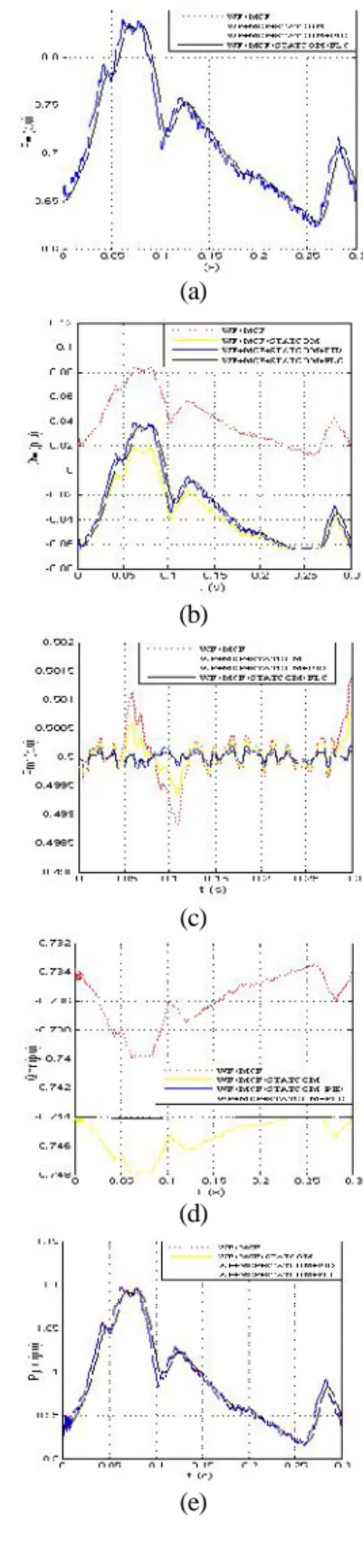
The noise wind-speed disturbance shown in Fig. 10(h) is added to studied system, but the marine-current speed is still kept at Vmr= 2.5 m/s. Fig 10(a)-(g) illustrates the studied system with and without the STATCOM and the designed PID damping controller under the noise wind-speed disturbance.
(a)
(b)
(c)
(d)
International Journal of Science Engineering and Advance Technology,
IJSEAT, Vol 2, Issue 9, September - 2014
ISSN 2321-6905
www.ijseat.com Page 380
(f)
(g)
Fig. 10. Dynamic response of the studied system with and without PID STATCOM damping controller under noise wind speed disturbance (a) Pw,(b) Qw,(c) Pmr,(d) Qmr, (e)
Pgrid, (f) Vbus, (g) Vw.
The dynamic simulation results shown in Fig. 10(a)-(g) are analyzed as below.
1) It can be seen that STATCOM can effectively maintain the AC bus voltage at 1.0 p.u by properly
adjusting αto tune the quality of the reactive power of the STATCOM delivered to the AC bus and fluctuations of active and reactive power are minimized.
2) STATCOM can offer adequate damping characteristics to the studied system, the oscillations of Pw , Qw , Pmr, Qmr Pgrid , Qgrid and Vbus due to random noise wind speed disturbance can be fast damped .
3) The Pmr, Qmrand Vbus have the smallest amplitudes in three curves with PID controller.
4) The generated active power DFIG Pwshown in fig 10(a) is not affected by the addition of STATCOM with PID controller.
B. Marine-Current Speed Disturbance
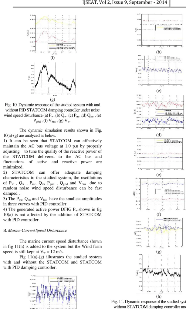
The marine current speed disturbance shown in fig 11(h) is added to the system but the Wind farm speed is still kept at Vw= 12 m/s.
Fig 11(a)-(g) illustrates the studied system with and without the STATCOM and STATCOM with PID damping controller.
(a)
(b)
(c)
(d)
(e)
(f)
(g)
(h)
Fig. 11. Dynamic response of the studied system with and without STATCOM damping controller under marine-current speed disturbance (a) Pw,(b) Qw,(c) Pmr,(d) Qmr
International Journal of Science Engineering and Advance Technology,
IJSEAT, Vol 2, Issue 9, September - 2014
ISSN 2321-6905
www.ijseat.com Page 381
It is observed from simulations that all quantities are slightly deviated from steady state operating points at t = 0 s due to small variations of marine current speed.
Since marine-current speed is closely related to the output active power of the MCT, it is seen that the response of Pmr shown in Fig. 11(c) is similar to the one of Vmr shown in Fig. 11(h) and the high-frequency components existing in shown in Fig. 6.2(h) have been filtered out. Comparing the dynamic responses of Qmr shown in Fig. 11(d) with Vmr shown in Fig. 11(h), it is found that the magnitude of Qmr gets higher when Vmrincreases This is due to the fact that the IG-based MCF requires larger reactive power for magnetization when the rotational speed and the output active power of the SCIG of the MCF increase. The system has better damping and peak magnitude of oscillations are minimum with the proposed scheme.
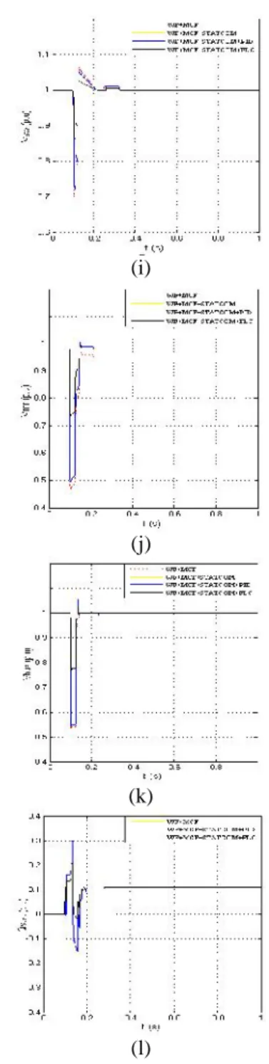
C. Three-Phase Short-circuit Fault at Power Grid
The OWF operates under a base wind speed of Vw = 12 m/s and MCF operates under a base marine current speed of Vmr= 2.5 m/s. A three phase short circuit fault is applied to the grid at t = 0.1 s and cleared at t = 0.125 s.
It is seen when fault is applied all the values drop to low values and when fault is cleared all the responses stably return to the original steady-state operating conditions. The STATCOM can offer better damping characteristics to the studied system. The peak magnitude of oscillation reached is minimum with STATCOM.
(a)
(b)
(c)
(d)
(e)
(f)
(g)
International Journal of Science Engineering and Advance Technology,
IJSEAT, Vol 2, Issue 9, September - 2014
ISSN 2321-6905
www.ijseat.com Page 382
(i)
(j)
(k)
(l)
Fig. 12. Transient response of the studied system with and without STATCOM damping controller under three-phase fault at power grid (a) Pw, (b) Qw, (c) Pmr, (d) Qmr, (e) Pgrid, (f) Qgrid, (g) Wgw, (h) Wgmr, (i) Vsw,(j) Vmr, (k) Vbus, (l)
Vw.
IV. CONCLUSION
This paper presented the enhancement and stability improvement of an integrated OWF and MCF using STATCOM. Time domain simulations are carried out for the studied system. The studied system is subjected to a noise wind-speed disturbance, a marine-current speed disturbance a three phase short circuit fault at the grid have been systematically performed to demonstrate the
effectiveness of proposed controller for STATCOM on suppressing fluctuating active and reactive powers of the studied system and improving the dynamic stability and transient stability under different operating conditions. It can be concluded from simulated results that the proposed STATCOM is capable of improving the performance of the studied integrated OWF and MCF under variable situations.
REFERENCES
[1] S. E. B. Elghali , R. Balme , K. L. Saux , M. E. H. Benbouzid , J. F. Charpentier and F. Hauville "A simulation model for the evaluation of the electrical power potential harnessed by a marine current turbine", IEEE J. Ocean. Eng., vol. 32, no. 4, pp.786 -797, Oct. 2007.
[2] H. Chong, A. Q. Huang, M. E. Baran, S. Bhattacharya, W. Litzenberger, L. Anderson, A. L.
Johnson, and A. A. Edris, “STATCOM impact study
on the integration of a large wind farm into a weak
loop power system,” IEEE Trans. Energy Convers., vol. 23, no. 1, pp. 226–233, Mar. 2008.
[3] H. Gaztanaga , I. Etxeberria-Otadui , D. Ocnasu and S. Bacha "Real-time analysis of the transient response improvement of fixed-speed wind farms by using a reduced-scale STATCOM prototype", IEEE Trans. Power Syst., vol. 22, no. 2, pp.658 -666,May2007.
[4] K. R. Padiyar and N. Prabhu, “Design and
performance evaluation of sub synchronous damping
controller with STATCOM,” IEEE Trans. Power Del., vol. 21, no. 3, pp. 1398–1405, Jul. 2006. [5] W. L. Chen and Y. Y. Hsu "Controller design for an induction generator driven by a variable-speed wind turbine", IEEE Trans. Energy Convers., vol. 21, no. 3, pp.635 -625, Sep. 2006.
[6] A. Jain , K. Joshi , A. Behal and N. Mohan "Voltage regulation with STATCOMs: Modeling, control and results", IEEE Trans. Power Del., vol. 21, no. 2, pp.726 -735, Apr. 2006.
[7] B. Blazic and I. Papic "Improved D-STATCOM control for operation with unbalanced currents and voltages", IEEE Trans. Power Del., vol. 21, no. 1, pp.225 -233, Jan. 2006.
[8] A. H. Norouzi and A. M. Sharaf "Two control schemes to enhance the dynamic performance of the STATCOM and SSSC", IEEE Trans. Power Del., vol. 20, no. 1, pp.435 -442,Jan. 2005.
[9] K. V. Patil , J. Senthil , J. Jiang and R. M. Mathur "Application of STATCOM for damping torsinal oscillations in series compensated AC system", IEEE Trans. Energy Convers., vol. 13, no. 3, pp.237 -243,Sep. 1998.
International Journal of Science Engineering and Advance Technology,
IJSEAT, Vol 2, Issue 9, September - 2014
ISSN 2321-6905
www.ijseat.com Page 383
[11] P. Rao , M. L. Crow and Z. Yang "STATCOM control for power system voltage control applications", IEEE Trans. Power Del., vol. 15, no. 4, pp.1311 -1317,Oct. 2000.
[12] Y. Ye , M. Kazerani and V. H. Quintana "Current-source converter based STATCOM: Modeling and control", IEEE Trans. Power Del., vol. 20, no. 2, pp.795 -800 ,Apr. 2005.
[13] Z. Yang , C. Shen , L. Zhang , M. L. Crow and S. Atcitty "Integration of a STATCOM and battery energy storage", IEEE Trans. Power Syst., vol. 16, no. 2, pp.254 -260, May. 2001.
[14] R. Griinbanm , P. Halvarsson , D. Larsson and P. R. Jones "Conditioning of power grids serving offshore wind farms based on asynchronous generator", Proc. Conf. Power Electronics, Machine and Drives, vol. 1, pp.34 -39 Mar./Apr.2004. [15] P. M. Anderson and A. Bose "Stability simulation of wind turbine system", IEEE Trans. Power App. Syst., vol. PAS-102, pp.3791 -3795, Dec.1983.
SUBODH KUMAR CH currently pursuing his M.Tech in Electrical Power Systems from TRR Engineering College, Hyderabad, Telangana, India affiliated to JNTU University, Hyderabad. He has done his B.Tech degree from Gnyana Saraswathi College of Engineering & Technology, affiliated to JNT University, Hyderabad, Telangana, India and his fields of interest include Non Conventional Energy Sources and Power Systems.