* To whom all correspondence should be addressed.
Production of the Electric Vehicle Experimental
Prototype with the Range Extender
Sergey Vasilievich Bakhmutov1, Kirill Evgenievich Karpukhin2, Alexey Stanislavovich Terenchenko3, Rinat Hanyafievich Kurmaev 4, Vladimir Nikolaevich Kondrashov 5 and Sergey Feliksovich Sklyarinskii6
1Deputy CEO for Science, Doctor of Science, Professor, 2Head of Department, Doctor of Philosophy, 3Director of Centre, Doctor of Philosophy, 4Head of Department, Doctor of Philosophy, Associate
of Professor, 5Head of Department, 6Head of the Sector,
Federal State Unitary Enterprise Central Scientific Research Automobile and Automotive Institute “NAMI” (FSUE «NAMI»), Avtomotornaya street, 2, Moscow, Russia, 125438.
doi: http://dx.doi.org/10.13005/bbra/2230 (Received: 01 June 2015; accepted: 10 August 2015)
This paper proves the expediency of the vehicle developmental prototype use with a Range Extender unit and touches upon its production. It contains layout solutions for mounting of the engine-generator unit, thermostatting systems and electric energy storage of the vehicle, as well as describes in details the developed principal scheme of the liquid cooling system.
Key words: Experimental prototype, Electric vehicle, Hybrid vehicle, Combined power unit, Range Extender, Electric energy Accumulation and storage system, Thermostatting system.
Ecological cleanliness and fuel efficiency of vehicles become a key problem of development of modern automotive industry. Large amount of developed countries introduce government programs on development of non-polluting and efficient transport. There is an increasing demand for effective and non-polluting vehicles. As a rule, such vehicles have an electric drive. Such vehicles include electromobiles and hybrid vehicles (Bakhmutov and Karpukhin, 2012, Zvonov et al.,
2001, Luksho et al., 2015).
Today a competitive and comparatively non-polluting vehicle may be designed following the scheme of a hybrid power unit, which includes
an internal combustion engine, an electric engine, a voltage converter and an energy storage unit (accumulator batteries of various electrochemical systems, supercondensers, hydrogen fuel cells, etc.)3.
Research proves technical and economic expediency of creation of the vehicle with the combined power unit, which is more ecologically friendly and 5-10 % more efficient than the vehicle with an ICE.
The main part
The State Research Center of Russian Federation FSUE “NAMI” conducts applied scientific researches on the topic “Development of the combined power unit in vehicles with algorithms of interaction of the basic elements, providing enhancement of their total power efficiency”.
taken as a basic model for designing a vehicle with the combined power unit.
This is a small class vehicle developed on the basis of a serial model of VAZ 1117 KALINA, with the station wagon body type. As the traction engine, this vehicle has an asynchronous electric machine with the liquid cooling, located in an engine compartment in the front part of a body, transversely to the longitudinal axle of the vehicle. The front traction wheels drive is performed by electric machine via the two-stage cylindrical constant mesh reducer which is the final drive with rigid kinematic connection via a differential with traction wheels’ hubs by means of two drive shafts
of different length with constant velocity joints on both sides for maintenance of combined work of a drive, a suspension and steering control. (Terenchenko et al., 2015, Kurmaev et al., 2015, Shorin et al., 2013).
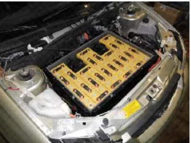
Units of suspension, steering control, brake control are identical to that of the basic VAZ 1117 KALINA vehicle. As a traction accumulator battery, the blocks of accumulator cells located in front and rear parts of a body were used. The first block of accumulator cells (Picture 2à) is located in the engine compartment, directly above the traction electric machine in the special case made of sheet metal.
The second block is in the special niche in a body floor, located under a rear passenger seat. The third block is also located in the special niche behind a rear passenger seat, in front of a spare wheel compartment. The position of the second and third blocks of accumulator cells is shown in the Picture 2b.
An engine-generator unit increasing the electric vehicles driving range without rigid kinematic connection with the vehicles driving axle and globally known as the “Range Extender” was
Fig.1. Electromobile VAZ 1817 ELLADA
Fig.2. a) the first block of accumulator cells; b) position of the second and the third blocks of accumulator cells
used as a combined power unit on this vehicle. Due to the fact that development of Range Extender units is one of the promising directions of the automotive industry development, works on creation and further improvement of these units are actively conducted in many economically developed countries, such as USA, Germany, UK, France etc. (Andert et. al., 2012, Noga,. 2013, Gage and Bogdanoff, 1997). This unit consists of an internal combustion engine having a small operating volume and an electric machine operating in a generator mode. Examples of such units are shown in the Picture 3.
One of the advantages of this unit is its’ small overall dimensions, allowing to use different variants of its configuration on the chassis of small class electric vehicles.
The DSM200300-S 6L04Y model was chosen on the basis of the data obtained when performing a calculation and as a result of the conducted analysis of market offers on the engine generator units. The supplier of the engine -generator unit is DSM Green Powår Co. This unit comprises an engine QR372 and a generator 20 kW/270V. Overall dimensions of this unit are shown in the Picture 4.
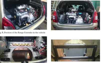
The engine-generator unit has a transverse position in a trunk of the vehicle’s body on a place of the removed compartment for spare wheel storage (Picture 5).
It is mounted on a special sub-frame that is fixed with four elasto-kinematic supports to the load-bearing elements of the rear part of the vehicle’s body (Picture 6).
The unit is separated from the vehicle’s interior by the special partitions equipped with thermal insulation materials.
The electric energy storage system with thermostatting system (Picture 7) was developed for the experimental prototype of the vehicle with the Range Extender unit. Picture 7 – the electric energy accumulation and storage system with thermostatting system (1 – case of accumulator batteries; 2 – lithium-ion cell Winston LYP90AHA; 3 – copper junction plate; 4 – radial fan SPAL VA32 - À100-62S; 5 – Peltier element). (Slabosritsky et al., 2011; Slabosritsky et al., 2012, Slabosritsky et al., 2013, Kim and Pesaran, 2006, Pesaran, 2001).
The following preparation works were conducted before installation of the electric energy storage system with a system of thermostatting of electrical energy storage units for the vehicle’s
Fig. 4. Engine-generator unit DSM200300-S 6L04Y and its overall dimensions.
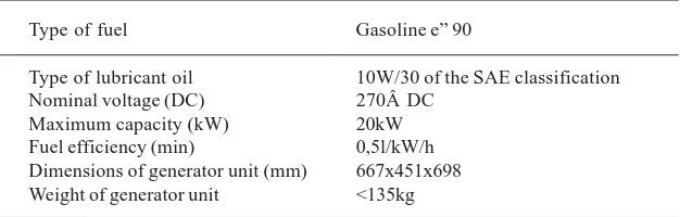
Table 1. Technical specifications of the engine-generator unit DSM200300-S 6L04Y
Type of fuel Gasoline e” 90
Type of lubricant oil 10W/30 of the SAE classification Nominal voltage (DC) 270Â DC
combined power units under development: • The system of the vehicle cooling is adapted, liquid lines are laid on a new trajectory; • The vehicle’s electric wiring is adapted, high-voltage wires are laid in new directions, their length and system of fixation are modified as well. The overall view of the underhood space with the developed electric energy storage system is shown in the Picture 8.
The principal diagramme of liquid cooling system was developed for the Range Extender system within the vehicle6, 7. The overal view of
the principal diagramme of the liquid cooling system is shown on the Picture 9.
The distinctive feature of this system is the presence of two independent cooling circuits. The first circuit consists of a cooling subcircuit of the Range Extender unit and a cooling subcircuit of the electric machine.
Structure of the first circuit includes:
• A liquid-air radiator with a fan, providing drop of thermal emissions from an ICE and an electric machine;
• An electric liquid pump providing the constant coolant flow through components; • Three taps with remote adjustment of the coolant flow productivity;
Fig. 5. Position of the Range Extender in the vehicle
Fig. 6. Mounting of the subframe to the load-bearing elements of the body
• An expansion tank.
The second circuit consists of a cooling subcircuit of the inverter and a cooling subcircuit of the onboard charger. Such system provides maintenance of the temperature mode set in technical specifications regardless of the work of power components and systems of the vehicle.
Structure of the second circuit includes:
• A liquid-air radiator with a fan, providing drop of thermal emissions from an ICE and an electric machine;
• An electric liquid pump providing the constant coolant flow through components; • Three taps with remote adjustment of the coolant flow productivity;
• An expansion tank.
Both liquid circuits have bypass circuits (in remote adjustment taps) that provide minimum coolant flow when revealing failures in the mode of constant thermal condition of components. Adjustment of the temperature mode of the vehicle’s components on electric traction is performed by means of modification of a liquid flow and an airflow in the main radiator in the automatic mode.
Fig. 8. Electric energy storage system in the underhood space of the vehicle’s experimental prototype
Fig. 9. Principal diagramme of the Range Extender cooling system
vehicle, its partial dismantling was performed. The traction electric three-stage asynchronous engine transfers the torque to the traction wheels by means of the two-step cylindrical constant mesh reducer, which is the final drive. The engine’s nominal capacity amounts to 30kW, maximum torque – 240 N·m
Summary
In the course of the performed work on production of the vehicle’s experimental prototype with the combined power unit that includes Range Extender the following results were achieved: • Reduction of fuel flow within 5 - 10 % in comparison to the already existing analogues of
means of transport with a combined power unit; • Compliance with ecological regulations no lower than EURO 5;
• Nominal operation mode of the electric engine – continuous S1;
• Maximum speed of the vehicle no less than 130 km/h;
• Recuperative braking on speed no less than 40 km/h with energy recuperation
Special attention was given to the development of the principal scheme of the liquid cooling of the Range Extender unit system within the vehicle. The experimental prototype is fully prepared for analyzing the algorithms of interaction between the basic elements of the combined power unit as well as conducting further complex tests.
ACKNOWLEDGMENTS
The paper was prepared under the agreement # 14.576.21.0031 with the Ministry of Education and Science of the Russian Federation (unique project identifier RFMEFI57614X0031) to create an experimental model of a hybrid electric vehicle with Range extender.
REFERENCES
1. Bahmutov S.V., Karpukhin K.E., “Pure” cars: the directions of realization and reached results.
2. Terenchenko A.S., Karpukhin K.E., Shorin A.A., Sklyarinskii S.F., Optimizing the losses in a tractional induction motor within a hybrid system. Russian engineering research, 2015;
35(3), (171-713). DOI:10.3103/ S1068798X15030193.
3. Kurmaev R.Kh., Terenchenko A.S., Karpukhin K.E., Struchkov V.S., Zinov’yev E.V., Methods of support of required temperature of high-voltage storage batteries of electromobiles and automobiles with combined power plants.
Vestnik Mashinostroeniya, 2015; 6: (52-55). 4. J. Andert, E. Köhler, J. Niehues, G.Schürmann.
KSPG Range Extender - A New pathfinder to Electromobility Zeitschriftenartikel: MTZ worldwide Ausgabe, Springer Automo-tive Media, 2012; (12-18).
5. Noga. M. Application of the internal combustion engine as a range-extender for electric vehicles.
Combustion Engines, 2013; 154(3) – (781-786). 6. Zvonov V.A., Kozlov A.V., Kutenev V.F. Vehicle environmental performances in total life cycle. Moscow: NAMI 2001.
7. Shorin A.A., Karpukhin K.E., Zinovyev E.V., Sklyarinsky S.F., Subject: Dynamic braking.
Zhurnal avtomobil’nyh inzhenerov, 2013; 6 (83): (33-35).
8. Slabosritsky R.P., Khazhmuradov M.A.,
Lukyanova V.P. Analysis and calculation of battery cooling system. Radioelectronics and informatics, 2011; 3 (3-8).
9. Slabosritsky R.P., Khazhmuradov M.A., Lukyanova V.P. Studying of battery cooling system. Radioelectronics and informatics, 2012;
2 (5-8).
10. Pesaran A. Battery Thermal Management in EVs and HEVs: Issues and Solutions. National Renewable Energy Laboratory. 1617 Cole Blvd. Golden, Colorado 80401. Advanced Automotive Battery Conference. Las Vegas, 2001; Nevada. 11. Slabosritsky R.P., Khazhmuradov M.A.,
Lukyanova V.P., Prokhorets S.I. Using the analytical calculation method for cooling systems studying. Problems of atomic science and technology, 2013; 3(85): (303-311). 12. Kim Gi-Heon, Pesaran A. Battery Thermal
Management System. Design ModelingEVS. Yokohama: Japan 2006.
13. Luksho V.A., Kozlov A.V., Terenchenko A.S., Ter-Mkrtichian J.G., Karpukhin K.E. Technical and economic analysis of vehicles pollutant emission reduction technologies. Biosciences Biotechnology Research Asia, 2015; 12(2). 14. Gage T.B., Bogdanoff M.A. Low-Emission