Volume 2, Issue 6, December 2014
Abstract— Problem statement: Fertilizer contamination of soil is occurred due to application of fertilizer to soil for plant growth. It percolates steadily into subsurface environments and contaminates the soil and water system. Hydrocarbon contamination has not just affected the quality of the soil but will also alter the physical properties of fertilizer-contaminated soil.
Approach: This study presented the geotechnical properties of fertilizer-contaminated soils as well as uncontaminated soils for comparison. Testing programs performed on the studied soils included basic properties, Atterberg limit, compaction, unconsolidated untrained triaxial test, unconfined compressive strength test, and CBR test. The silty soil which is used has been procured from parul institute of engineering and technology from vadodara, Gujarat. Soil samples were artificially contaminated with 2.5 and 5% urea of the dry weight of silty soils. silty soils might be used for geotechnical purposes and these results will benefit to engineers or decision makers in recycling or re-using of contaminated soils.
Index Terms— silty soil; Compaction, undrained strength; CBR value.
I. INTRODUCTION
Fertilizer (or fertilizer) is any material of natural or synthetic origin (other than liming materials) that is applied to soils or to plant tissues (usually leaves) to supply one or more plant nutrients essential to the growth of plants. Conservative estimates report 30 to 50% of crop yields are attributed to natural or synthetic commercial fertilizer. The use of commercial fertilizers has increased steadily in the last 50 years, rising almost 20-fold to the current rate of 100 million tonnes of nitrogen per year. Without commercial fertilizers it is estimated that about one-third of the food produced now could not be produced. The use of phosphate fertilizers has also increased from 9 million tonnes per year in 1960 to 40 million tonnes per year in 2000. A maize crop yielding 6–9 tonnes of grain per hectare requires 31–50 kg of phosphate fertilizer to be applied, soybean requires 20–25 kg per hectare. Yara International is the world's largest producer of nitrogen based fertilizers [1]. Nowadays, Most of the builders bought farm land and use it as construction site on which the application of fertilizer might be done for several times. The aim of the investigation is to examine the effect of Urea on various geotechnical properties of soil to compare the bare soil site and farm land site for construction work. Any change in engineering properties and behavior of the soil strata would lead to loss of bearing capacity, an increase in differential settlements of foundation system of the structures consequently leading to structural failure.
II. MATERIAL AND PROCEDURE OF CONTAMINATION
The experimental work was conducted with Yellow soil. Urea was used as contaminants. The soil was contaminated in the laboratory with varying percentage of contaminants to study the contaminant effect on various geotechnical and engineering properties of soils.
Firstly, the soils were air dried and hand sorted to remove the pebbles and vegetable matter, if any. They were then oven dried, ground, pulverized and sieved through a 425µ sieve. The soils were then contaminated by various contaminants in varying degree. i.e. 2.5% &5% of dry weight of soil and tested to determine their physical and engineering properties. Following laboratory tests were performed to study the geotechnical properties of soil before and after contamination.
Liquid Limit Test
Plastic Limit Test
Specific Gravity
Standard Procter Test
California Bearing Test
A Study on effect of fertilizer (urea) on
geotechnical properties of silty clay
Arpita V Patel
Volume 2, Issue 6, December 2014
Unconfined Compressive Test
Triaxial Test
III. EXPERIMENTAL PROCEDURES Specific Gravity [2]
1. Clean and dry the density bottle.
2. Find the mass of the empty cleaned bottle M1 with its stopper.
3. Take about 10 to 20 gms of the oven dried soil sample, cooled in the desiccators and transfer it carefully to the
density bottle. Find mass M2 of the bottle and soil, with stopper.
4. Put about 10ml of desired distilled water in the bottle so that the soil is fully soaked.
5. Fill in the bottle completely and determine the mass of the bottle and its contents M3.
6. Empty the bottle and clean it thoroughly. Fill it with distilled water, put on the stopper and wipe the bottle dry
from outside. Find mass M4.
7. Repeat the same procedure and take 2 readings.
The Specific Gravity of soil solids is defined as the weight in air of given volume of soil particles to the weight in air of an equal volume of distilled water at a temperature of 27ºC. A 50 ml density bottle was used to determine the specific gravity of soil sample.
Where, G = Specific gravity
W1= Weight of the empty dry density bottle W2= Weight of density bottle and soil W3= Weight of density bottle, soil and water W4= Weight of bottle and water
Consistency of soil [3]
The Atterberg limits that are most useful for engineering purpose are, Liquid limit, plastic limit and shrinkage limit. The test was performed as per IS-2720 tests for soil part-5-1985- Determination of liquid and plastic limit.
Liquid limit
It is defined as the minimum water content at which the soil is still in the liquid state, but has a small shearing strength, which can be measured by standard available means. There are two methods for determining the liquid limit of the soil: (a) Casagrande’s method (b) Cone method. The casagrande’s method is used for cohesive soil and cone method is used for (c-ɸ) soil. The apparatus was used as per IS: 11196-1985. The liquid limit was found out by cone penetration method.
Material and Equipment 1. Spatula
2. Casagrende’s Liquid limit device,
3. Grooving tool,
4. Evaporating dishes,
5. Thermostatically controlled oven to maintain temperature between 105 to 1100C
Procedure
Volume 2, Issue 6, December 2014
3. Trim it to a depth of 1 cm at the point of maximum thickness and return excess of soil to the dish.
4. Using the grooving tool, cut a groove along the centre line of soil pat in the cup, so that clean sharp groove of proper dimension (11 mm wide at top, 2 mm at bottom, and 8 mm deep) is formed.
5. Lift and drop the cup by turning crank at the rate of two revolutions per second until the two halves of soil cake come in contact with each other for a length of about 13 mm by flow only, and record the number of blows, N.
6. Take a representative portion of soil from the cup for moisture content determination.
7. Repeat the test with different moisture contents at least four more times for blows between 10 and 40. 8. The water content for 25 numbers of blows represents Liquid limit.
Plastic limit
Plastic limit is the water content below which the soil stops behaving as plastic material. i.e. It begins to crumble when rolled into a thread of soil 3mm diameter. At this water content, the soil loses its plasticity and passes to semi solid state.
Procedure
1. Put 20 gm of air-dried soil, passed thorough 425 micron(µ) sieve (In accordance with I.S. 2720: part-1), into an evaporating dish. Add distilled water into the soil and mix it thoroughly to form uniform paste (the soil paste should be plastic enough to be easily molded with fingers.)
2. Prepare several ellipsoidal shaped soil masses by squeezing the soil between your fingers. Take one of the soil masses and roll it on the glass plate using your figures. The pressure of rolling should be just enough to make thread of uniform diameter throughout its length. The rate of rolling shall be between 60 to 90 strokes per min. 3. Continue rolling until you get the thread diameter of 3 mm.
4. If the thread does not crumble at a diameter of 3 mm, kneed the soil together to a uniform mass and re-roll. 5. Continue the process until the thread crumbles when the diameter is 3 mm.
6. Collect the pieces of the crumbled thread for moisture content determination.
7. Repeat the test to at least 3 times and take the average of the results calculated to the nearest whole number.
Compaction (Standard Proctor Test)[4]
R.R.Proctor (1933) developed the standard proctor test for the construction of earthen dams. The dry density obtained in each test was determined by knowing the mass of the compacted soil and its water content. The bulk density (γ) and the corresponding dry density (γd) for the compacted soil were calculated from the following relation,
γd = γ/(1+w)
w= water content in fraction
IV. PROCEDURE
1. Take a representative oven-dried sample, approximately 5 kg in the given pan. Thoroughly mix the sample with sufficient water to dampen it to approximately four to six percentage points below optimum moisture content. 2. Weigh the proctor mould without base plate and collar. Fix the collar and base plate.
Place the soil in the Proctor mould and compact it in 3 layers giving 25 blows per layer with the 2.5 kg rammer falling through.
3. Remove the collar, trim the compacted soil even with the top of till mould by means of the straight edge and weigh.
4. Divide the weight of the compacted specimen by 944 cm3 and record the result as the wet weight γ in grams per
cubic centimeter of the compacted soil.
5. Remove the sample' from the mould and slice vertically through and obtain a small sample for moisture determination.
6. Thoroughly break up the remainder of the material until it will pass a no.4 sieve as judged by the eye. Add water in sufficient amounts to increase the moisture content of the soil sample by one or two percentage points and repeat the above procedure for each increment of water added. Continue this series of determination until there is either a decrease or no change in the wet unit weight of the compacted soil.
Volume 2, Issue 6, December 2014 Triaxial test [6]
Procedure: The specimen of required diameter and height is either prepared a core (actual sample). The weight, diameter and length of the specimen are noted and it is then placed on a Perspex disc about 1.25 cm thick on the central pedestal of the cell. A Perspex cap is placed on the top. A rubber membrane is placed inside a 9.75 cm length of thin wall brass tubing of about 4.54 cm internal diameters and to turn back on the ends.
Suction applied to the space between the membrane and the brass tube (either with the mouth or a vacuum line) expands the membrane to a convenient size to slip over the sample without touching it. The suction is released so that the membrane contracts on to the sample and its ends are slipped off the membrane stretcher (adjusting of chalk on the rubber facilitate this).
Two rubbers ‘O’ rings are then stretched over the end of the brass tube. Which is held over the sample again while a ring is rolled off with the fingers, to grip the membrane against the lower Perspex disc and the loading cap successfully? A stainless steel ball is placed in the seating on the cap, and the axial alignment is checked. The upper part of the cell is carefully placed over the sample its travel while this is being done and the three wing nuts are tightened equally with the fingers.
The cell is now filled with water from the main supply with valves B, D, & E open and the air release valve I on the cell also open, the other valves being closed. The rate of filling should be reduced when the water begins to flow from the air release valve I. valves E and I are then closed and the pressure supply adjusted to the required cell pressure. With the constant pressure control, the most reliable method is to open valves A, D, and G, and set the upper cylinder to give the required pressure. Valve G is then closed and valve C is opened. After adjusting the control cylinder to bring the gauge back to zero pressure valve E is opened and the cell pressure rose by the control cylinder to the required gauge reading. Valve G, is reopened and valve C is closed, leaving the pressure to be maintained by the mercury control.
The loading platform of the testing machine is then raised to bring the ram close to the loading cap with the ram about 1cm above the sample, the motor drive is started at the rate to be used during the test and the dial gauge on the proving ring is set to zero. This automatically compensates for the upward thrust on the ram due to the fluid pressure in the cell, and for any frictional drag. The motor drive is then stopped and the adjustment used to bring the ram in contact with the top of the sample. The dual gauge on the proving ring indicates contact. The strain dial gauge is now set to zero by adjusting the movable arm on the pillar and the test commenced.
V. CALIFORNIA BEARING RATIO (CBR) [7]
The ratio of the force required to penetrate a circular piston of 1935 mm2 cross section into soil in a special container at a rate of 1mm/min to that required for similar penetration into a standard sample of compacted crushed rock. The ratio is determined a penetrations of 2.5 and 5 mm and the higher value is used.
Procedure
Preparation of Test Specimen
The test may be performed on (a) Undisturbed Specimen (b) Remoulded specimens who may be compacted either statically or dynamically.
(a) Undisturbed Specimens: Undisturbed specimens hall be obtained by fitting to the mould, the steel cutting edge of 150 mm internal diameter, and pushing the mould as gently as possible into the ground. This process may be facilitated by digging away the soil from the outside as the mould is pushed in. when the mould is sufficiently fill of soil, it shall be removed by under digging, the top and bottom surfaces are then trimmed flat so as to give the required length of specimen ready for testing. If the mould cannot be pressed in, the sample may be collected by digging at a circumference greater than that of the mould and thus bringing out a whole undisturbed lump of soil. The required size of the sample to fit into the test mould shall then be carefully trimmed from this lump. If the specimen is loose in the mould, the annular cavity shall be filled with paraffin wax thus ensuring that the soil receives proper support from the sides of the mould during the penetration test.
Volume 2, Issue 6, December 2014 (b) Remoulded Specimens
The dry density for a remoulding shall be either the field density or the value of maximum dry density estimated by the compaction test or any other density at which the bearing ratio is desired. The water content used for compaction should be the optimum water content or the field moisture as the case may be.
Soil Sample
The material used in the re-moulded specimen shall pass a 19 mm IS sieve. Allowance for larger material shall be made by replacing equal amount of material which passes a 19 mm IS sieve but is retained on 4.75mm IS sieve.
Statically Compacted Specimens
The mass of the wet soil at the required moisture content to give the desired density when occupying the standard specimen volume in the mould shall be calculated. A batch of soil shall be thoroughly mixed with water to give the required water content. The correct mass of the moist soils shall be placed in the mould and compaction obtained by pressing in the displacer disc, a filter paper being placed between the disc and the soil.
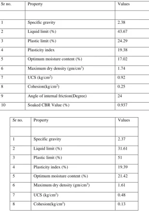
Physical and geotechnical properties of virgin soil
Table I. Basic and geotechnical properties of the virgin (uncontaminated) soil
Sr no. Property Values
1 Specific gravity 2.38
2 Liquid limit (%) 43.67
3 Plastic limit (%) 24.29
4 Plasticity index 19.38
5 Optimum moisture content (%) 17.02
6 Maximum dry density (gm/cm3) 1.74
7 UCS (kg/cm2) 0.92
8 Cohesion(kg/cm2) 0.25
9 Angle of internal friction(Degree) 24
10 Soaked CBR Value (%) 0.937
Sr no. Property Values
1 Specific gravity 2.37
2 Liquid limit (%) 31.61
3 Plastic limit (%) 51
4 Plasticity index (%) 19.39
5 Optimum moisture content (%) 21.42
6 Maximum dry density (gm/cm3) 1.61
7 UCS (kg/cm2) 0.48
Volume 2, Issue 6, December 2014
Table II. Basic and geotechnical properties of the soil contaminated by adding urea as 2.5% of dry weight of soil Table III. Basic and geotechnical properties of the soil contaminated by adding urea as 5% of dry weight of soil
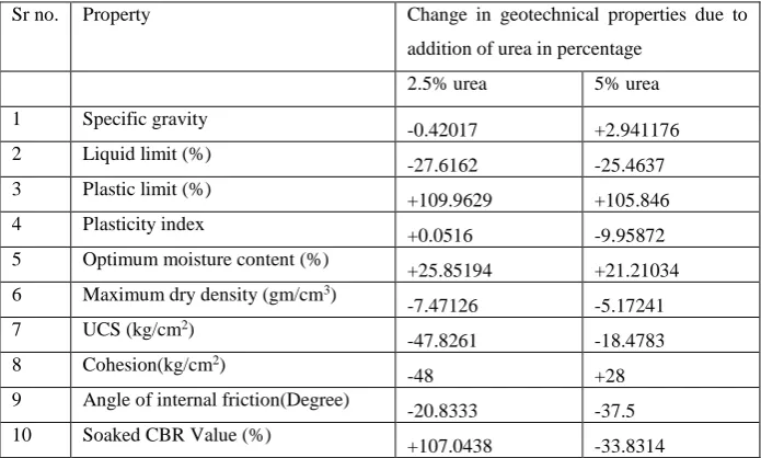
Table IV Comparison of geotechnical properties of contaminated soil with Virgin soil
Sr no. Property Change in geotechnical properties due to
addition of urea in percentage
2.5% urea 5% urea
1 Specific gravity
-0.42017 +2.941176 2 Liquid limit (%)
-27.6162 -25.4637 3 Plastic limit (%)
+109.9629 +105.846 4 Plasticity index
+0.0516 -9.95872 5 Optimum moisture content (%)
+25.85194 +21.21034 6 Maximum dry density (gm/cm3)
-7.47126 -5.17241 7 UCS (kg/cm2)
-47.8261 -18.4783 8 Cohesion(kg/cm2)
-48 +28
9 Angle of internal friction(Degree)
-20.8333 -37.5 10 Soaked CBR Value (%)
+107.0438 -33.8314
-ve sign represents decrease and +ve sign represents increase
VI. RESULTS
The results are obtained as shown in Table I, Table II and Table III. Table I shows Basic and geotechnical properties of the virgin (uncontaminated) soil, Table II shows Basic and geotechnical properties of the soil contaminated by adding urea as 2.5% of dry weight of soil and Table III shows Basic and geotechnical properties of the soil contaminated by adding urea as 5% of dry weight of soil. Table IV represents the change in geotechnical properties due to contamination in percentage with respect to virgin soil which shows that the liquid limit, unconfined compressive strength, maximum dry density, optimum moisture content and angle of internal friction values are decreased due to contamination by fertilizer for silty soils. The cohesion was seen to decrease
9 Angle of internal friction(Degree) 19
10 Soaked CBR Value (%) 1.94
Sr no. Property Values
1 Specific gravity 2.45
2 Liquid limit (%) 32.55
3 Plastic limit (%) 50
4 Plasticity index 17.45
5 Optimum moisture content (%) 20.63
6 Maximum dry density (gm/cm3) 1.65
7 UCS (kg/cm2) 0.75
8 Cohesion (kg/cm2) 0.32
9 Angle of internal friction (Degree) 15
Volume 2, Issue 6, December 2014
with 2.5% and increase with 5% fertilizer. California bearing ratio of silty soil decrease as percentage of contaminant increased.
VII. CONCLUSION
The results showed that the addition of fertilizer is less affect the Specific gravity and plasticity Index while more affect the Plastic limit and CBR value of silty soil and rest of properties are moderately affected. Contaminated silty soils might be used for geotechnical purposes and these results will benefit to engineers or decision makers in recycling or re-using of contaminated soils.
REFERENCES
[1] https://www.tumblr.com/tagged/plant-bio.
[2] I.S. 2720(Part-III, Section-II)-1980 Standard Methods of test for soils part III, Determination of Specific Gravity, Fine, Medium and Coarse Grained soil.
[3] IS: 2720, (Part V-1985), Indian Standard Methods of test for soils part V, Determination of Liquid and Plastic Limits.
[4] IS: 2720(Part 7)-1980- Methods of test for soils: Determination of water content-dry density relation using light compaction.
[5] IS: 2720, (Part X-1991), Indian Standard Methods of test for soils part X, Determination of Unconfined Compressive Strength.
[6] IS: 2720, (Part XI-1993), Indian Standard Methods of test for soils part XI, Determination of the shear strength parameters of a specimen tested in unconsolidated undrained triaxial compression without the measurement of pore water pressure.