Available Online at www.ijpret.com 47
INTERNATIONAL JOURNAL OF PURE AND
APPLIED RESEARCH IN ENGINEERING AND
TECHNOLOGY
A PATH FOR HORIZING YOUR INNOVATIVE WORK
FINITE ELEMENT ANALYSIS AND OPTIMIZATION OF TEMPORARY STEEL SHED
COVERING LARGE SPAN
HARSHIDA G. RANA1, NOOPUR A. SHAH2, SATYEN RAMANI3
1. PG Student, Department of Civil Engineering, SAL Institute of Technology and Engineering Research, Ahmedabad, Gujarat, India – 380058. 2. Assistant Professor, Department of Civil Engineering, SAL Institute of Technology and Engineering Research, Ahmedabad, Gujarat, India – 380058.
3. Assistant Professor, Department of Civil Engineering, SAL Institute of Technology and Engineering Research, Ahmedabad, Gujarat, India – 380058.
Accepted Date: 22/05/2018; Published Date: 01/06/2018
\
Abstract: - Temporary steel sheds defined here are those having short service life and used
for temporary function. They are usually made from light weight steel component. Sheds considered here are made of circular hollow sections from IS 1161-2014. Temporary sheds having different panel length and pitch of roof are analyzed here for load combinations of dead load, live load and wind load. As temporary sheds are made of light weight steel components and having short service life, earthquake loads are not considered here. Finite
element analysis and optimization of temporary steel sheds has been done by ANSYS®
Workbench in this paper.
Keywords: Temporary steel shed, Optimization, FEM, Circular hollow section, ANSYS
Workbench.
Corresponding Author: HARSHIDA G. RANA Access Online On:
www.ijpret.com
How to Cite This Article:
Available Online at www.ijpret.com 48
to the fact that service life of a temporary sheds is much shorter than a “permanent structure,” and as such, the probability of load exposure to the temporary shed are substantially less.
Available Online at www.ijpret.com 49 Fig -1: Temporary steel shed for public event
Advantages of temporary shed:
Better general appearance.
Less liable to damage through storms or lighting.
Low maintenance cost.
Less chance of faults.
The high ratio of strength to weight.
Excellent ductility and seismic resistance.
Resist extensive deformation without failure under high tensile stress.
Elasticity, uniformity of material.
Available Online at www.ijpret.com 50
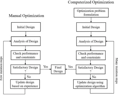
optimization we cannot optimize the solution more precisely, like computer aided optimization.
Fig -2: Difference between manual and computerized optimization
2. PROBLEM DEFINITION
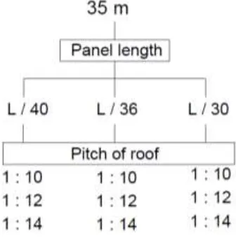
Available Online at www.ijpret.com 51 Fig -3: Configuration of models
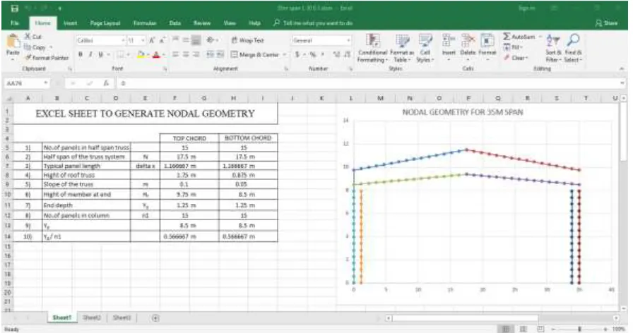
Available Online at www.ijpret.com 52 Fig -4: Nodal geometry in excel
Fig -5: JAVA script
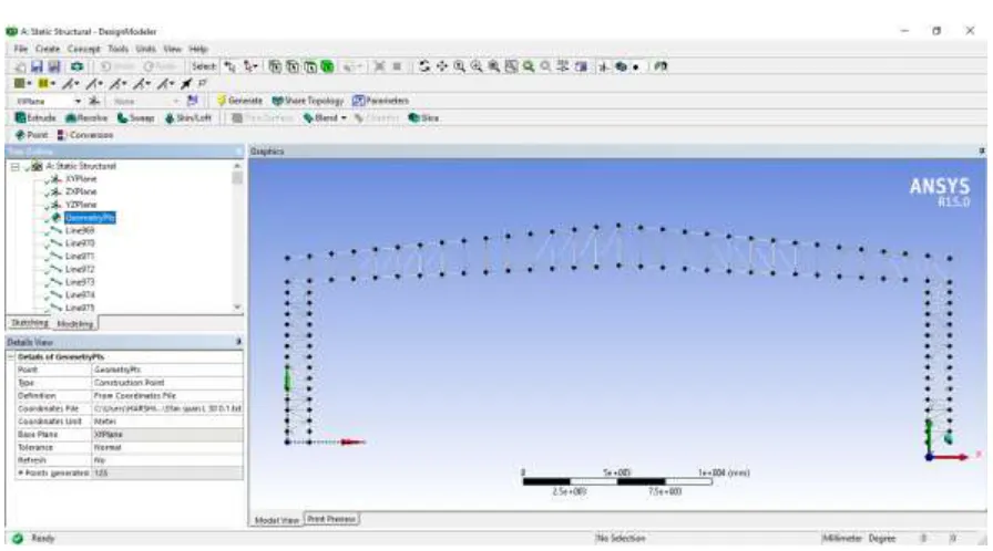
Available Online at www.ijpret.com 53 Fig -6: Model generated after run script in ANSYS
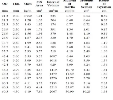
After generation of model, the different cross sections were allotted to top chord, bottom chord, column member, truss bracing and column bracing. The mesh has been generated in Mechanical part of ANSYS. The analysis has been done in static structural part. After the application of loads and support conditions to the shed, analysis has been done. The design of cross section has been done by IS 806. The circular hollow section of different diameter and thickness has been taken from IS 1161-2014.
Available Online at www.ijpret.com 54
Fig -9: Column member Fig -10: Column bracing
Fig -11: Truss bracing (Vertical) Fig -12: Truss bracing (Diagonal)
2.1 Load Calculation:
1) Dead Load (IS 875 part 1)
Dead Load of Purlin + Roof = 70 N/m2 + 131 N/m2
= 201 N/m2
2) Live Load (IS 875 part 2)
From table 2
Live load for flat, sloping or curved roof with slope up to and including 10o
And access not provided except for maintenance = 750 N/m2
Available Online at www.ijpret.com 55
Wind load calculation has been done from IS875-2015(part 3)
Location - Ahmedabad
Assume wall opening: 5 to 20 % of wall area
Height of building to eaves (h): 8.5m
Table–1: Wind load calculation
Wind load calculation for L/36 and L/40 has been done in same way as shown in table 1.
Available Online at www.ijpret.com 56 Fig -13: Loads and support condition
Available Online at www.ijpret.com 57 2.2 Permissible Displacements and Stress
Permissible displacements:
As per IS 800-2007 (Cl. 5.6.1, Table 6)
Maximum lateral displacement: Height / 150
Maximum vertical displacement: Span / 180
Permissible stresses:
As per IS 806 (Cl 5.1, Table 1)
Permissible axial stress in tension
For grade YSt 210: 122.58 N/mm2
For grade YSt 240: 147.10 N/mm2
For grade YSt 310: 186.33 N/mm2
As per IS 806 (Cl. A-2)
Permissible axial stress in compression
For values of l/r from 60 to 150, the average axial stress on the cross sectional area of the
compression member shall not exceed the values of Fc obtained by the formula given below:
Where,
Fc = the permissible average axial compressive stress
fy = minimum yield stress
m = factor of safety as 1.67
Available Online at www.ijpret.com 58
compression member shall not exceed the value Fc (1.2 – 1/750r) where Fc is obtained as given
in above formula.
3. RESULTS AND COMPARISONS
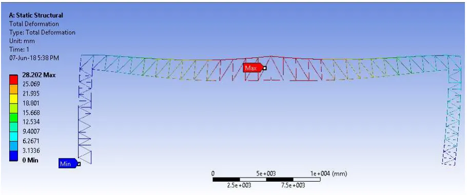
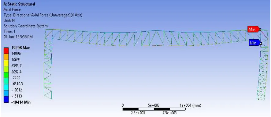
Finite element analysis of the shed in ANSYS workbench gives various results. We will consider total deformation, directional deformation, axial force and axial stress for the study.
Available Online at www.ijpret.com 59 Fig -15: Directional deformation
The axial stress will be obtained from the value of axial force and cross sectional area, axial stress = axial force/cross sectional area of member.
The circular hollow sections were selected in such a way that, their axial stresses do not exceeds the permissible values of axial stresses in tension and compression. All 9 models were analyzed from which the three critical cases of load combinations for varying panel length and pitch of roof were optimized.
Available Online at www.ijpret.com 60
For L/30 panel length, the critical load combination was DL+LL for pitch of roof 1 : 10. For L/36 panel length, the critical load combination was DL+LL for pitch of roof 1 : 12. For L/40 panel length, the critical load combination was DL+LL+WL1 for pitch of roof 1 : 12.
Table 4: Max. and Min. values
Available Online at www.ijpret.com 62 Fig -18: Design point vs. parameter
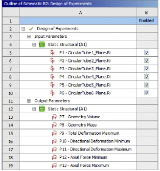
For various size of the tube, it is necessary to input the dimension of the tube manually by using CUSTOM method in Design of experiments in which we also assign them upper bound and lower bound limits. Design Points vs. Parameter graph shows the variation of the results.
Available Online at www.ijpret.com 63 Fig -20: Local sensitivity
Table 5 : 3D Response surface graph
Horizontal axis 1 Horizontal axis 2 Vertical axis
Graph 1 Circular tube 1 Circular tube 2 Directional deformation
Graph 2 Circular tube 3 Circular tube 4 Directional deformation
Graph 3 Circular tube 1 Circular tube 2 Axial force
Graph 4 Circular tube 3 Circular tube 4 Axial force
Available Online at www.ijpret.com 64
Graph 1 Graph 2
Graph 3 Graph 4
Fig -21: 3D Response surface graph
Available Online at www.ijpret.com 65 Table 6 : Max. and Min. values after optimization
5. CONCLUSION
The optimization of temporary steel sheds has been done using ANSYS workbench. The results of optimization were discussed in above section. Three models were optimized having different panel length of L/30, L/36 and L/40. Their maximum compressive axial forces were reduced by 22.95%, 26.32% and 25.53% and maximum tensile axial forces were reduced by 26.24%, 32.18% and 29.88% respectively. The mass of the sheds were decreased by 29.60%, 24.18% and 25.10% respectively after optimization by response surface method in ANSYS workbench.
REFRENCES
1. Xuefeng Cai, Zheng Zhang, “Finite Element Analysis on Integral Structure of Light Steel Temporary Buildings”, Applied Mechanics and Materials, 2013.
2. Yongchao Ma and Jizhong Zhou, “Finite Element Analysis on Frame Structure of Light Steel
Temporary Building”, Applied Mechanics and Materials, 2013.
3. Milan Masani, Dr. Y. D. Patil, “Large Span Lattice Frame Industrial Roof Structure”, IOSR
Journal of Mechanical and Civil Engineering, e-ISSN: 2278-1684, p-ISSN: 2320-334X, Volume 12,
Issue 1 Ver. IV, 2015.
4. Wenfeng Du, Chunyu Liu, Yun Sun and Qi Liu, “Design and optimization of the large span
dry-coal-shed latticed shell in Liyuan of Henan province”, Institute of Steel and Spatial Structures in School of Civil Engineering and Architecture, Henan University, MATEC Web of Conferences, 2017.
5. Petr Hradil, Matti Mielonen and Ludovic Fulop, “Advanced design and optimization of steel
Available Online at www.ijpret.com 66
9. VIJAY KRISHNA “Structural optimization using ansys classic and radial basis function based response surface models” The University of Texas at Arlington MAY 2009.
10. IS 875( Part 3 )-2015 : Code Of Practice For Design Loads (Other Than Earthquake) For Buildings And Structures
11. IS: 1893-2002 Criteria For Earthquake Resistant Design Of Structures
12. IS 875 Code Of Practice For Design Loads (Other Than Earthquake) For Buildings And
Structures Part 1 Dead Loads — Unit Weights Of Building Materials And Stored Materials
13. IS 875 Code Of Practice For Design Loads (Other Than Earthquake) For Buildings And
Structures Part 2 Imposed Loads
14. IS 1161- 2014 Steel tubes for structural purposes – specification