Management and Research
Available online at: www.ijstmr.comIJSTMR
©
2017 | All Rights Reserved 17Design, Development & Testing of Double Pipe
Heat Exchanger With Heat Transfer
Enhancement Liners
Amol Ashok Patil Dept of Mechanical Engg. D.N.Patel COE, Shahada.
Maharashtra, India
Prof. M.H.Patil Dept of Mechanical Engg.
D.N.Patel COE, Shahada. Maharashtra, India
Prof. H.G.Patil Dept of Mechanical Engg.
D.N.Patel COE, Shahada. Maharashtra, India
_________________________________________________________________________________________________ Abstract: The various techniques for achieving improved heat transfer are usually referred to as “heat transfer augmentation” or “heat transfer enhancement” and the heat exchanger provided with heat transfer enhancement techniques as “Augmented Heat Exchanger”. The objective is to reduce as many of the factors as possible: Capital Cost, Power Cost, Maintenance Cost, Space and Weight, Consistent with safety and reliability. Present work describes the principal techniques of industrial importance for the augmentation of single phase heat transfer on the inside of inserts. So inserts (liners) should be used in heat exchanger when high heat transfer rate is required and pressure drop is of no significance.
Keywords: Double Pipe Heat Exchanger, Inserts,Heat Transfer, Enhancement Liners, Flow Aggangement.
___________________________________________________________________________________________________________
I. INTRODUCTION
Heat exchangers are important engineering devices in many process industries since the efficiency and
economy of the process largely depends on the performance of the heat exchangers. High performance heat exchangers
are therefore very much required. Improvement in performance may result in reduction in size of heat exchanger.
Alternatively high performance heat exchangers of a fixed size can give an increased heat transfer rate; it might also give
a decrease in temperature difference between the process fluids enabling efficient utilization of thermodynamic
availability. The vital present day need to conserve energy and materials has resulted in huge growth in research and
development to improve heat transfer equipment design. The need to increase the thermal performance of heat
exchangers, thereby effecting energy, material & cost savings have led to development & use of many techniques termed
as Heat transfer augmentation. These techniques are also referred as Heat transfer enhancement or Intensification.
Augmentation techniques increase convective heat transfer by reducing the thermal resistance in a heat exchanger.
Inserts type of passive heat transfer augmentation techniques have shown significantly good results in past
studies. Horizontal double pipe heat exchanger uses various inserts inside tube so as to enhance heat transfer and hence
increase heat transfer coefficient .These types of heat exchangers found their applications in heat recovery processes, air
conditioning and refrigeration systems, chemical reactors, and food and dairy processes .The double pipe heat exchanger
would normally be used for many continuous systems having small to medium heavy duties. The heat exchanger is a
device which transferred the heat from hot medium to cold medium without mixed both of medium since both mediums
IJSTMR
©
2017 | All Rights Reserved 18 example, double pipe heat exchanger is used in chemical process like condensing the vapour to the liquid. When toconstruct this type of heat exchanger, the size of material that want to uses must be considered since it affected the
overall heat transfer coefficient. For this type of heat exchanger, the outlet temperature for both hot and cold fluids that
produced is estimated by using the best design of this type of heat exchanger.
II. HEAT TRANSFER ENHANCEMENT
Heat transfer enhancement is the practice of modifying a heat transfer surface to increase the heat transfer coefficient between the surface and a fluid. The effects of heat transfer enhancement are:
To reduce the heat transfer surface area required for a given application which in term reduces the heat exchanger
size and cost.
Increase the heat duty of the exchanger. Permit closer approach temperature.
All of these can be visualized from the expression for heat duty for a heat exchanger
AUGMENTEDDOUBLEPIPEHEATEXCHANGER
One of the passive methods that can be used in double pipe heat exchanger is the swirl flow method. Swirl flow can be produced by inserting liners in the tubes of double pipe heat exchanger. Inserts (liners) are a metallic plate made with Alluminium and inserted longitudinally in a tube. Usually inserts are very easy to make and fit. The inserts were snuggly fitted inside the tube.
III. EXPERIMENTAL PROCEDURE
It is essential to have calibrated instrument in order to get the good experimental results. The heat exchanger special designed for this work was calibrated and was tested for heat balance. It was found that approximate 2 to 5 % error was The set-up consisted of An water tank with heater of 0.64m3 capacity placed on floor.
1. An overhead water tank in which water is filed and heated using immersion heater. 2. A double pipe heat exchanger.
3. Beaker as a flow Measuring devices
4. Temperature indicator gauge and stop watch for measuring time.
STEPWISE PROCEDURE
1. First the plain tube double pipe heat exchanger was tested.
2. Ensure all the parts are in connection and flow arrangement is counter flow.
3. Fill the water in tank and Heat the water in the top tank up to desired temperature by using water heater.(usually 600) measured using temperature gauge.
4. At the beginning of series of tests, the hot water was circulated through inner tube and cooling water through annulus tube in counter flow configuration.
5. Start flow of hot water in downward direction for counter flow configuration
6. The flow rate of water was fixed.
7. Start cooling water pump and send water top to bottom for counter flow.
8. Take temperature readings for coldwater inlet and outlet as well as hot water inlet and outlet temperature.
9. Now, by changing the mass flow rate using valve arrangements and the Above procedure is repeated for no. of observations.
IV. PRECAUTIONS 4
1. While fabricating inserts, exact number of rotations should be measured for a given twist so that other tapes could be made of exact twist ratio.
IJSTMR
©
2017 | All Rights Reserved 19 4. Temperature readings should be taken only when the inlet & outlet temperature of both the liquids reach aconstant value.
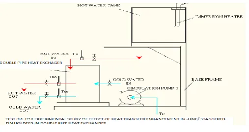
Fig 1 Schematic representation of experimental set up
First the plain tube double pipe heat exchanger was tested. At the beginning of series of tests, the hot water was circulated through inner tube and cooling water through annulus tube in counter flow configuration. The flow rate of water was fixed. The cooling water coming in heat exchanger is at room temperature. First the water flow rate was fixed. a prescribed heat input was given to the water in tank and hot water is allow to flow by opening the valve. Once the flow of hot water is start the flow rate of hot and cold water which is used as working fluid, temperature reading at inlet and outlet section of hot and cold fluid and mass flow rate readings were taken. The series of readings are taken as shown in table. The flow rate of cold water was kept constant and above procedure was repeated for different flow arrangements one after other.
After completing the test with flow rate arrangement. The flow rate will be changed which result in changing another dependant parameters and similar test is conducted with same procedure and reading are taken. The same experimental procedure was repeated with four set of inserts. Throughout the experimental work the hot water was circulated inside tube and cold water through annulus in counter as well as parallel flow arrangement.
Measurements were conducted for different types of flow rate alternatively. The comparisons in heat transfer coefficient are of obvious importance. In this work a relation of various parameters like LMTD, Capacity ratio, Resistivity and heat transfer coefficient is made counterl flow and different mass flow rate using metallic inserts as a enhancement liners.
Fig.2 Double pipe heat exchanger Fig.3 Fins Arrangement
IJSTMR
©
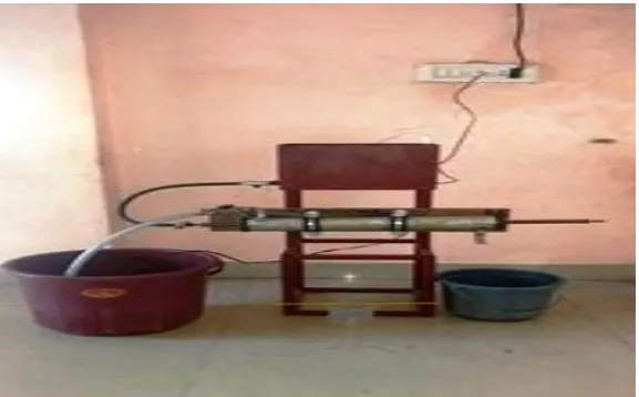
2017 | All Rights Reserved 20Fig 5 Actual experimental set up
V. RESULTS
INPUT DATA
Specific heat of water at (25 to 30 0 C) = 4187 kJ/kg-k
Density of water @ 60 0 C = 985 kg/m3
Density of water @ 30 0 C = 1000 kg/m3
OBSERVATION TABLE (SET NO. 1)
ARRANGEMENT OF COMPONENTS OF SET UP FOR COUNTER FLOW CONFIGURATION A) MASS FLOW HOT WATER
SR. NO.
VOLUME IN BEAKER(ML)
TIME (SECONDS) MASS FLOW ( HW) ( Kg/sec)
1. 200 42 0.00469
2. 200 39
0.005051
3. 200 36
0.005472
4. 200 34 0.005794
5. 200 32 0.006156
B) MASS FLOW COLD WATER
SR. NO.
VOLUME IN BEAKER(ML)
TIME (SECONDS) MASS FLOW ( Kg/sec)
1. 200 18 0.011111
2. 200 16 0.0125
3. 200 14 0.014286
4. 200 12 0.016667
IJSTMR
©
2017 | All Rights Reserved 21 C) TEMPERATURE READINGSSR.NO. COLD
WATER INLET TEMP.
( Tci)
COLD WATER OULTLET TEMP (Tco)
ΔTC
WATER
HOT WATER
INLET TEMP. ( Thi)
HOT OIL OULTLET TEMP (Tho)
ΔTH WATER
1. 28 36 8 60 55 37
2. 28 38 10 60 53 38
3. 28 35 7 60 50 41
4. 28 38 10 60 47 38
5. 28 39 11 60 45 40
RESULTABLE
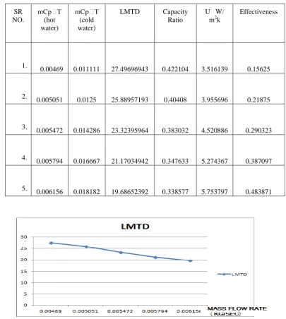
FIG 6 GRAPH OF LMTD VS FLOW RATE
SR
NO. (hot water)
(cold water)
LMTD Capacity Ratio
U W/ m2k
Effectiveness
1.
0.00469 0.011111 27.49696943 0.422104 3.516139 0.15625
2.
0.005051 0.0125 25.88957193 0.40408 3.955696 0.21875
3. 0.005472 0.014286 23.32395964 0.383032 4.520886 0.290323
4. 0.005794 0.016667 21.17034942 0.347633 5.274367 0.387097
5.
IJSTMR
©
2017 | All Rights Reserved 22FIG 7 GRAPH OF CAPACITY RATIO VS FLOW RATE
FIG 8 GRAPH OF OVERALL HEAT TRANSFER COEFFICIENT VS FLOW RATE
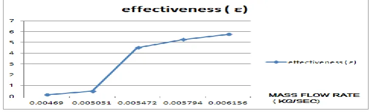
FIG 9 GRAPH OF EFFECTIVENESS VS FLOW RATE
VI. SAMPLE CALCULATIONS AND DISCUSSION
For Reading no. 1
A. FOR COUNTER FLOW ARRANGEMENTS-
1) Effectiveness= (Hot water inlet temp - Hot water outlet temp) / (Hot water inlet temp - Cold water inlet temp)
= (Th i- Tho) / (Thi - Tci)
= (60-55) /(60-28)
=0.15625
2) LMTD =(θ1-θ2) / IN(θ1/θ2)
where
IJSTMR
©
2017 | All Rights Reserved 23 = ((60-36)-(55-28)) / IN ((60-36)-(55-28))= 27.49696943
3) Capacity ratio = c = mcw / mhw
C= 0.011111 / 0.00469 =0.422104
4) Resistivity (R) =1 / mcw = 1 / 0.011111
R = 90.009
5) U = mcw / 0.00316
= 3.516139 w / m2k
CONCLUSION
From above experimental investigation it is concluded that,
LMTD decreases with increase in flow rate.
The capacity ratio decreases win increase in flow rate.
The Overall heat transfer coefficient increases with increase in flow rate. The effectiveness increases with increase in flow rate.
REFERENCE
1. B.Adrian and K. Allan D. Heat transfer enhancement. In Heat Transfer Handbook, Chapter 14, pg.1033, -1101, Wiley-interscience, 2003.
2. Bergles, A.E. ―Techniques to augment heat transfer.‖ In Handbook of Heat Transfer
Applications (Ed.W.M. Rosenhow), 1985, Ch.3 (McGraw-Hill, New York).
3. Bergles, A.E. and Blumenkrantz, A.R. ―Performance evaluation criteria for enhanced heat transfer surfaces‖. Proc. Of 5th Int. Heat Conf.,
Tokyo, Vol 2, 239-243(1974)
4. Champagne, P.R. and Bergles, A.E. "Development and testing of a novel, variable roughness technique to enhance, on demand, heat transfer
in a single-phase heat exchanger." Journal of Enhanced Heat Transfer 8, Vol 5 (2001) 341-352.
5. Megerlin et al., 1974. F.E. Megerlin, R.W. Murphy and A.E. Bergles, ―Augmentation of heat transfer in tubes by use of mesh and brush
inserts‖. J. Heat Transfer, 145– 151(1974)
6. Manglik, R. M. and Bergles, A. E. ―Heat transfer and pressure drop correlations for twisted tape insert in isothermal tubes.‖ Part 1: laminar
flows. Trans. ASME, J. Heat Transfer, 1993, 116, 881–889.
Saha, S. K., Dutta, A. and Dhal, S. K. Friction and heat transfer characteristics of laminar swirl flow through a circular tube fitted with