AM-PM: Efficient Network Telemetry
using Alternate Marking
∗Tal Mizrahi
?, Gidi Navon
•, Giuseppe Fioccola
, Mauro Cociglio
†, Mach Chen
, Greg Mirsky
◦?
Huawei Network.IO Innovation Lab,
•Marvell Semiconductors,
†Telecom Italia,
Huawei Technologies,
◦ZTE Corporation
ABSTRACT
The fast evolution of high-speed networks has raised the need for accurate and scalable network measurement. Thus, in the last few years several new methods to collect the net-work state information have been pursued by netnet-work opera-tors and vendors across the board. This paper focuses on the Alternate Marking Performance Measurement (AM-PM) ap-proach, which allows accurate measurement of performance metrics, including packet loss and delay, using two bits or less in the header of each packet. This method was doc-umented and recently published as an RFC by the Internet Engineering Task Force (IETF) [RFC 8321]. This paper pro-vides an overview of AM-PM and how it can be applied in practice. The paper also shares operational experience from a large-scale deployment and presents experimental results from an implementation of the AM-PM method.
1.
INTRODUCTION
Background
The scale of high-speed networks has grown rapidly over the past few years, raising the urgent need for flexi-ble, easy-to-manage and easy-to-troubleshoot networks. Furthermore, the constant shift of critical data into the cloud has created an even stronger dependency on the health and performance of the network, raising the need to continuously monitor and track it. Thus, the ability to monitor the performance and health of the network, to detect congestion, failures and anomalies, and to re-spond to them in real-time has become a key component in every network.
Performance measurement and monitoring protocols (see Fig. 1) have been deployed nearly since the dawn of communication networks. Passive monitoring has always been a common approach, using counters and statistics that can be collected from network devices using SNMP or NETCONF.1. The well-known Ping is the bread and butter of enterprise network
administra-∗
Accepted to IEEE Network, 2019. This manuscript is a pre-published version.
1
The Simple Network Management Protocol [1] or the Net-work Configuration Protocol [2].
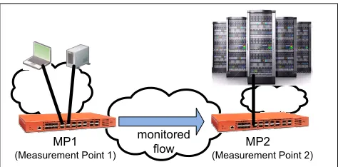
MP1 monitored MP2 flow
(Measurement Point 1) (Measurement Point 2)
Figure 1: Performance measurement between two Measurement Points, MP1 and MP2. A measurement can be performed between two or more hosts, servers, or network devices.
tors, and various Operations, Administration and Main-tenance (OAM) tools [3] have been broadly deployed in carrier networks for many years. However, large-scale networks have outgrown some of these traditional tools. Thus, several new telemetry methods have been intro-duced in the last few years.
One of the most important requirements of network measurement solutions isfate sharing; packets used for measuring the network must share the fate of data pack-ets in order to present reliable measurement informa-tion. This important property is one of the key advan-tages of AM-PM.
Alternate Marking (AM-PM)
AM-PM is an efficient method that measures network flows by using a very small number of bits in each data packet: one or two bits, or even as few as zero bits per packet. It guarantees fate sharing and provides accurate and reliable measurement with a negligible overhead.
As network telemetry is continuing to gain momen-tum, and as approaches such as INT and IOAM2are be-ing adopted, AM-PM is a complementary method that can be deployed alongside INT and IOAM, and
pro-2
vides operators with a tool for continuous periodically sampled telemetry information with an extremely low overhead.
AM-PM is currently under development in the Inter-net Engineering Task Force (IETF); the concept and methodology were recently published as an RFC [6]. Applications of AM-PM are being considered in the con-text of various encapsulations, including Geneve, SFC NSH, BIER, MPLS, and QUIC. Notably, AM-PM can also be applied over existing network protocols such IP, as further discussed below. AM-PM is under discussion in six working groups in the IETF, and is being pursued in several internet drafts, written by over 20 different authors, indicating the wide interest in AM-PM from various vendors and operators.
This paper provides a tutorial of AM-PM, and intro-duces new and efficient AM-PM variants that require zero or one bit per packet, including multiplexed mark-ing, pulse marking and hashed marking.3 The paper in-cludes experience from a large-scale deployment of AM-PM, and experimental results from a hardware-based implementation. Finally, the paper also introduces an approach that allows AM-PM to be used for on-path collection, serving as a complementary method to other network telemetry protocols.
2.
AM-PM OVERVIEW
When AM-PM is used, every packet carries one or two marking bits. These bits are used for signaling and co-ordinating the measurement between two or more mea-surement points.
AM-PM Abstractions
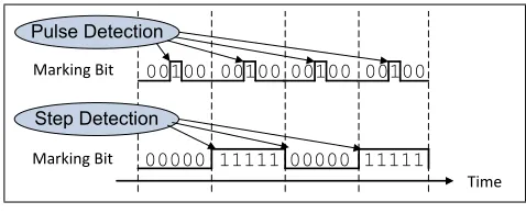
AM-PM makes use of two basic abstractions,pulse de-tection, andstep detection,4 as illustrated in Fig. 2.
• Pulse: a pulse is detected when the value of the marking bit is toggled in a single packet, and re-turns to its previous value in the following packets.
• Step: a step is detected when the value of the marking bit is toggled, and remains at the new value in the following packets.
These abstractions can be used by the MPs to signal a measurement event. A measurement event can be for example, ‘store the timestamp of the current packet’, or ‘start using counter 1 instead of counter 0’.
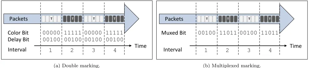
Double Marking
The simplest variant of AM-PM is called the double marking method (see Fig. 3a). In this method the
3
These new variants were presented in an internet draft [7], but were not formally published prior to this paper. 4
Borrowing from signal processing terminology.
Time Marking Bit 00000 11111 00000 11111
Marking Bit 00100 00100 00100 00100
Step Detection Pulse Detection
Figure 2: Pulse and step detection.
header of every data packet sent between two measure-ment points, MP1 and MP2 (see Fig. 1) includes two marking bits. One bit is used as a color indicator, and the other is used as a delay measurement (DM) indica-tor.
• The color bit is toggled periodically, defining dis-tinct time intervals, so that in each time interval the color bit is either ‘0’ or ‘1’. The color bit is used for loss measurement (LM). Each of the MPs maintains two counters,5 one per color. At the end of each interval the counter values can be col-lected by a central Collector and analyzed. For example, at the end of a ‘0’ interval, counter 0 is collected from both MPs, and the packet loss dur-ing the interval can be computed by compardur-ing the counter values of the two MPs. The alternating color mechanism is the core of AM-PM, enabling accurate loss measurement.
• The delay bit is used to mark specific packets that are used as a reference for delay measurement. When a packet has the delay bit set, both MPs store the timestamp of that packet. The two times-tamps,T1andT2, corresponding toM P1andM P2, can be collected from each of the MPs by the Col-lector, which can compute the one-way path delay: T2−T1.
Double marking uses the pulse abstraction (see Fig. 2) for triggering a DM event, and the step abstraction for switching between counters for LM.
Note that when step detection is used for LM, as in the double marking approach, it is resilient to out-of-order delivery. For example, when observing a step from ‘0’ to ‘1’, every packet received with a ‘0’ marking bit is counted using counter ‘0’, and every packet received with a ‘1’ is counted using counter ‘1’. Therefore, count-ing is performed consistently even if packets are not re-ceived in-order during or around the step detection.
Data Collection
The measurement data (counters and timestamps) is periodically collected by a central Collector such as an
5
Time Color Bit 00000 11111 00000 11111
T T T T
Packets
Interval 1 2 3 4
Delay Bit 00100 00100 00100 00100
(a) Double marking.
Time Muxed Bit 00100 11011 00100 11011
T T T T
Packets
Interval 1 2 3 4
(b) Multiplexed marking.
Figure 3: Alternate Marking methods.
The packets used as a reference for delay measurement are marked with a ‘T’.
analytics server, a Network Management System (NMS) or a Software Defined Network (SDN) controller. The data can either be streamed to the Collector or collected by it.
Specifically, the collection of the counters must be performed in a way that guarantees that the counter values are stable; counter 0 must be read safely after the color bit was toggled from ‘0’ to ‘1’, and safely before it was toggled back to ‘0’. Thus, the counter of one of the colors is collected roughly at or around the middle of the interval, while the counter of the other color is being actively used.
AM-PM in Practice
As mentioned above, AM-PM is under development in the IETF in the context of various encapsulation proto-cols. An interesting question in this context is: where do we find the spare bits to use as marking bits? There are three possible ways to tackle this problem:
• Dedicated bits: the simplest approach is to dedi-cate one or two bits in the packet header for AM-PM. This approach is currently under considera-tion in the IETF for new protocols such as BIER, SFC NSH, Geneve, and QUIC.6
• Reserved values in existing fields: rather then us-ing dedicated bits, AM-PM can make use of a ded-icated value in an existing field. A specific value (or set of values) of the field can represent the marking value ‘1’, while other values represent the marking value ‘0’. For example, this approach was proposed in MPLS, by having two sets of MPLS labels [8], representing either ‘0’ or ‘1’ in the vir-tual marking bit. Similarly, this approach can be used in IPv4 or IPv6 using two sets of values in the DSCP field, as further discussed in Section 4. It should be noted that it may be risky to use re-served values when running packets over the wide
6
The QUIC ‘spin bit’ is a variant of the AM-PM color bit, in which the bit value is not toggled periodically, but flipped on every round-trip.
Internet. Thus, this approach can only be applied in administrative domains in which it is guaran-teed that using these reserved values does not have unwanted impact on the network.
• Zero-bit marking: this approach enables AM-PM to be implemented without any impact on the packet encapsulation. Zero-bit marking is further described in the next section. While the advantages of this approach are obvious, it may sometimes be am-biguous regarding the measurement accuracy, as further discussed in Section 3.
3.
ADVANCED MARKING METHODS
Double marking is a straightforward method that is relatively easy to implement, but ‘costs’ two bits per packet. Interestingly, AM-PM can be used more ef-ficiently, in a way that requires just a single bit per packet, or even zero bits per packet.
Notably, various variants of AM-PM may be consid-ered, presenting a trade-off in terms of factors such as implementation simplicity or resilience to out-of-order delivery. Thus, we present a few AM-PM variants, with a short discussion about the pros and cons of each method.
3.1
Single-bit Marking
Single-bit Marking using the First Packet
In this method each packet incorporates a single mark-ing bit, used as a color indicator. Step detection (see Fig. 2) is used for both color toggling, and for DM; the first packet of each interval is used by both MPs as a reference for DM. Thus, the timestamp of this packet is measured by the two MPs, and can be collected by the Collector.
Pros. This approach requires just a single marking
bit, and is relatively simple to implement.
Cons. DM is not accurate when packets arrive
different view of which packet was the first in the inter-val.
Single-bit Pulse Marking
In this single-bit approach pulse detection (see Fig. 2) is used as a trigger for both loss and delay measurement. The two MPs maintain a single per-flow counter for LM, in contrast to the color-based methods which require two counters per flow. In each interval a single packet is marked with ‘1’, while the rest of the packets are marked with ‘0’. The marked packet triggers two events in each of MPs:
• The timestamp is captured for DM.
• The value of the counter is captured for LM.
In each period, each of the MPs exports the times-tamp and counter-stimes-tamp to the Collector, which can then compute the loss and delay in that period.
Pros. This approach requires a single marking bit,
and a single counter.
Cons. Since both LM and DM use a pulse-based
trigger, if the marked packet is lost between MP1 and MP2 then no measurement is available in this period. Moreover, the LM accuracy may be affected by out-of-order delivery.
Single-bit Multiplexed Marking
In multiplexed marking the color indicator and the times-tamp indicator from the double marking method are multiplexed into a single bit.
Double marking uses two 1-bit values: a color indica-torC, and a timestamp indicator T. The multiplexed marking bit, denoted byM, is an exclusive or between these two values: M =C⊕T.
As illustrated in Fig. 3b, in each interval one of the packets is marked for DM. In each of these designated packets the value of the multiplexed bit is reversed com-pared to the other packets in the same block, allow-ing MP2 to distallow-inguish the designated packets from the other packets.
Pros. Multiplexed marking requires just a single bit,
and is not affected by out-of-order delivery or by single packet drops.
Cons. The bit multiplexing may be more difficult to
implement than some of the previous methods.
3.2
Hashed Marking
Zero-bit Hashed Marking
Hash-based selection [9] is a well-known method for sampling a subset of packets. This method can be lever-aged for marking specific packets. For example, let’s consider two MPs that computes a 10-bit hash over each packet; if the hash value is equal to 0, the packet’s
timestamp and the current value of the counter are ex-ported to the Collector. Thus, on average one of every 1000 packets will be ‘marked’, somewhat similarly to the pulse marking approach, but without any marking bits.
Formally7, a Hash Functionh() maps the packet con-tentc, or some portion of it, onto a Hash RangeR. The packet is selected if h(c) is an element of S, which is a subset ofRcalled the Hash Selection Range.
In hash-based marking, a packet is selected if h(c) is an element ofS, which is a strict subset of the hash rangeR. It is assumed that both MPs are preconfigured with the same hash function, and the sameS.
Hashed marking requires zero bits per packet; the un-derlying encapsulation is not affected by the measure-ment, and no data plane overhead is imposed.
Note that as opposed to the double marking and sin-gle marking methods, hashed sampling is not based on fixed time intervals, as the duration between sampled packets depends only on the hash value. Thus, consec-utive or close packets may be assigned the same hash value, making it difficult for the Collector to correlate the measurements from the two MPs, and causing am-biguity in the measurement. Thus, if two hashed mea-surements are closer than a predefined threshold, they are ignored in order to avoid a potential measurement error. Note that when|S|<< |R|,8 the probability of ambiguity between consecutive measurements is low.
Pros. Hashed marking requires zero overhead on the
data plane, and does not affect the encapsulating pro-tocol.
Cons. The measurement may be ambiguous if
con-secutive or proximate packets have the same hash value, causing measurements to be ignored.
Single-bit Hashed Marking
Single-bit hashed marking is a hybrid approach that combines the single marking approach with hash-based sampling. A single marking bit is used in the packet header as a color indicator, while a hash-based pulse is used to trigger DM. The marking bit guarantees the accuracy of the loss measurement, while the hash-based trigger is used selectively, as in the zero-bit hash ap-proach.
Pros. Accurate loss measurement without the
po-tential ambiguity of the zero-bit approach.
Cons. DM has the same drawback as the zero-bit
approach, but since the marking interval is used as a reference, the ambiguity is mitigated in some of the hash collision scenarios.
7
As defined in [9]. 8|S|
Figure 4: Screen capture from an NMS in Telecom Italia’s AM-PM deployment. The data is reported in real-time and the granularity of the information is 5 minutes. For each monitored eNodeB the connection towards the mobile core network is measured and is partitioned into access network link and metro network link. The eNodeB has a spot located in the downstream direction of the access network link, indicating packet loss. Some of the more detailed information has been cropped from the figure due to confidentiality.
4.
OPERATIONAL EXPERIENCE AND
EX-PERIMENTAL EVALUATION
4.1
Experience from a Large-scale Deployment
Overview
Alternate Marking was first introduced by Telecom Italia in [10]. The foundational elements of the technique have been tested and deployed, and the lessons learned from the operational experience inspired the formalization of AM-PM as detailed earlier.
The methodology has been employed by leveraging functions and tools available on off-the-shelf routers. It is currently being used to monitor packet loss in some portions of Telecom Italia’s production network. The application of the method to delay measurement is still under evaluation in Telecom Italia’s labs.
The Deployment Scenario
The operational deployment is applied to multicast IPTV channels and to Mobile Backhaul traffic realized with MPLS-based Virtual Private Networks (VPNs). Around 10000 eNodeBs are currently monitored in these net-work segments with a maximum of 1000 monitored flows per router.
With current off-the-shelf routers, only QoS-related fields and features offer the required flexibility to set bits in the packet header. Specifically, the 6-bit Dif-ferentiated Services Code Point (DSCP) field in the IP header9 is leveraged for marking in AM-PM. In case a Service Provider only uses the three most significant
9
This approach is applicable to both IPv4 and IPv6 traffic, as the DSCP field is present in both IP versions.
bits (IP Precedence) of the DSCP field for QoS classi-fication and queuing, it is possible to use the two least significant bits of the DSCP field to implement AM-PM (for marking the traffic) without affecting QoS policies. Monitored flows in the deployment scenario are iden-tified by all the packets sharing the same source IP ad-dress or the same destination IP adad-dress, depending on the direction. Thus, the IP address of an eNodeB is the source address of the flow to be monitored on the upstream direction, while it is the destination address in the downstream direction. Once the flow has been defined, the traffic is marked using the DSCP field by configuring the Provider Edge (PE) router with an ac-cess list that intercepts all the monitored flows and ap-plies a policy that sets the DSCP field as described in Section 2. The traffic marking is performed by an auto-matic script that is loaded into the router and modifies the policy on the basis of a fixed timer. Since the traffic is alternately marked over time, the on-path routers can perform the counting and an access list that matches the two DSCP values in order to count the packets of the monitored flows. The automatic script, on all the on-path routers, sends out the packet counters to the Network Management System (NMS) that collects all the counters and any other data and is responsible for packet loss calculation. The AM-PM interval, and con-sequently also the cycle of the automatic script, is set to 5 minutes, which was found to be a safe choice for the stability of the measurement and is also coherent with the reporting window of the NMS. Fig. 4 shows a screenshot of the NMS Graphical User Interface.
the following fields: the timestamp that is useful to rec-ognize the measurement period, the flow identification that can be the source or the destination IP address, the flow direction, the interface, the DSCP value and the corresponding counter.
The NMS is aware of the network topology and by using the previous information can calculate the packet loss for the different links and nodes of each flow.
It is important to highlight that since the QoS field is used for marking, it is essential to guarantee trans-parency outside the monitoring domain. This is per-formed with the restoration of the initial DSCP value for all the packets leaving the two PE nodes of the Mo-bile Backhaul MPLS VPN.
The current deployment performs loss measurement for each eNodeB. Current off-the-shelf equipment does not provide native support for AM-PM delay measure-ment, as described in Section 2. An alternative DM approach that is under evaluation is to use flow mon-itoring, provided by IPFIX [11], in order to recognize the timestamps of the first and last packet of each in-terval in order to enable the single-bit marking method using the first packet of the flow for DM (similar to Sec-tion 3.1). This approach is being evaluated in Telecom Italia’s labs at the time of writing.
Summary
The main takeaway from this operational experience is that AM-PM can be deployed effectively for loss mea-surement using existing off-the-shelf routers, even though these devices were not intended to support AM-PM. In-terestingly, AM-PM is used with zero data plane over-head, as it makes use of unused bits10in the IPv4 DSCP field. As mentioned above, the AM-PM interval is cur-rently set to 5 minutes, which can be significantly re-duced with future routers that will have explicit AM-PM support.
4.2
Evaluation of an AM-PM Implementation
Overview
This experiment evaluates an implementation of AM-PM over a Marvell switch device. We use a microbench-mark to demonstrate the feasibility and accuracy of AM-PM for loss and delay measurement. Both the loss and the delay measurement were performed accurately by the switch silicon. The TimeFlip [12] method was used in order to periodically toggle the color; TimeFlip is a method that uses the packet’s timestamp as part of the switch’s flow classification process. Thus, the color toggling is performed in hardware, and the AM-PM interval can be as low as one second or less. Further details about the AM-PM implementation are provided in [13].
10
Unused in the current network.
Traffic Generator Management
Monitored data flow
Background traffic
Switch 1
Switch 2 Collector
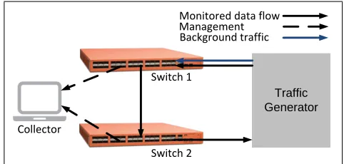
Figure 5: AM-PM test setup using Marvell switches.
Test Setup
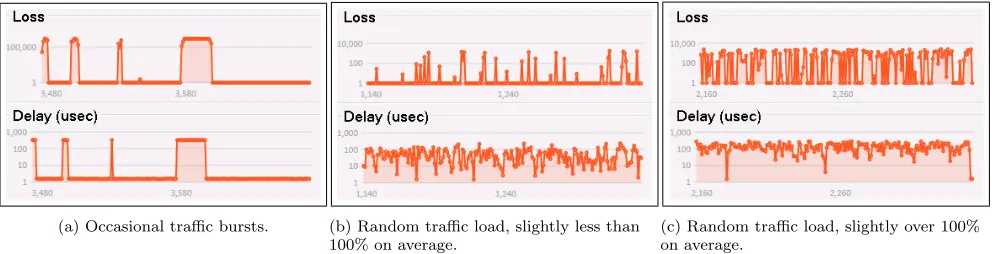
The test setup is illustrated in Fig. 5. Two Marvell switches were used as MPs, and an off-the-shelf traffic generator was used for generating traffic at a rate of 10 Gbps. The multiplexed marking method was used to measure loss and delay between the two devices, and the least significant bit of the DSCP field was used as the marking bit. The marking bit was toggled period-ically by Switch 1, with a period of 1 second, and one packet in the middle of each period was used as a ref-erence for delay measurement (see Fig. 3b). The two MPs were synchronized using the Precision Time Pro-tocol (PTP), reaching a sub-microsecond synchroniza-tion accuracy. In order to create synthetic congessynchroniza-tion in Switch 1, a background flow was transmitted from the Traffic Generator to Switch 1, creating congestion at the port leading to Switch 2. Three congestion sce-narios are shown in the figure: (a) constant traffic rate of 10 Gbps with occasional bursts of 20 Gbps, (b) ran-dom traffic rate at slightly less than 10 Gbps,11and (c) random traffic rate at slightly over 10 Gbps.
Measurement Results
The measurement results were monitored by a Collector that was attached to the two devices, and periodically collected the measurement results (every 1 second). A screenshot of the measurement results is shown in Fig. 6. As illustrated in Fig. 6, when the background flow is en-abled, both the loss and delay are temporarily increased, until the additional flow is disabled. The loss and delay measurement results were as expected, confirming that AM-PM can be implemented accurately over commod-ity switch silicons.
5.
DISCUSSION
Multipoint Marking
Throughout the paper we assumed that the measure-ment takes place between two MPs. The approach can
11
(a) Occasional traffic bursts. (b) Random traffic load, slightly less than 100% on average.
(c) Random traffic load, slightly over 100% on average.
Figure 6: Loss and delay measurement results: The horizontal axis represents the time in seconds. The vertical axis represents the number of packets lost per second (in the top graph), and the packet delay in microseconds, denoted by usec (bottom graph).
be generalized to include multipoint measurements, as further discussed in [14].
Time Synchronization
AM-PM loss measurement requires the MPs and the Collector to be synchronized at the interval level. This relaxed synchronization requirement allows the Collec-tor to collect the counters safely after the interval has ended, and to correlate the intervals from both MPs.
The DM method described in Section 2 assumes that the two MPs have synchronized clocks, thus allowing to compute the delay by comparing the timestamps. 12
Measurement Accuracy
As discussed above, the accuracy of delay measurement in AM-PM mostly depends on the accuracy of the time synchronization method that is used in the system. Loss measurement is guaranteed to be accurate as long as the network is phase-synchronized at the interval-level. Any inaccuracies related to out-of-order delivery, dropped packets, or hash collisions can be avoided, for example, by using double marking or multiplexed marking.
Measurement Frequency
Since AM-PM is based on using fixed time intervals, operators can increase the measurement frequency by reducing the time interval, thereby allowing fine-grained measurement. As described in the previous section, the Telecom Italia deployment uses an interval of 5 minutes, but the microbenchmark showed that the interval can be reduced to 1 second or less, depending on the network equipment capabilities.
12
The requirement for the synchronized clocks can be avoided if the traffic flow is bidirectional, and AM-PM is used on both directions. Thus, instead of measuring the one-way-delay, the Collector can compute the two-way-delay without requiring the two MPs to be synchronized.
Management Overhead
At a first glance the small overhead in AM-PM sounds too good to be true; two bits or less per packet. In-deed, one must also consider the management overhead, of sending the telemetry information to the Collector. Moreover, short measurement intervals will yield a pro-portionally high management overhead. Thus, the mea-surement granularity and management overhead are strictly related. Admittedly, management overhead is expected in all network telemetry approaches, and not just in AM-PM. The good news is that the cost of the management overhead does not compromise the data plane performance, i.e., the cost should be taken into account but is taken from a different budget.
On-path Collection of AM-PM Measured Performance
Metrics
In some cases it may be desirable to collect detailed per-packet telemetry information, as performed in INT or in IOAM, but without the data plane overhead of piggybacking this information onto data packets. In-deed, network performance can be monitored without adding overhead to data plane packets, as performed in widely-used protocols [15, 16] or in recently introduced ones (e.g., [17]).
Notably, a possible way to collect fine-grained infor-mation without the data plane overhead is to select spe-cific packets and mark them, thus allowing the switches along the path to detect the marked packets, and ex-port their required telemetry information. AM-PM can be used for marking designated packets for out-of-band collection of INT-style or IOAM-style telemetry infor-mation.
switches along the path.
Implementation and Deployment Tradeoffs
One of the major questions that come to mind is how does AM-PM compare against other network measure-ment approaches in terms of implemeasure-mentation and ployment aspects. The analysis of [13] presented a de-tailed implementation approach of AM-PM that was applied to two implementations, one hardware-based and the other software-based. A variant of AM-PM is also implemented in existing commodity network de-vices [18]. These AM-PM implementations, as well as the evaluation in Section 4, show that AM-PM is rea-sonably simple to implement in typical network devices. A network operator that deploys AM-PM will enjoy the benefit of continuous measurement at the cost of just one or two bits per packet, and will typically deploy other complementary measurement mechanisms that can be invoked periodically or on-demand, providing more detailed measurement information at the cost of higher overhead.
6.
CONCLUSION
AM-PM is an efficient and accurate method for mea-suring performance with no data plane overhead, or with the negligible overhead of up to two bits per packet. AM-PM can be deployed using some of the existing off-the-shelf network equipment. As the complexity of net-works continues to grow and as automated operation and service quality assurance are increasingly becom-ing essential, we expect that AM-PM will provide use-ful insight into service quality to complement existing methods of measurement and state information collec-tion, providing timely available data for analysis by au-tomated network operation systems using principles of machine learning and artificial intelligence.
7.
REFERENCES
[1] Jeffery Case, Mark Fedor, Martin Schoffstall, and C Davin. A simple network management protocol (SNMP). RFC 1157, IETF, 1990.
[2] R Enns, M Bjorklund, J Schoenwaelder, and A Bierman. Network configuration protocol (NETCONF). RFC 6241, IETF, 2011. [3] T Mizrahi, N Sprecher, E Bellagamba, and
Y Weingarten. An Overview of Operations, Administration, and Maintenance (OAM) Tools. RFC 7276, IETF, 2014.
[4] Changhoon Kim, Parag Bhide, Ed Doe, Hugh Holbrook, Anoop Ghanwani, Dan Daly, Mukesh Hira, and Bruce Davie. In-band network
telemetry (INT). technical specification, P4, 2016. [5] Frank Brockners, Shwetha Bhandari, Carlos
Pignataro, Hannes Gredler, John Leddy, Stephen Youell, Tal Mizrahi, David Mozes, Petr Lapukhov,
Remy Chang, Daniel Bernier, and John Lemon. Data Fields for In-situ OAM.
draft-ietf-ippm-ioam-data, work in progress, IETF, 2019.
[6] Giuseppe Fioccola, Alessandro Capello, Mauro Cociglio, Luca Castaldelli, Mach Chen, Lianshu Zheng, Greg Mirsky, and Tal Mizrahi.
Alternate-Marking Method for Passive and Hybrid Performance Monitoring. RFC 8321, IETF, 2018.
[7] Tal Mizrahi, Carmi Arad, Giuseppe Fioccola, Mauro Cociglio, Mach Chen, Lianshu Zheng, and Greg Mirsky. Compact Alternate Marking Methods for Passive Performance Monitoring. draft-mizrahi-ippm-compact-alternate-marking, work in progress, IETF, 2018.
[8] Stewart Bryant, Mach Chen, Zhenbin Li, George Swallow, Siva Sivabalan, Greg Mirsky, and Giuseppe Fioccola. RFC6374 Synonymous Flow Labels. draft-ietf-mpls-rfc6374-sfl, work in progress, IETF, 2018.
[9] Tanja Zseby, Maurizio Molina, Nick Duffield, Saverio Niccolini, and Frederic Raspall. Sampling and filtering techniques for ip packet selection. RFC 5475, IETF, 2009.
[10] Mauro Cociglio, Alessandro Capello, Alberto Tempia Bonda, and Luca Castaldelli. A packet-based method for passive performance monitoring. draft-tempia-opsawg-p3m-00, expired, 2011.
[11] Benoit Claise, Brian Trammell, and Paul Aitken. Specification of the IP Flow Information Export (IPFIX) protocol for the exchange of flow information. RFC 7011, IETF, 2013.
[12] Tal Mizrahi, Ori Rottenstreich, and Yoram Moses. TimeFlip: Scheduling network updates with timestamp-based TCAM ranges. InIEEE INFOCOM, 2015.
[13] Alon Riesenberg, Yonnie Kirzon, Michael Bunin, Elad Galili, Gidi Navon, and Tal Mizrahi. Time-multiplexed parsing in marking-based network telemetry. accepted to acm systor, 2019. [14] Giuseppe Fioccola, Mauro Cociglio, Amedeo
Sapio, and Riccardo Sisto. Multipoint Alternate Marking method for passive and hybrid
performance monitoring.
draft-ietf-ippm-multipoint-alt-mark, work in progress, IETF, 2019.
[15] ITU-T G.8013/Y.1731. OAM functions and mechanisms for Ethernet based networks. 2015. [16] Kaynam Hedayat, Roman M. Krzanowski,
Al Morton, Kiho Yum, and Jozef Babiarz. A two-way active measurement protocol (TWAMP). RFC 5357, IETF, 2008.
Hybrid Two-Step Performance Measurement Method. draft-mirsky-ippm-hybrid-two-step, work in progress, IETF, 2018.