University of New Orleans Theses and
Dissertations Dissertations and Theses
12-20-2002
A Service Discovery-Enabled LCD Projector Device
A Service Discovery-Enabled LCD Projector Device
Jeevan Kale
University of New Orleans
Follow this and additional works at: https://scholarworks.uno.edu/td
Recommended Citation Recommended Citation
Kale, Jeevan, "A Service Discovery-Enabled LCD Projector Device" (2002). University of New Orleans Theses and Dissertations. 6.
https://scholarworks.uno.edu/td/6
A Thesis
Submitted to the Graduate Faculty of the University of New Orleans In partial fulfillment of the Requirements for the degree of
Master of Science in
The Department of Computer Science
by
Jeevan Kale
B.E., Pune Institute of Computer Technology, Pune, India, 1999
ACKNOWLEDGEMENT
I would like to express my deepest appreciation towards my thesis advisor Dr. Golden
Richard III, for sharing his knowledge and providing me with many helpful comments. He was
very patient and cheerful throughout the duration of my thesis. I would also like to thank him for
providing me his book on ‘Service and Device Discovery’. It was a great help towards clarifying
the concepts and writing the report as well.
I would like to thank Dr. Markus Montigel and Dr. Ming-Hsing Chiu for being on my
thesis committee. It was a great honor having them both. I would like to give my special thanks
to Dr. Montigel for his valuable help in pointing out the mistakes in the report and help making it
more understandable, and a worthwhile one.
I would like to thank my family members for being patient, for all their support and love.
I am grateful to have Amit, Pushkar, Sanjay, Ashwini and Urmila in my life. They really make
my world a better place.
I am grateful to the city of New Orleans for all the good times, wonderful people, great
experiences and all the wonderful memories it has engraved onto my heart.
TABLE OF CONTENTS
ACKNOWLEDGEMENT ... ii
TABLE OF CONTENTS... iii
LIST OF FIGURES ... iv
LIST OF CODE LISTS ...v
ABSTRACT... vi
CHAPTER 1 INTRODUCTION ...1
2 BACKGROUND ...5
2.1 Service Discovery ...5
2.2 Universal Plug and Play...11
2.3 Java Native Interface...26
3 SYSTEM DESCRIPTION AND DESIGN ...36
3.1 System Description ...36
3.2 System Design ...38
3.3 System Architecture...42
3.4 Working Scenario ...51
4 IMPLEMENTATION...52
4.1 The API Selection...52
4.2 Implementation Overview ...53
4.3 Implementation of the Description Documents ...57
4.4 Implementation of Device and Control Point ...62
5 CONCLUSION AND FUTURE WORK ...93
5.1 Conclusion ...93
5.2 Future Work ...95
REFERENCES ...96
LIST OF FIGURES
Fig 2.1 Components of the UPnP network ...18
Fig 2.2 The UPnP Protocol Stack ...21
Fig 2.3 GUI and Client application interaction using JNI ...28
Fig 2.4 Steps writing native methods for Java programs...29
Fig 2.5 Graphical representation of native method names ...32
Fig 2.6 Java Object types ...34
Fig 3.1 Graphical User Interface...39
Fig 3.2 Interaction between GUI and Control Point ...40
Fig 3.3 Virtual Control Point ...40
Fig 3.4 Virtual Projector Device...41
Fig 3.5 System Architecture ...43
Fig 3.6 Working Scenario ...51
LIST OF CODE LISTS
CodeList 4.1: ProjectorDevDesc.xml; Root Device Description Document... 57-58
CodeList 4.2: ProjectorPowerSCPD.xml, Power Service Description Document ... 58-59
CodeList 4.3: ProjectorPresSCPD.xml; Presentation Service Description Document... 59-60
CodeList 4.4: ProjectorSlideCtrlSCPD.xml; Slide-Control Service Description Document .. 61-62
CodeList 4.5: Projector.c; Projector Device implementation ... 63-71
CodeList 4.6: nativeLib.c; Control Point implementation... 72-90
CodeList 4.7: Function ParseItem() from common.c ...91
ABSTRACT
The widespread deployment of inexpensive communications technology, computational
resources in the networking infrastructure and network-enabled end devices pose a problem for
end users: how to locate a particular network service or device out of those accessible. Service
providers use Service Discovery Services (SDS) to advertise the descriptions of available or
already running services, while clients use SDS to compose queries for locating these services.
Service descriptions and queries use the eXtensible Markup Language (XML9) to encode vendor
specific information and device- or service-specific capabilities as well as the actions addressed
to the device or service. This report presents the architecture and implementation of a SDS used
to locate enabled LCD projectors and use them for presentation. The presentation service
provides all the capabilities to the end user so that he can choose the projector device of his
interest and use the graphical user interface to navigate thorough the presentation. The
presentation service also has the capability to use more than one projector at a time. We use the
Universal Plug and Play7 suite of protocols to establish the communication between client and
CHAPTER 1. INTRODUCTION
Service discovery1 allows clients to perform discovery in order to find needed services.
Clients do so by multicasting their discovery request on the network. In order for clients to
perform discovery, they need to know very little about their environment. On the other hand,
when a service enters the network, it performs service advertisement, either directly to clients or
to service catalogs. The advertisement has necessary contact information, and will also include
either descriptive attributes or information that will allow these attributes to be discovered. After
a client has found the service of their interest they can make use of all the services provided by
the service.
In my application, I have implemented a virtual projector device that allows operating an
LCD projector remotely. The projector device acts as the device driver for the LCD projector. It
provides all the basic function of the LCD projector and makes is convenient for the user to
perform the slide show or presentation. The set of functionalities provided by the projector
device are broadly categorized into three service groups:
• Power Service
• Presentation Service
The power service allows the user to turn on / off the projector. A presentation can only
be performed if the projector is on.
The presentation service allows the user to choose the presentation. In our application the
slides used for the presentation are JPEG image file named serially like ‘1.jpg’, ‘2.jpg’,
…’n.jpg’. And they are stored in a directory, the name of which is used as the presentation name.
We use ‘Electric Eyes’, an image displaying software to display our slides.
The slide-control service allows all the basic functions required to perform the
presentation. It is absolutely necessary to set the slide-range, i.e. how many slides are present in
the presentation. The functions provided are: viewing next slide, previous slide, jump to a
particular slide, the slide number for which is accepted from the user and display a blank slide.
The LCD projector application achieves the following service discovery capabilities, which are
discussed more in detail in the section 2.1.3.
• Discovery of services1
The client can know all the projector devices on the network. The devices are discovered
using the device type (‘Projector’).
• Service Advertisement1
Whenever the projector device becomes available, it advertises its presence and the service
offered. Each advertisement has a timer associated with it. If it expires without further
• Service browsing1
A Graphical User Interface is created on the client side, which can show all the available
services and the user can select the one of interest.
• Eventing1
Eventing provides asynchronous notification of the interesting conditions like changes in the
state of a service; e.g. a printer needs a change of toner. Eventing makes the developer’s job
easier, eliminating the use of polling to watch for service state changes. Whenever there are
changes in the device state, e.g. “projector power turned on”, the client is notified of the change.
We will discuss this in more detail in section 4.2.
The interesting feature implemented in this application is that one can simultaneously operate
more than one projector at a time. A ‘queue’ is implemented which keeps track of all the
projector devices. Using the GUI user can switch between the available projectors.
The entire system is developed under the Red Hat Linux platform with Intel UPnP SDK
v1.0.34. All the coding was written in C except the GUI was implemented in Java to make it
portable across various platforms. The Java Native Interface2 (JNI) is used to communicate
between the GUI and client side. We will discuss more about JNI in chapter 2.
The rest of the chapters are organized as follows: In chapter 2 we talk in detail about service
discovery technology. We will also talk about UPnP4, the technology we use to achieve the
service discovery paradigm and in detail about JNI technology provided by Java, which we use
architecture of the projector service we have implemented. It also describes a working scenario
of the projector service. Chapter 4 explains the implementation of the service. Finally chapter 5
CHAPTER 2. BACKGROUND
2.1 Service Discovery1
A service discovery framework is a collection of protocols for developing dynamic
client/server applications. Enabled services announce their presence when they enter the network
and (if possible) announce their demise while leaving the network. Service catalogs are used to
track the available services on the network. Garbage collection facilities clean up the system by
removing outdated information. Service discovery technologies generalize and standardize the
environments in which client/server applications are developed and used, and provide software
tools that make the development effort much easier and the interactions between clients and
services more dynamic.
In the service discovery framework, clients perform discovery in order to find needed
services. Clients either may directly seek the needed service themselves or else they may contact
one or more service catalogs. Clients do so by multicasting their discovery request on the
network. Clients need to do very little or no static configuration prior to dynamically locate the
needed service, and clients need very little information about their environment.
When a service enters the network, it performs service advertisement, either directly to
include either descriptive attributes or information that will allow these attributes to be
discovered.
A major problem one has to deal with is the installation, configuration and management
of peripherals. The complexity of this problem is becoming more serious as laptops, handheld
computers, printers, scanners and other peripherals are integrated into networked environments.
It is quite possible that a new user might get frustrated with all the installation routines. For
experienced users it is a waste of valuable time. Service discovery technologies take an
important step toward eliminating manually installed device drivers, relying instead on standard
interfaces to put devices in touch. Service discovery technologies allow services introduced in
the network to be discovered, configured and used with a minimum manual intervention.
In a networked environment with services like printing, storage, scanning etc., it is
inconvenient to manually determine the services available to users. Service discovery can make
things more convenient by allowing the types of available services to be discovered easily. And
since the interfaces between client and server are standardized, the client can get to work quickly
without manual configuration.
2.1.1 Service Discovery Technologies
In this section we briefly discuss several leading service discovery technologies including Jini10,
2.1.1.1 Jini10
Jini is a service discovery technology based on Java, developed by Sun Microsystems. Because
of the platform-independent nature of Java, Jini can rely on mobile code to control services.
Lookup services provide catalogs of available services to clients in a Jini network. Jini services
register their availability by uploading proxy objects to one or more of these lookup services.
The proxy objects are essentially “device drivers” written in Java – they allow interaction with
the service. Clients can dynamically discover lookup services, search for interesting services, and
then download these proxy objects. Searching is based on the type of proxy objects and on sets
of descriptive attributes. Jini requires that at least one lookup service is accessible. Clients and
services in Jini cannot discover each other directly.
2.1.1.2 Service Location Protocol11 (SLP)
SLP is an IETF standards-track protocol for IP-based networks. It is language neutral, although
APIs are defined for C and Java. In SLP, User agents (UAs) search for needed services on behalf
of clients. Service agents (SAs) advertise the availability of services, either directly to UAs or to
Directory agents (DAs), if at least one DA is available. Directory agents serve some of the
purposes of the lookup servers in Jini by cataloging available services, but they store only
contact information – not code. Service location information in SLP is encoded in service URLs,
which contain all the information necessary for contacting a service. In contrast to Jini, SLP is
concerned primarily with putting clients in touch with services – the specific protocol spoken
between clients and services are outside the scope of SLP. Service templates are used to
standardize particular service types (such as print services). They also provide the syntax of
interesting services by service type, further narrowing searches by the values of descriptive
attributes.
2.1.1.3 Universal Plug and Play4 (UPnP)
Universal Plug and Play is a set of protocols for service discovery under development by the
Universal Plug and Play forum, an industry consortium by Microsoft. UPnP standardizes the
protocols used to communicate between clients and services. Device and service descriptions are
coded in XML and a number of protocols for auto configuration, discovery, advertisement,
client/server interaction and eventing-Auto-IP4, SSDP4, SOAP4 and GENA4- are included in the
specification. These protocols are based on existing standards like HTTP. Unlike Jini and SLP,
UPnP does not support service directories. The communication between devices and clients is
always direct.
We use Universal Plug and Play technique for our implementations. One of the most significant
reasons for using UPnP is that it gives the choice of language and operating system to be used for
the implementation. Also, UPnP provides the flexibility to leverage lower layers of the protocol
stack where this makes sense, thereby keeping UPnP designs simple and effective. A detailed
description of this technology is given in the following chapter.
2.1.2 Common Characteristics
Despite their differences, current service discovery technologies like Jini, UPnP, and SLP share
• Discovery of services
Needed services may be discovered on demand, with minimal prior knowledge of
network. Typically, clients can search for services by type (“projector”) or by descriptive
attributes (“manufacturer name”) or by both.
• Service “subtyping”
A client may be interested in a very specific type of service; for example, a
high-resolution color laser printer with duplex capability. A client needing services like these must
make these needs known. On the other hand, a client who is searching for a basic printer should
be able to discover one without knowing many details. Service subtyping allows the detailed
attributes of the printer to be defined. So the client needing to print can be as specific as he
wishes to be.
• Service insertion and advertisement
Services can enter into the network with minimal manual intervention and advertise their
availability directly either to clients or to servers maintaining service catalogs. Conversely,
services leaving a network can advertise their demise. The main difference between service
discovery technologies and static information services such as DHCP12 is that service discovery
technologies allow highly dynamic updates – services appearing or disappearing result in
immediate updates. Service discovery technologies also provide more powerful searching
capabilities than the static information services. For example, static information systems such as
DHCP can search for an IP address for a machine from a specified range of addresses. This range
are based on dynamic input from the client who is looking for a particular service. Clients can
search for services based upon their type, unique names or specific descriptive attributes. Service
discovery technique supports this wide range of inputs, which make its searching capabilities
very powerful.
• Service browsing
A client can browse the list of available services and can choose the one of interest. A
GUI can be used to give the list of available services that a client can use.
• Catalogs of available services
Some service discovery technologies use service catalogs to keep track of available
services. Services register their availability with the catalogs and clients can obtain contact
information for the service of interest directly from the catalog. The service catalogs reduce the
multicast traffic, but add another component to be administered. Jini uses service catalogs, while
in UPnP, clients and services can directly address each other using multicast for the purpose of
discovery or advertisement. SLP supports catalogs but their deployment is optional.
• Eventing
Eventing provides asynchronous notification of the interesting conditions like changes in
the state of a service; e.g. printer needs a change of toner. Eventing makes the developer’s job
• Garbage collection
Garbage collection mechanisms are normally included in a service discovery framework
to expire the service availability information, to remove the outdated information from catalogs
of available services, and to terminate client initiated eventing. Leases are a popular way of
garbage collection, used in Jini. In SLP and UPnP, garbage collection facility is implemented
using a timer associated with the advertisement requests. If the timer expires without receiving
an advertisement requests from the service, the service is assumed to be inaccessible.
2.2 Universal Plug and Play
Among all the available service discovery suites we use UPnP technology to achieve service
discovery. In this section we will talk about UPnP in depth. The following sections describe the
responsibilities of UPnP, the steps involved in UPnP networking, components of the UPnP
network and the protocol stack of UPnP.
2.2.1 Overview
Universal Plug and Play (UPnP) is the architecture for pervasive peer-to-peer network
connectivity of PCs of all form factors, intelligent appliances and wireless devices. UPnP is a
distributed, open networking architecture. With the addition of Device Plug and Play (PnP)
capabilities to the operating system it became a great deal easier to setup, configure and add
peripherals to a PC. Universal Plug and Play (UPnP) extends this simplicity to include the entire
network, enabling discovery and control of networked devices and services, such as
UPnP is more than just a simple extension of the Plug and Play peripheral model. It is
designed to support zero-configuration, “invisible” networking and automatic discovery for a
breadth of device categories from a wide range of vendors.
2.2.2 How Universal Plug and Play Works
With UPnP, a device can dynamically join a network, obtain an IP address, convey its
capabilities, and learn about the presence and capabilities of other devices – all automatically,
truly enabling zero configuration networks. Devices can subsequently communicate with each
other directly, thereby further enabling peer to peer networking.
The varieties of device types that can benefit from the UPnP enabled network are large
and include intelligent appliances, wireless devices, and PCs of all form factors. UPnP can be
used in scenarios like home automation, printing audio/video entertainment, and automobile
networks.
UPnP uses standard TCP/IP and Internet protocols. Using these standardized protocols
allows UPnP to benefit from the use of existing technology and thereby making interoperability
easier. Because UPnP is a distributed, open network architecture, defined by the protocols used,
it is independent of any particular operating system, programming language, or physical
medium. UPnP does not specify the APIs applications will use, allowing programmers to create
2.2.3 The Responsibilities of Universal Plug and Play
UPnP provides support for communication between control points; i.e. clients and
devices. The network media, the TCP/IP protocol suite and HTTP provide basic network
connectivity and addressing needed. On top of these open, standard, Internet based protocols,
UPnP defines a set of HTTP-based protocols to handle discovery, description, control, events,
and presentation.
This section describes how the protocols defined earlier in this article are used to provide
for these needs.
2.2.4 Steps Involved in UPnP Networking
Universal Plug and Play networking involves following six steps:
1. Addressing
2. Discovery
3. Description
4. Control
5. Eventing
6. Presentation
2.2.4.1 Addressing
The foundation for UPnP networking is the TCP/IP protocol suite and the key to this
suite is addressing. Each device must have a Dynamic Host Configuration Protocol (DHCP)
DHCP server is available, the device must use the IP address assigned to it. If no DHCP server is
available, the device must use Auto IP to get an address.
In brief, Auto IP defines how a device intelligently chooses an IP address from a set of
reserved private addresses, and is able to move easily between managed and unmanaged
networks.
A device may implement higher layer protocols outside of UPnP that use friendly names
for devices. In these cases, it becomes necessary to resolve friendly host (device) names to IP
address. Domain Name Services18 (DNS) are usually used for this. A device that requires or uses
this functionality may include a DNS client and may support dynamic DNS registration for its
own name to address mapping.
2.2.4.2 Discovery
Once devices are attached to the network and addressed appropriately, discovery can take
place. Discovery is handled by Simple Service Discovery Protocol (SSDP), which will be
discussed in the following section. When a device is added to the network, SSDP allows this
device to advertise its services to control points on the network. When a control point is added to
the network, SSDP allows that control point to search for devices of interest on the network.
The fundamental exchange in both cases is a discovery message containing a few,
essential specifics about the device or one of its services, for example its type, identifier, and a
pointer to its XML device description document. This document provides general information
2.2.4.3 Description
The next step in UPnP networking is description. After a control point has discovered a
device, the control point still knows very little about the device. For the control point to learn
more about the device and its capabilities, or to interact with the device, the control point must
retrieve the device's description from the URL provided by the device in the discovery message.
Devices may contain other logical devices and services. The UPnP description for a
device is expressed in XML and includes vendor-specific manufacturer information, including
the model name and number, serial number, manufacturer name, URLs to vendor-specific Web
sites, and so forth. The description also includes a list of any embedded devices or services, as
well as URLs for control, eventing, and presentation.
2.2.4.4 Control
After a control point has retrieved a description of the device, the control point has the
essentials for device control. To learn more about the service, a control point must retrieve a
detailed UPnP description for each service. The description for a service is also expressed in
XML and includes a list of the commands, or actions, the service responds to, and parameters or
arguments for each action. The description for a service also includes a list of variables; these
variables model the state of the service at run time, and are described in terms of their data type,
range, and event characteristics.
To control a device, a control point sends an action request to a device's service. To do
in the device description). Control messages are also expressed in XML using Simple Object
Access Protocol (SOAP), which will be discussed in the following section.
In response to the control message, the service returns action specific values or fault
codes.
2.2.4.5 Eventing
The UPnP description for a service includes a list of actions the service responds to and a
list of variables that model the state of the service at run time. The service publishes updates
when these variables change, and a control point may subscribe to receive this information.
The service publishes updates by sending event messages. Event messages contain the
names of one or more state variables and the current value of those variables. These messages
are also expressed in XML and formatted using General Event Notification Architecture
(GENA), which will be discussed in the following section.
A special initial event message is sent when a control point first subscribes; this event
message contains the names and values for all evented variables and allows the subscriber to
initialize its model of the state of the service.
To support multiple control points, all subscribers are sent all event messages, subscribers
receive event messages for all evented variables, and event messages are sent no matter why the
2.2.4.6 Presentation
If a device has a URL for presentation, then the control point can retrieve a page from
this URL, load the page into a browser and depending on the capabilities of the page allow a user
to control the device and/or view device status. The degree to which each of these can be
accomplished depends on the specific capabilities of the presentation page and device.
2.2.5 Components of the UPnP Network
Figure 2.1 shows the basic building blocks of the UPnP network. They are devices, services and
control points.
2.2.5.1 Devices
The UPnP device is a container of services and nested devices. For instance, a VCR
device may consist of a tape transport service, a tuner service, and a clock service. A TV/VCR
combo device would consist not just of services, but of nested sets of devices as well.
Different categories of UPnP devices will be associated with different sets of services and
embedded devices. For instance, services within a VCR will be different than those within a
printer. Consequently, different working groups will standardize the set of services that a
particular device type will provide. This information is captured in an XML device description
document that the device must host. In addition to the set of services, the device description also
Fig 2.1 Components of the UPnP network5
UPnP Enabled Device
UPnP Enabled Device
UPnP Enabled Device Device
Service 1 Service 2
Control Point Device
Service
Root Device
Embedded Device
Service1 Service2 Service
Service
State Table
Control Server
Event Server
2.2.5.2 Services
The smallest unit of control in the UPnP network is a service. A service exposes actions
and models its state with state variables. For instance, a clock service could be modeled as
having a state variable, current_time, which defines the state of the clock, and two actions,
set_time and get_time, which allow users to control the service. Similar to the device description,
this information is part of an XML service description standardized by the UPnP forum. A
pointer (URL) to these service descriptions is contained within the device description document.
Devices may contain multiple services.
A service in the UPnP device consists of a state table, a control server and an event
server. The state table models the state of the service through state variables and updates them
when the state changes. The control server receives action requests (such as set_time), executes
them, and updates the state table and returns responses. The event server publishes events to
interested subscribers anytime the state of the service changes. For instance, a fire alarm service
would send an event to interested subscribers when its state changes to “ringing.”
2.2.5.3 Control Points
A control point in the UPnP network is a controller capable of discovering and controlling
other devices. After discovery, a control point could:
• Retrieve the device description and get a list of associated services.
• Retrieve service descriptions for interesting services.
• Subscribe to the service’s event source. Anytime the state of the service changes, the
event server will send an event to the control point.
It is expected that devices will incorporate control point functionality (and vice-versa) to
enable true peer-to-peer networking.
2.2.6 The UPnP protocol stack
UPnP leverages many existing, standard protocols. Using these standardized protocols
aids in ensuring interoperability between vendor implementations. The protocols used to
implement UPnP are found in use on the Internet and on local area networks everywhere. This
prevalence ensures that there is a large pool of people knowledgeable in implementing and
deploying solutions based on these protocols. Since the same protocols are already in use, little
would need to be done to make UPnP devices work in an existing networked environment. Some
of the protocols used to implement UPnP are summarized in the rest of this section.
The UPnP Device Architecture defines a schema or template for creating device and
service descriptions for any device or service type. Individual working committees subsequently
standardize on various device and service types and create a template for each individual device
or service type. Finally, a vendor fills in this template with information specific to the device or
service, such as the device name, model number, manufacturer name and URL to the service
description. This data is then encapsulated in the UPnP-specific protocols defined in the UPnP
The required UPnP specific information is inserted into all messages before they are
formatted using SSDP, GENA, and SOAP and delivered via HTTP, HTTPU, or HTTPMU,
which are discussed in the following section.
Figure 2.2 depicts how the UPnP protocol stack is organized. We explain each of the protocols in
the following section.
Fig 2.2 The UPnP Protocol Stack5
2.2.6.1 UPnP Specific Protocols
UPnP vendors, UPnP Forum Working Committees and the UPnP Device Architecture
document define the highest layer protocols used to implement UPnP. Based on the device
architecture, the working committees define specifications specific to device types such as
VCRs, HVAC systems, dishwashers, and other appliances. Subsequently, UPnP Device Vendors
add the data specific to their devices such as the model name, URL, etc. UPnP Vendor Defined
UPnP Forum Working Committee Defined
UPnP Device Architecture Defined
HTTPMU (Discovery)
GENA
SSDP HTTPU
(Discovery)
SSDP (Control)SOAP
HTTP (Description)
HTTP GENA (Events)
UDP TCP
2.2.6.1.1 TCP/IP5
The TCP/IP networking protocol stack serves as the base on which the rest of the UPnP
protocols are built. By using the standard, prevalent TCP/IP protocol suite, UPnP leverages the
protocol’s ability to span different physical media and ensures multiple vendor interoperability.
UPnP devices can use many of the protocols in the TCP/IP stack including TCP, UDP, ARP and
IP. How these protocols and services are used to provide what is required for UPnP to work will
become clear as we discuss the other protocols in this section and discuss how UPnP works in
subsequent sections.
Since TCP/IP is one of the most ubiquitous networking protocols, locating or creating an
implementation for the UPnP device that is tuned for footprint and/or performance is relatively
easy.
2.2.6.1.2 HTTP5, HTTPU5, HTTPMU5
TCP/IP provides the base protocol stack to provide network connectivity between UPnP
devices. HTTP, which is hugely responsible for the success of the Internet, is also a core part of
UPnP. All aspects of UPnP build on top of HTTP or its variants.
HTTPU (and HTTPMU) are variants of HTTP defined to deliver messages on top of
UDP/IP instead of TCP/IP. These protocols are used by SSDP, described next. The basic
message formats used by these protocols adheres with that of HTTP and is required both for
multicast communication and when message delivery does not require the overhead associated
2.2.6.1.3 SSDP5
Simple Service Discovery Protocol (SSDP), as the name implies, defines how network
services can be discovered on the network. SSDP is built on HTTPU and HTTPMU and defines
methods both for a control point to locate resources of interest on the network, and for devices to
announce their availability on the network. By defining the use of both search requests and
presence announcements, SSDP eliminates the overhead that would be necessary if only one of
these mechanisms is used. As a result, every control point on the network has complete
information on network state while keeping network traffic low.
Both control points and devices use SSDP. The UPnP control point, upon booting up, can
send an SSDP search request (over HTTPMU), to discover devices and services that are
available on the network. The control point can refine the search to find only devices of a
particular type (such as a VCR), particular services (such as devices with clock services) or even
a particular device, using its universally unique ID.
UPnP devices listen to the multicast port. Upon receiving a search request, the device
examines the search criteria to determine if they match. If a match is found, a unicast SSDP
(over HTTPU) response is sent to the control point. Similarly, a device, upon being plugged into
the network, will send out multiple multicast SSDP presence announcements advertising the
services it supports. Both presence announcements and unicast device response messages contain
a pointer to the location of the device description document, which has information on the set of
properties and services supported by the device. In addition to the discovery capabilities
network (bye-bye notification) and includes cache timeouts to purge stale information for self
healing.
2.2.6.1.4 GENA5
Generic Event Notification Architecture (GENA) was defined to provide the ability to
send and receive notifications using HTTP over TCP/IP and multicast UDP. GENA also defines
the concepts of subscribers and publishers of notifications to enable events.
GENA formats are used in UPnP to create the presence announcements to be sent using
Simple Service Discovery Protocol (SSDP) and to provide the ability to signal changes in service
state for UPnP eventing. A control point interested in receiving event notifications will subscribe
to an event source by sending a request that includes the service of interest, a location to send the
events to and a subscription time for the event notification.
The subscription must be renewed periodically to continue to receive notifications, and
can also be canceled using GENA.
2.2.6.1.5 SOAP5
Simple Object Access Protocol (SOAP) defines the use of Extensible Markup Language
(XML) and HTTP to execute remote procedure calls. It is becoming the standard for RPC based
communication over the Internet. By making use of the Internet’s existing infrastructure, it can
work effectively with firewalls and proxies. SOAP can also make use of Secure Sockets Layer
(SSL) for security and use HTTP’s connection management facilities, thereby making distributed
Much like a remote procedure call, UPnP uses SOAP to deliver control messages to
devices and return results or errors back to control points.
Each UPnP control request is a SOAP message that contains the action to invoke along
with a set of parameters. The response is a SOAP message as well and contains the status, a
return value and any return parameters.
2.2.6.1.6 XML
The eXtensible Markup Language (XML), to use the W3C5 definition, is the universal
format for structured data on the Web. In other words, XML is a way to place nearly any kind of
structured data into a text file.
XML looks a lot like HTML in that it uses tags and attributes. Actually, it is quite
different in that these tags and attributes are not globally defined as to their meaning, but are
interpreted within the context of their use. These features of XML make it a good fit for
developing schemas for various document types. The use of XML as a schema language is
defined by the W3C5. XML is a core part of UPnP used in device and service descriptions,
2.3 Java Native Interface2
In our LCD projector application, we have implemented the GUI in Java. Implementing GUI in
Java makes it portable as well as easier to code because of the various AWT14 libraries available.
The backend client application is implemented in C, which a problem of communication between
the GUI and the client application. The solution to this problem is the Java Native Interface
(JNI), a native programming interface for Java.
2.3.1 Overview
The Java Native Interface (JNI) is the native programming interface for Java that is part
of the JDK. The JNI allows Java code that runs within a Java Virtual Machine14 (VM) to operate
with applications and libraries written in other languages, such as C, C++, and assembly. In
addition, the Invocation API allows programmers to embed the Java Virtual Machine into the
native applications. Programmers use the JNI to write native methods to handle those situations
when an application cannot be written entirely in the Java programming language. For example,
one may need to use native methods and the JNI in the following situations:
• The standard Java class library may not support the platform-dependent features needed
by the application.
• One may already have a library or application written in another programming language
and wishes to make it accessible to Java applications.
• One may want to implement a small portion of time-critical code in a lower-level
programming language, such as assembly, and then have a Java application call these
Programming through the JNI framework lets the programmer use native methods to do
many operations. Native methods may either originate from legacy applications or they may be
written explicitly to solve a problem that is best handled outside of the Java programming
environment. The JNI framework lets a native method utilize the Java objects in the same way
that Java code uses these objects. A native method can create Java objects, including arrays and
strings, and then inspect and use these objects to perform its tasks. A native method can also
inspect and use objects created by Java application code. A native method can even update Java
objects that it created or that were passed to it, and these updated objects are available to the Java
application. Thus, both the native language side and the Java side of an application can create,
update, and access Java objects and then share these objects between them. Native methods can
also easily call Java methods. Often, one will already have developed a library of Java methods.
The native method does not need "re-invent the wheel" to perform functionality already
incorporated in existing Java methods. The native method, using the JNI framework, can call the
existing Java method, pass it the required parameters, and get the results back when the method
completes.
JNI makes available the advantages of the Java programming language to native
methods. In particular, one can catch and throw exceptions from the native method and have
these exceptions handled in the Java application. Native methods can also get information about
Java classes. By calling special JNI functions, native methods can load Java classes and obtain
class information. Finally, native methods can use the JNI to perform runtime type checking.
It is easy to see that the JNI serves as the glue between Java and native applications.
Fig 2.3 GUI and Client application interaction using JNI2
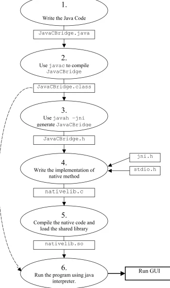
2.3.2 Writing a Java Program with Native Methods
1. Begin by writing the Java program. Create a Java class that declares the native method; this
class contains the declaration or signature for the native method. It also includes a main
method, which calls the native method.
2. Compile the Java class that declares the native method and the main method.
3. Generate a header file for the native method using javah with the native interface flag -jni.
Once the header file is generated one can have the formal signature for his native method.
4. Write the implementation of the native method in the programming language such as C or
C++.
5. Compile the header and implementation files into a shared library file.
6. Run the Java program.
J
N
I doInitialization (ip,port)
sendCommand (cmd,input)
retrieveCommandResult ( )
Exceptions
JavaCBridge Class
Java VM
Fig 2.4 Steps writing native methods for Java programs8
1.
Write the Java Code
2.
Use javac to compile
JavaCBridge
3.
Use javah –jni
generate JavaCBridge
6.
Run the program using java interpreter.
4.
Write the implementation of native method
5.
Compile the native code and load the shared library
JavaCBridge.java
nativelib.so
nativelib.c
JavaCBridge.class
JavaCBridge.h
jni.h
stdio.h
2.3.3 Integrating Java and Native Programs
The Java Native Interface defines a standard naming and calling convention so that the
Java Virtual Machine (VM) can locate and invoke the native methods. This section shows how to
follow the JNI naming and calling conventions so that one can use JNI functions from a native
method. It also explains how to declare types so that both the Java program and the native
method can correctly recognize them.
2.3.4 Declaring Native Methods
This section illustrates how to declare a native method in Java and how to generate the
corresponding C/C++ function prototype.
2.3.4.1 The Java Side
Our example, JavaCBridge.java, contains a native method that accepts a Java string,
sends it to the native implementation and performs respective control operation. The program
calls the native method, which waits for user input and then returns the result of the control
operation.
The GUI class accepts an input from the user if necessary, which invokes the
JavaCBridge object, and intern a native method named sendCommand, which is declared as
follows:
Notice that the declarations for native methods are almost identical to the declarations for
regular, non-native Java methods. However, we declare native methods differently, as follows:
• First, native methods must have the native keyword. The native keyword informs
the Java compiler that the implementation for this method is provided in another
language.
• Secondly, the native method declaration is terminated with a semicolon (the statement
terminator symbol) because the Java class file does not include implementations for
native methods.
2.3.4.2 The Native Language Side
One must declare and implement native methods in a native language, such as C or C++. Before
doing this, it is helpful to generate the header file that contains the function prototype for the
native method implementation.
Compile the Prompt.java file and then generate the .h file.
javac JavaCBridge.java
Once successfully compiled JavaCBridge.java and have created the JavaCBridge.class file, one
can generate a JNI-style header file by specifying a -jni option to javah:
javah -jni JavaCBridge
Examine the JavaCBridge.h file. Note the function prototype for the native method
JNIEXPORT jint JNICALL
Java_JavaCBridge_sendCommand (JNIEnv *, jobject, jstring, jstring);
The native method function definition in the implementation code must match the generated
function signature in the header file. JNIEXPORT and JNICALL must always be included in the
native method function signatures. JNIEXPORT and JNICALL ensure that the source code
compiles on platforms such as Microsoft Windows that require special keywords for functions
exported from dynamic link libraries.
Native method names are concatenated from the following components:
• the prefix Java_
• the fully qualified class name
• an underscore "_" separator
• the method name
Fig 2.5 shows how it looks like graphically,
Prefix + fully qualified class name + underscore “_” + method name
+ + +
Java_JavaCBridge_sendCommand
Fig 2.5 Graphical representation of native method names8
Thus, the native code implementation for the JavaCBridge.sendCommand method becomes
Java_JavaCBridge_sendCommand. (Remember that no package name component appears
because the JavaCBridge class is in the default package.)
Each native method has two parameters in addition to those parameters that is declared on the
Java side. The first parameter, JNIEnv *, is the JNI interface pointer. This interface pointer is
organized as a function table, with every JNI function at a known table entry point. The native
method invokes specific JNI functions to access Java objects through the JNIEnv * pointer. The
jobject parameter is a reference to the object itself (it is like the ‘this’ pointer in Java).
2.3.5 Mapping between Java and Native Types
In this section, we will see how to reference Java types from the native method. One needs to do
this when he wants to:
• Access arguments passed in to a native method from a Java application.
• Create Java objects in the native method.
• Have the native method return results to the caller.
2.3.5.1 Java Primitive Types
A native method can directly access Java primitive types such as booleans, integers, floats, and
so on, that are passed from programs written in Java. For example, the Java type boolean maps to
the native language type jboolean (represented as unsigned 8 bits), while the Java type float maps
to the native language type jfloat (represented by 32 bits). The following table describes the
2.3.5.2 Primitive Types and Native Equivalents8
Java Type Native Type Size in bits
boolean jboolean 8, unsigned
byte jbyte 8
char jchar 16, unsigned
short jshort 16
int jint 32
long jlong 64
float jfloat 32
double jdouble 64
void void n/a
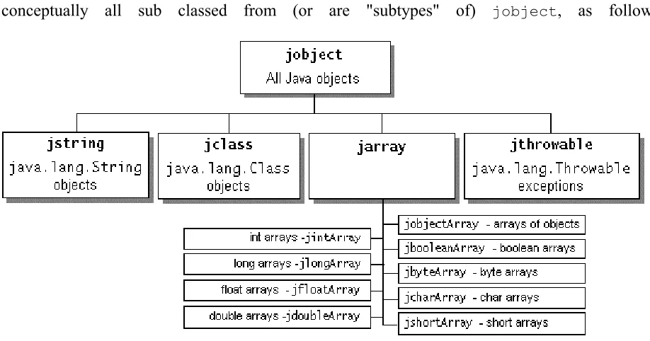
2.3.5.3 Java Object Types
Java objects are passed by reference. All references to Java objects have the type jobject. For
convenience and to avoid programming errors, the JNI implements a set of types that are
conceptually all sub classed from (or are "subtypes" of) jobject, as follows:
In our JavaCBridge.java example, the native method sendCommand takes two Java strings as
arguments and returns a Java int:
public native int sendCommand (String cmd, String input);
Its corresponding native implementation has type jstring for the arguments and jint for the return
value:
JNIEXPORT jint JNICALL
Java_JavaCBridge_sendCommand (JNIEnv *, jobject, jstring, jstring);
Graphically, this looks as follows:
public native int sendCommand(String cmd, String input);
JNIEXPORT jint JNICALL Java_JavaCBridge_sendCommand(JNIEnv *, jobject, jstring, jstring);
As mentioned above, jstring corresponds to the Java type String and jint corresponds to the Java
type int. Notice that the second argument to Java_JavaCBridge_sendCommand, which is the
CHAPTER 3. SYSTEM DESCRIPTION AND DESIGN
3.1 System Description
We use the LCD Projector device system to demonstrate the service discovery paradigm. It is a
real life projector, which is used to display the presentation. This system consists of two major
units:
• Virtual Projector Device
• Client Unit
The virtual projector device advertises its presence over the network, informs its
capabilities to the interested control point, performs the duties mentioned in the control actions it
receives from the control points, and sends out the events as a result of change in the control
variables. It consists of the following three services:
• Power Management Service
• Slide Control Service
• Presentation Service.
The power management service is used to power on / off the selected projector from the list of
available projectors at the control point. The projector can be used to display the slides only if it
The slide control service provides all the slide presentation related functions. Prior to using any
slide control functions one must set the slide range first; it indicates the number of slides in the
presentation. The functions include set slide range, go to next slide, see the previous slide, go to
a particular slide, and display blank slide.
The presentation related service allows to select the presentation that user wants to show. It is the
name of the directory where all the slides are stored. Slides are the JPEG image files numbered
‘1.jpg’, ‘2.jpg’, ‘3.jpg’, …, ‘n.jpg’. The presentation must be selected prior to starting the slide
show. ‘n’ represents the number of slides in the presentation; the slide range.
The Client Unit, which discovers the projector device and uses the services described
above, consists of two major components:
• Graphical User Interface
• Virtual Control Point.
The GUI provides the user interface for the entire system. The GUI can be used to search for
available projector devices over the network, select the device of interest out of the available
devices, select the presentation, set the slide range and perform a slide show using available
controls to view next slide, go to previous slide, jump to a slide and display blank slide.
The main function of the virtual control point is keep track of available projector devices over
the network. When a user selects the device of interest via GUI, it can download the necessary
information about the device. It can subscribe to receive interesting events, send control actions
(e.g. set presentation, advance slide etc.) to the device of interest and track the changes in the
3.2 System Design
The LCD projector system is designed in such a way that the users of the system can make use of
all the services, which are provided by the projector device. The complete system can be broadly
categorized into three units:
• Graphical User Interface
• Virtual Control Point
• Virtual Projector Device
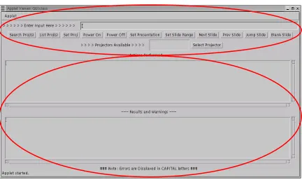
3.2.1 Graphical User Interface
It consists mainly of two parts:
• Operational Part
• Display Unit
Figure 3.1 shows how the actual Graphical User Interface is organized showing the
operational part and the display unit.
The operational part is used to operate the LCD Projector. With the help of the
operational part of the user interface, one can make use of the services provided by the projector
Operational Part
Result Display Unit
Fig 3.1 Graphical User Interface
The second part is a display unit, which displays the results and warnings that are
generated as the result of using the various services provided by the projector device. The GUI is
created using basic Java AWT classes. To be able to talk to the control point code, which is
written in C, we make use of the Java Native Interface provided by Java.
Figure 3.2 shows the interaction between the GUI and the control point. A class named
JavaCBridge is created, which acts as an interface between the GUI and the control point.
JavaCBridge defines three native functions, which can be called from the GUI in order to
communicate with the virtual control point. One is used to send the user commands with any
Fig 3.2 Interaction between GUI and Control Point
3.2.2 Virtual Control Point
This is the client-side application, which takes user commands from the GUI. It can
discover and control projector devices available over the wireless network. Once discovered the
control point can retrieve the device description and get a list of associated services, retrieve
service descriptions for interesting services, invoke actions to control the service and can
subscribe to the service’s event source to keep track of the changes in the state of the projector
device. The virtual control point is implemented in C and the name of the implementation is
‘nativelib.c’. It implements native functions, which will be used by the GUI to pass the user
requests.
Fig 3.3 Virtual Control Point
Virtual Control Point
Java Native Interface
Graphical User Interface GUI
Call functions from JavaCBridge, which
in turn calls the native functions
JavaCBridge.java
Call native functions JavaCBridge.h lists the native functions
Virtual Control Point
3.2.3 Virtual Projector Device
The virtual projector device is a container of three different services, namely a power
management service, a slide control service, and a presentation service. The device description is
maintained in the XML description document. The device description document not only lists the
set of services, but also lists the properties (such as device name) associated with the device. The
device description for the LCD Projector device is maintained in an XML file named
‘ProjectorDevDesc.xml’. There is a Service Control Protocol Description file associated with
each of the service the projector device provides. ‘ProjectorPowerSCPD.xml’ is for the power
service of the device. ‘ProjectorPresSCPD.xml’ is for the presentation service and the slide
control service has ‘ProjectorSlideCtrlSCPD.xml’ as the Service Control Protocol Description.
The virtual projector is implemented in C and the name of the implementation is ‘projector.c’.
Slides to display
Fig 3.4 Virtual Projector Device
Virtual Projector Device
Power Service Presentation Service
Slide Control Service
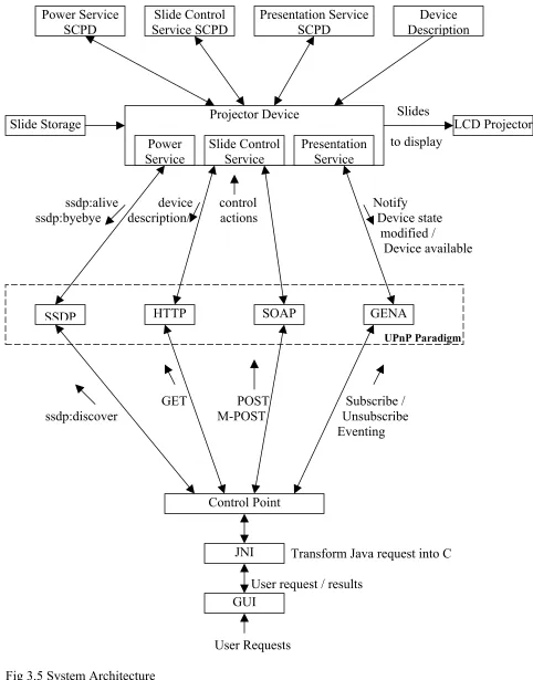
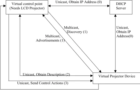
3.3 System Architecture
Figure 3.5 depicts the system architecture. It shows the interaction between various
components involved in the system. The projector device and the control point communicate
with each other via the UPnP paradigm. The various protocols provided by the UPnP paradigm
are used to pass the messages back and forth between the projector device and the control point.
The communication that takes place between the various components of the system is explained
using the following steps. These steps also explain which messages are passed between the
control point and the projector device. The format of all exchanged messages and actions is also
explained in these steps. The steps are:
• Discovery
• Description
• Control
• Eventing, and
Slides
to display
ssdp:alive device control Notify ssdp:byebye description/ actions Device state modified / Device available
GET POST Subscribe / ssdp:discover M-POST Unsubscribe Eventing
Transform Java request into C
User request / results
User Requests
Fig 3.5 System Architecture Power Service
SCPD
Slide Control Service SCPD
Presentation Service SCPD
Device Description
Slide Storage Projector Device
Power Service
Slide Control Service
Presentation Service
LCD Projector
UPnP Paradigm
SSDP HTTP SOAP GENA
Control Point
JNI
3.3.1 Discovery
From a device perspective, discovery governs the process of periodically advertising services
offered by the device and responding to queries for service by control point. For control points,
discovery allows interesting services to be discovered and used. When a device initializes and
joins a UPnP network, a series of advertisement messages are multicast that provide information
about device, any embedded devices and the services offered. The advertisements are sent using
“ssdp:alive” messages. When a UPnP device wishes to leave the network, it sends one
“ssdp:byebye4” message for each advertisement that was sent when it entered the network.
An example of “ssdp:aalive4” message, which is used to advertise the root projector
device is illustrated below:
NOTIFY * HTTP/1.1
HOST: 239.255.255.250:1900
CACHE-CONTROL: max-age=1800
LOCATION: http://137.30.123.107:5431/ProjectorDevDesc.xml NT: upnp:rootdevice
NTS: ssdp:alive
SERVER: Linux/2.4.2-2 UPnP/1.0 Intel UPnP SDK/1.0
USN: uuid:Upnp-Projector-1_0-1234567890001::upnp:rootdevice
The HOST header always contains 239.255.255.250:1900, which is a multicast address and port
reserved for the SSDP. The max-age field in the CACHE-CONTROL1 header is the
advertisement duration, in seconds. When this number of seconds passes without an additional
advertisement, control points should assume that the device has become unavailable. The NT1
(Notification Type) header contains a single Uniform Resource Identifier that identifies the entity
being advertised. The NTS1 (Notification Sub Type) header always contains “ssdp:alive” for
An example of a “ssdp:byebye” message, which is used to announce the demise of the
root projector device is illustrated below:
NOTIFY * HTTP/1.1
HOST: 239.255.255.250:1900
CACHE-CONTROL: max-age=1800
LOCATION: http://137.30.123.107:5431/ProjectorDevDesc.xml NT: upnp:rootdevice
NTS: ssdp:byebye
USN: uuid:Upnp-Projector-1_0-1234567890001::upnp:rootdevice
UPnP devices respond to control points explicitly searching for services. To search for
the service control points send “ssdp:discover” message. This message forces the appropriate
device to respond with the location of their description document. These protocols fall under the
Simple Service Discovery Protocol (SSDP) portion of the UPnP specification.
An example of a “ssdp:discover” message, which is used to discover the projector device(s) is
illustrated below.
M-SEARCH * HTTP/1.1 HOST: 239.255.255.250:1900 MAN: “ssdp:discover” MX: 10
ST: urn:schemas:upnp-org:device:projector:1
The MX1 field specifies the number of seconds the control point is willing to wait for a response.
The ST header defines the scope of the search. The value
“urn:schemas:upnp-org:device:projector:1” specifies the device type being searched.
3.3.2 Description
The information provided to a control point during the discovery is very minimal. The control
UPnP allows control points to obtain additional information about the device. This information is
contained in the XML description document for the root device, whose URL is discovered by the
control points at the time of discovery phase.
To obtain a device’s description document, a control point issues a standard HTTP GET,
using TCP over IP. The format of the message that is used in the projector system is shown
below.
GET ./web/ProjectorDevDesc.xml HTTP/1.1 HOST: 137.30.123.107:5431
ACCEPT-LANGUAGE: text/xml <<BLANK LINE>>
After “GET”, the path name component of the device’s description document is
specified. The host and port components are specified in the “HOST” component. The device’s
is due within 30 seconds. The response contains the XML description document in its body.
3.3.3 Control
Once a control point has obtained a device’s description document, it will typically want to
interact with the device, both to issue commands and to investigate an interesting device state.
Device interaction in UPnP is handled with Remote Procedure Call protocol called the Simple
Object Access Protocol. SOAP is based on extensions to HTTP, with actions specified in XML.
The SCPD for a service describes the actions that may be executed to interact with the service.
To cause a device to execute an action, control point sends a “POST” or “M-POST” message.
Control point may also request the value of specific state variables associated with a service
An example of the POST message for the projector system is illustrated below.
POST /upnp/control/power1 HTTP/1.0 CONTENT-TYPE: text/xml
SOAPACTION: “urn:schemas-upnp-org:service:PowerSwitch:1#PowerOn” CNOTENT-LENGTH: 221
HOST: 137.30.123.107:5431
<s:Envelope xmlns:s=”http://schemas.xmlsoap.org/soap/envelope/” s:encodingStyle=”http://schemas.xmlsoap.org/soap/encoding”> <s:Body><u:SetSlideRange
xmlns:u=”urn:schemas-upnp-org:service:SlideControl:1”/> <SlideRange>21</SlideRange>
</u:SetSlideRange> </s:Body>
</s:Envelope>
In the POST header, the path name component of the control URL for the associated service is
passed. The HOST1 header supplies the IP address and port of the control URL.
CONTENT-LENGTH1 tracks the number of bytes in the in the body of HTTP message. CONTENT-TYPE1
is always fixed, specifying that XML and utf-8 character encoding used in the body. The
SOAPACTION1 header contains a fixed prefix (“urn:schemas-upnp-org:service:”) and then
serviceType and actionName components. The serviceType defines the type of service to which
this action is addressed. This must match the serviceType appearing in the description document
for the root device and the actionName must match an action in the SCPD1 of the service.
The body of the message contains XML, which is enclosed in the tags <s:Envelope> and
</s:Envelope>. Two initial lines define the SOAP envelope schema and SOAP encoding schema.
In the <s:Body>, the name of the action and the service type are provided. These should match
the values provided in the message header. Subsequently, <argumentName>, </argumentName>
3.3.4 Eventing
The eventing mechanism in UPnP allows control points to receive asynchronous notifications
about interesting state changes in UPnP services. During control operations, control points
explicitly issue commands to change the state of UPnP devices and to query the values of state
variables. Eventing adds the ability to subscribe to a service and to learn of changes in the values
of state variables as they occur.
To subscribe to receive event messages, a control point sends a SUBSCRIBE1 messages.
To cancel a subscription, either a control point may let the subscription duration pass without
issuing a request for renewal, or it may explicitly cancel the subscription using an
UNSUBSCRIBE1 message. Requests to subscribe and unsubscribe to the service’s event
notifications are made to the event subscription URL in the device’s description document. All
subscriptions are leased, and they must be renewed periodically or they will expire. The protocol
that supports subscribing, unsubscribing and notifications in UPnP is called the General Event
Notification Architecture. GENA is an HTTP based protocol whose messages are sent over TCP.
An example of the SUBSCRIBE message in the projector system is illustrated below.
SUBSCRIBE /upnp/event/power1 HTTP/1.1 HOST: 137.30.123.107:5431
CALLBACK: http://137.30.123.107:5432 NT: upnp:event
TIMEOUT: Second-1800
The SUBSCRIBE message header follows the event subscription URL for the associated service.
CALLBACK provides URL on the control point where the service can send event messages. The
TIMEOUT1 is the requested duration in seconds. The response to the SUBSCRIPTION request
in the SID header contains a unique subscription ID associated with this subscription, which will
be used by control points to cancel or renew this subscription.
The format of the renew message is given below. It is similar to the SUBSCRIBE message
except the CALLBACK header is replaced by the SID header, which contains the subscription
UUID.
SUBSCRIBE publisherpath HTTP/1.1 HOST: publisherhost:publisherport
SID:uuid:subscription UUID
TIMEOUT: Second- requested subscription duration in seconds
<<BLANK LINE>>
The publisherpath corresponds to the event subscription URL (/upnp/event/power1), which is
obtained from the description document. The publisherhost and publisherport portion of the
message contain the host name and port components of the event subscription URL
(137.30.123.107 and 5431). The UUID contains the unique subscription ID.
The format of UNSUBSCRIBE message is given below. It is similar to the renew message
except it does not contain the TIMEOUT header.
SUBSCRIBE publisherpath HTTP/1.1 HOST: publisherhost:publisherport
SID:uuid:subscription UUID
<<BLANK LINE>>
Once a control point has subscribed, UPnP services are responsible for sending NOTIFY event
messages to the control point whenever state variables change. The format of the NOTIFY