SECOND LAW BASED ANALYSIS OF FLUID FLOW IN THE
REGENERATOR OF PULSE TUBE REFRIGERATORS
A. Jafarian, M. H. Saidi* and S. Kazemzadeh Hannani
Center of Excellence in Energy Conversion, School of Mechanical Engineering Sharif University of Technology, P.O. Box 11115-9567, Tehran, Iran [email protected] - [email protected] - [email protected]
*Corresponding Author
(Received: April 12, 2007 – Accepted in Revised Form: May 8, 2008)
Abstract As a necessary component, regenerator plays an important role in the refrigeration performance of the pulse tube refrigerator. The objective of this research is to investigate the flow characteristics in a porous regenerator of the pulse tube refrigerators, subjected to oscillating flow. The hydrodynamic and thermal behavior of the regenerator is investigated by considering porous media approach. The conservation equations are transformed by implementing the volumetric average scheme. Harmonic approximation technique is employed to derive an analytical solution. To investigate the system performance, second law analysis is performed in order to calculate the second law efficiency. The effect of geometry and operating key parameters on the regenerator performance are investigated as well. The developed model is able to predict the oscillating flow characteristics in the regenerator.
Keywords Oscillatory Flow, Porous Media, Entropy Generation, Regenerator
ﻩﺪﻴﻜﭼ
ﺩﺮـﮑﻠﻤﻋﺭﺩﻲـﺳﺎﺳﺍﻲﺸـﻘﻧ،ﻲﻧﺎﺑﺮﺿﻪﻟﻮﻟﻱﺎﻫﺯﺎﺳﺎﻣﺮﺳﺭﺩﻱﺪﻴﻠﮐﺀﺰﺟﮏﻳﻥﺍﻮﻨﻋﻪﺑﻲﺗﺭﺍﺮﺣﺏﺎﻳﺯﺎﺑ
ﺩﺭﺍﺩﺎﻫﻢﺘﺴﻴﺳﻦﻳﺍﻲﺗﺩﻭﺮﺑ
.
ﻭﻲﮑﻴﻣﺎﻨﻳﺩﻭﺭﺪﻴﻫﺭﺎﺘﻓﺭﻪﻟﺎﻘﻣﻦﻳﺍﺭﺩ
ﻳﺎﻣﺮﮔ ﻲ
ﻝﺪـﺒﻣﮏـﻳﻥﺍﻮـﻨﻋﻪـﺑﻲﺗﺭﺍﺮﺣﺏﺎﻳﺯﺎﺑ
ﻲﻣﺭﺍﺮﻗﻲﺳﺭﺮﺑﺩﺭﻮﻣﻞﺨﻠﺨﺘﻣﻂﻴﺤﻣﺭﺎﺘﺧﺎﺳﺎﺑﺪﻣﺁﺭﺎﮐﻲﺗﺭﺍﺮﺣ ﺩﺮﻴﮔ
.
ﻞـﺨﻠﺨﺘﻣﻂﻴـﺤﻣﺎﺑﻁﺎﺒﺗﺭﺍﺭﺩﺎﻘﺑﺕﻻﺩﺎﻌﻣ
ﻲـﻠﻴﻠﺤﺗﻞـﺣﻪـﺋﺍﺭﺍﻱﺍﺮـﺑﮏـﻴﻧﻮﻣﺭﺎﻫﻦﻴـﻤﺨﺗﺵﻭﺭﻭﻩﺪـﺷﻞﻳﺪـﺒﺗﻲﻤﺠﺣﻱﺮﻴﮔﻦﻴﮕﻧﺎﻴﻣﺵﻭﺭﺯﺍﻩﺩﺎﻔﺘﺳﺍﺎﺑ
ﻲﻣﻪﺘﻓﺮﮔﺭﺎﮐﻪﺑ،ﺕﻻﺩﺎﻌﻣ ﺩﻮﺷ
.
ﺭﻮﻈﻨﻣﻪﺑ
ﻡﺎـﺠﻧﺍﮏـﻴﻣﺎﻨﻳﺩﻮﻣﺮﺗﻡﻭﺩﻥﻮﻧﺎـﻗﺰﻴﻟﺎـﻧﺁﻲﺗﺭﺍﺮﺣﺏﺎﻳﺯﺎﺑﻲﻳﺍﺭﺎﮐﻲﺑﺎﻳﺯﺭﺍ
ﻲﻣﻪﺒﺳﺎﺤﻣﮏﻴﻣﺎﻨﻳﺩﻮﻣﺮﺗﻡﻭﺩﻥﻮﻧﺎﻗﻩﺩﺯﺎﺑﻭﻩﺪﺷ ﺩﺩﺮﮔ
.
ﺭﺎـﺘﻓﺭﺮـﺑﻱﺩﺮـﮑﻠﻤﻋﻱﺎﻫﺮﺘﻣﺍﺭﺎﭘﻭﻪﺳﺪﻨﻫﺮﻴﺛﺎﺗﻦﻴﻨﭽﻤﻫ
ﺖﻓﺮﮔﺪﻫﺍﻮﺧﺭﺍﺮﻗﻲﺳﺭﺮﺑﺩﺭﻮﻣﻲﺗﺭﺍﺮﺣﺏﺎﻳﺯﺎﺑ
.
ﻪﺼﺨﺸﻣﻲﻳﻮﮕﺸﻴﭘﻲﻳﺎﻧﺍﻮﺗﻪﻌﻟﺎﻄﻣﻦﻳﺍﺭﺩﻩﺪﺷﻪﺋﺍﺭﺍﻝﺪﻣ
ﻱﺎـﻫ
ﻲﻣﺍﺭﺍﺩﺍﺭﻲﺗﺭﺍﺮﺣﺏﺎﻳﺯﺎﺑﺭﺩﻲﻧﺎﺳﻮﻧﻥﺎﻳﺮﺟﻥﺍﺪﻴﻣ ﺪﺷﺎﺑ
.
1. INTRODUCTION
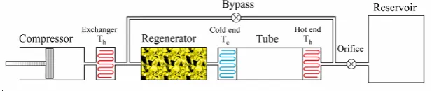
The use of very low temperatures for some product's applications such as in computer hardware, space, military, medicine, and electrical systems, requires the achievement of high performance cryogenic coolers. Pulse tube refrigerator as a reliable cryogenic cooler, contains no moving parts at its cold head, thus having considerable system advantages over most other types of cryogenic refrigerators such as Stirling and Gifford-McMahon. Figure 1 shows a schematic view of a double inlet pulse tube refrigerator. Generally, regenerator as a compact heat exchanger is a stainless steel tube filled with screen disks, or metal fibers. One end of the
Figure 1. A schematic view of a double inlet pulse tube refrigerator.
the double inlet pulse tube refrigerator was achieved by implementing a bypass between the central zone of the Pulse tube and that of the thermal regenerator. This improvement led to a new configuration named, Multi Bypass Pulse Tube Refrigerator [4]. Further efforts have been made to improve the performance of the key components of the pulse tube refrigerator, as well as the complete cycle.
The significant influence of oscillating flow characteristics in the regenerator of pulse tube refrigerators, on cooling performance has recently been recognized in several works. These efforts are categorized into three subjects, namely types of the materials, experiments and modeling.
Waele, et al [5] investigated the energy and mass conservation equations of the regenerator in the case of steady state pulse tube with a linear expression for flow resistance of the material. Before that, Xiao, et al proposed a model, neglecting conduction effects. In addition, Swift, et al and Roach, et al, presented their theory based on thermo-acoustic effect and phasor analysis, respectively [5]. Kashani, et al [6] proposed an optimization program for modeling of the pulse tube cryocoolers. They proposed a perturbation solution for the regenerator. Gary, et al derived REGEN 3.2 model for regenerator analysis. REGEN is a finite difference program and is used to study the effects of regenerator geometry. Gedeon presented Sage Pulse Tube Model in 1999 [7]. Sage is one of the most comprehensive models for cryocooler analysis. This model provides the user the ability to model the cryocooler and perform optimization analysis as well. In 1999, Lewis, et al [8] considered the effect of regenerator geometry on pulse tube refrigerator performance. Further more, Harvey, et al [9] in 2003, proposed a comparative evaluation of numerical models for cryocooler regenerators.
In spite of numerous mentioned efforts which have been performed to analyze and optimize the performance of pulse tube refrigerators, little work has been done to consider the dissipative phenomena in the regenerator which is the main source of entropy generation and lost work. In addition, due to the complexity of the oscillatory compressible flow equations in porous media, proposed numerical and CFD models, usually take considerable time to perform system optimization. Our objective in the present study is to achieve a better understanding of the hydrodynamic and thermal phenomena occurring in the regenerator of Stirling type pulse tube refrigerators. In this respect, the entropy generation phenomena are investigated considering a complete system of compressible oscillating flow equations in the porous regenerator.
Harmonic approximation technique is employed to derive an analytical solution. To determine the optimum operating conditions that maximize the second law efficiency, entropy generation phenomena is considered. The proposed model provides the ability to analyze the flow characteristics of the regenerator and perform rapid optimization based on second law of thermodynamics.
2. PHYSICAL MODEL AND GOVERNING EQUATIONS
Figure 2. A schematic view of the regenerator.
TABLE 1. Regenerator Physical and Operating Data.
Symbol Unit Value
p
C (Jkg-1k-1) 5225
s
C (jkg-1k-1) 368
dwire (mm) 5.6 E-2
Dh (mm) 9.194 E-2
D (m) 0.02 f (Hz) 10
g
k (Wm-1k-1) 0.1125
s
k (Wm-1k-1) 12
K (m2) 3.40 E-11
L (m) 0.2
Pm (bar) 12
H
T (k) 300
C
T (k) 70
Rg (Jkg-1k-1) 2100
Apass (m2) 37 %
δ (m) 0.001
μ (kgm-1s-1) 147.6 E-7 g
ρ (kgm-3) 3.8
ρs (kgm-3) 8000
ε 0.6950
the gas, an orifice, one bypass line and a reservoir. The regenerator geometry is a cylindrical domain with stainless steel wire screen mesh. Regenerator includes a solid and a fluid phase. The solid phase is assumed to be stainless steel packed wire screen with known thermal properties. The fluid phase is helium gas, which is assumed perfect. Figure 2 illustrates a schematic view of the regenerator. The working process of the pulse tube refrigerator is complicated due to the nature of unsteady, oscillating compressible gas flow. To trace the process, we treat it as a one dimensional, periodic, unsteady compressible flow. Following assumptions are introduced in our model as well:
• The outer sidewall of the regenerator is thermally insulated.
• The gas is ideal, and the flow of the gas is laminar.
• The regenerator radius is much smaller than the regenerator length. Thus, the entrance effects are neglected.
• The fluid phase satisfies the no-slip condition on the fluid-solid interface.
• Porosity is constant.
Under the above mentioned assumptions, the mass, momentum and energy conservation equations and equation of state in the case of one-dimensional flow in the x-direction become:
0 ) u g ρ ( . t
g ρ
= ∇
+ ∂
∂ r
(1)
) u g .(μ
) u . g (μ
3 1
P ) u u g (ρ
. t
) u g (ρ
r r
r r r
∇ ∇ + ∇ ∇ +
−∇ = ∇
+ ∂ ∂
(2)
0 ) g T g k g En u g ρ .( t
) g e g ρ (
= ∇ − ∇
+ ∂ ∂
r (3)
0 ) s T s k .( t
s T s ) C
ρ
( −∇ ∇ =
∂ ∂
(4)
) g e , g ρ ( f
P= (5)
) g e , g
ρ
( f g
T = (6)
Table 1 represents the physical properties and operating data of a typical regenerator, for which the analytical solution has been carried out.
and gas phase are transformed by implementing the volume averaging technique. Volume averaging is an analytical method, used to unite the microscale and macroscale characteristic of porous media flows. Appling the volume averaging technique, the system of equations leads to:
0 t u) g (ρ t g ρ = ∂ ∂ + ∂ ∂ (7) 0 u u K f C 2 ε 2 u g ρ u K με P) 2 u g (ρ x t u) g (ρ = + + + ∂ ∂ + ∂ ∂ (8) 0 ) g T s (T s A sg h ) x g T g k k N g En u g (ρ x t ) g e g (ρ = − − ∂ ∂ − ∂ ∂ + ∂ ∂ (9) 0 ) g T s (T s A sg h ε 1 ε ] x s T s τ s k [ x t s T ) s C ρ ( = − − + ∂ ∂ ∂ ∂ − ∂ ∂ (10)
A variety of models can be considered to provide insight into the mechanism of net energy transport in the regenerator. Constant Temperature Model (CTM), Local Thermal Equilibrium Model (LTEM) and Dual Energy Equation Model (DEEM) are extensively used to analyze the energy transport in the porous media.
In the present study, Local Thermal Equilibrium Model (LTEM) has been employed as a moderate technique to achieve an analytical solution. This model assumes that the heat transfer between the gas and the matrix is perfect. The consequence of the assumption is that there is an infinitesimal temperature difference between the gas and matrix. LTEM results in a single energy equation with a single temperature for both solid and fluid phases.
Under the above assumption, the conservation equations and equation of state are now written as: 0 t u) g (ρ t g ρ = ∂ ∂ + ∂ ∂ (11) 0 u u K f C 2 ε 2 u g ρ u K ε μ ) P 2 u g ρ ( x t u) g (ρ = + + + ∂ ∂ + ∂ ∂ (12) 0 ) x T s τ s k ε ε 1 x T g k k N Pu ( x x T v C u g ρ t T ] ε ε 1 s ) ρC ( v C g ρ [ = ∂ ∂ − − ∂ ∂ − ∂ ∂ + ∂ ∂ + ∂ ∂ − + (13) RT g ρ
P= (14)
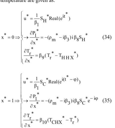
Boundary conditions on the velocity and temperature are given as follows:
⎪ ⎪ ⎩ ⎪⎪ ⎨ ⎧ − = ∂ ∂ − = ⇒ = ) HX H T r T ( H h x r T ε) (1 r k ) ωt i e ( Real H S ω u 0
x (15)
⎪ ⎪ ⎩ ⎪⎪ ⎨ ⎧ − = ∂ ∂ − ϕ − = ⇒ = ) r T CHX T ( C h x r T ε) (1 r k ) ) ωt ( i (e Real C S ω u L
x (16)
In the above system of equations, the thermal coefficient of heat transfer at the cold head and hot end of the regenerator are calculated from the following correlation proposed by Nika [12] in the case of packed wire screens used in the Stirling engine: 0.67 h 0.33Re g k h hD
Nu= = (17)
The permeability K, is expressed in terms of the pressure drop coefficient Cf and the Reynolds number based on hydraulic diameter, Reh [12].
f C h Re 2 h D ε 2
K= (18)
Where:
pass
and b c h Re a f
C = + (19)
The value of the coefficients a, b and c for different situations can be found in [12,13]. In the present work, these coefficients were chosen from the empirical correlation found by Tanaka [13] for the oscillating flow.
3. SOLUTION PROCEDURE
Harmonic approximation technique is employed to derive an analytical solution. In this method, variables are expressed as a sum of mean value plus higher order terms. The terms of higher order than first-order are neglected in this technique. A product of two first order terms is assumed to be a second-order, while a product of a mean value and a first order term still remains first order. The values of the gas velocity, density, temperature and pressure can be written as:
] ωt i (x)e 1 u [ Real t) (x,
u = (20)
] ωt i (x)e 1 ρ [ Real m ρ t) (x,
ρ = + (21)
] ωt i (x)e 1 [T Real m T t) x, (
T = + (22)
] ωt i (x)e 1 P [ Real m P ) t x, (
P = + (23)
Where, the real parts of the complex variables have been shown by the symbol Real. Substituting the above expressions into the system of equations and neglecting the second order terms, the following first order system of equations can be obtained:
0 x ) 1 u m (ρ ) iω ( 1 ρ = ∂ ∂
+ (24)
0 1 u K ε μ x1 P ) (iω 1 u m
ρ + =
∂ ∂
+ (25)
0 ) t ω i e 2 x 1 T 2 2 x m T 2 ( ) s τ s k ε ε 1 g k k (N t ω i e ) 1 u m P ( x t ω i e xm T u C 1 u m ρ t ω i e 1 T ] ε ε 1 s ) C (ρ u C m [ρ = ∂ ∂ + ∂ ∂ − + − ∂ ∂ + ∂ ∂ + − + (26) m T1 T m ρ m T g R 1 P 1
ρ = − (27)
Non-dimensional parameters are defined as:
L x *
x = , t*=ωt,
0 u
u *
u = ,
0 P
P * P = ,
0 ρ
ρ * ρ = ,
H T
T *
T = (28)
Where, u0, p0 and ρ0 represent the reference velocity, pressure and density respectively and are defined follows:
H S
ω
0
u = ,
H RT
m P 0
ρ = ,
2 2 0 u 0 ρ 0
P = (29)
Expressing the equations versus non-dimensional parameters leads to:
0 * x ) * 1 u * m (ρ 1 β i * 1 ρ = ∂ ∂
− (30)
0 * 1 u 3 iβ * x * 1 P 2 iβ * 1 u * m
ρ − =
∂ ∂
− (31)
0 ) * it e 2 * x * 1 T 2 2 * x * m T 2 ( * it e * x ) * 1 u * m (P 6 β * it e * x * m T * 1 u * m ρ 5 β * it e * 1 T 4 iβ = ∂ ∂ + ∂ ∂ + ∂ ∂ − ∂ ∂ − − (32) * m T * 1 T * m ρ * m T * 1 P 7 β * 1
TABLE 2. Dimensionless Parameters in Equations. Symbol Definition β1 Lω 0 u
β2 Lω
0 u 0
ρ 0
P
β3 ω
0 Kρ με β4 ) s τ s k ε ε 1 g k k (N ] ε ε 1 s C) ρ ( v C m [ρ 0
ωLρ
− +
− +
β5 )
s τ s k ε ε 1 g k k (N v C 0 u 0 ρ − + β6 ) s τ s k ε ε 1 g k k (N H T 0 u 0 P − + β7 H T g R 0 ρ 0 P β8 0 P ω 2 L 0 ρ
β9 (1 ε)
s k L H h −
β10 (1 ε)
s k L C h − β11 g k k N H T L 0 u 0 P Boundary conditions on the pressure and
temperature are given as:
⎪ ⎪ ⎪ ⎪ ⎪ ⎩ ⎪⎪ ⎪ ⎪ ⎪ ⎨ ⎧ − = ∂ ∂ − − = ∂ ∂ → = ⇒ = ) * X H H T * r T ( 9 β * x * r T * H S 8 β i ) 3 iβ * m (ρ * x * 1 P ) * it (e Real * H S 1 β 1 * u 0 *
x (34)
⎪ ⎪ ⎪ ⎪ ⎪ ⎩ ⎪⎪ ⎪ ⎪ ⎪ ⎨ ⎧ − = ∂ ∂ ϕ − − − = ∂ ∂ → ϕ − = ⇒ = ) * r T * CHX (T 10 β * x * r T i e * C S 8 β i ) 3 iβ * m (ρ * x * 1 P ) ) * i(t (e Real * C S 1 β 1 * u 1 *
x (35)
Dimensionless parameters in the above equations have been defined in Table 2.
According to the results found in the literature [5,15] and the analysis performed in the present work, the magnitude of the second term in the right hand side of the Equation 33 is negligibly smaller than the first term. This means that the first order density is significantly a function of first order pressure rather than temperature. Thus, the second term can be neglected.
Since the outer surface of the regenerator wall is taken adiabatic, the cycle averaged net energy flow through the regenerator is independent of longitudinal position. The net energy flow in the regenerator includes the enthalpy flow by the gas, heat conduction through the regenerator solid phase, heat conduction through the gas and the regenerator wall. This rule can be used to calculate the mean temperature along the regenerator. The following statement represents the net energy flow along the regenerator of the cryocooler.
] x g T c A pass A g k k N xw T w c, A w k xs T c )A pass A (1 s τ s k ) g T P C m [( H ∂ ∂ − ∂ ∂ − ∂ ∂ − − = & & (36)
differential equations in complex form is derived that should be solved to achieve the pressure gradient, density, velocity field and temperature distribution.
The steps which have been followed to achieve the solution are as:
• Substitute u1* and ρ1* from Equations 31 and 33 into the Equation 30 and solve the ordinary differential equation numerically to obtain the pressure amplitude, P1* as a function of longitudinal position, x.
• Put the first order pressure into Equation 31 to obtain the first order velocity, u1*.
• After substituting the first order velocity and the mean temperature distribution along the regenerator into Equation 32, solve the differential equation for the first order temperature numerically.
• Put the first order values obtained from solving the Equations 30-33 into the Equations 20-23 to complete the solution.
4. SECOND LAW ANALYSIS
One of the common criteria used to optimize the performance of the mechanical systems is the maximization of the 1st law efficiency. However, this parameter does not consider irreversibilities due to viscous and inertial effects, and heat flow. The second law efficiency can be defined by considering the rate of mechanical energy required to overcome the friction forces and all dissipative phenomena. The energy loss originated by the viscous dissipation and heat transfer are also included. The second law efficiency is defined by the following equation:
tot W
loss W 1 2nd
η
& &
−
= (37)
Where, W&totis the net work transfer rate to the gas to overcome the friction forces and dissipative phenomena. Symbol < > denotes integration over space and one period of time. The net work received by the working gas includes both acoustic
work and the work loss that should be compensated by the pressure generator in the system.
∫
= 02π dt
dt dV P 2π
1 ac
W& (38)
∫
= 02πT0Sgendt 2π
1 loss
W& & (39)
The local entropy generation rate and lost work are given by:
) x P ( g T
u 2 ) x
g T ( 2 g T
g k k N gen g, S
∂ ∂ − ∂ ∂ =
& (40)
2 ) x
s T ( 2 s T
s τ s k gen s, S
∂ ∂ =
& (41)
gen s, S
ε) (1 gen g, S
ε
gen sys,
S& = & + − & (42)
∫
=T0 0LSsys,genAcdx lost
W& & (43)
Since the second law efficiency considers the total dissipation produced by irreversibilities in the system, it can be employed to optimize the operation of the regenerator section of the pulse tube cryocoolers by looking for values of the effective parameters that minimize entropy generation and so maximize the second law efficiency for suitable operating conditions.
Non-dimensionalized statements of the entropy generation are as follows:
) * x
* P ( * g T
* u 11
β
2 ) * x
* g T ( 2 * g T
1 gen g, * S
∂ ∂ −
∂ ∂ =
& (44)
2 ) * x
* s T ( 2 * s T
1 gen s, * S
∂ ∂ =
& (45)
gen s, * S
ε) (1 gen g, * S
ε
gen sys, *
S& = & + − & (46)
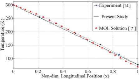
Figure 3. Regenerator temperature vs. position.
Figure 4. Inlet and outlet pressures vs. cycle time.
Figure 5. Helium density at the inlet and outlet of the regenerator vs. cycle time.
non-dimensionalized by the statements Nkkg/L2 and ksτs/L2, respectively.
5. RESULTS
To validate the proposed model, results have been compared with the experimental and numerical data in the literature. To perform the comparison between the results of the present model with that in the literature, two experimental and CFD works have been selected as target. The experimental work [14], deals with some experiments which have been conducted on the regenerator of a double inlet pulse tube refrigerator with operating pressure equal to 2.1 mPa, frequency of 16Hz and cold and hot temperatures of 77 k and 300 k, respectively. The CFD reference model is the Method of Line (MOL) solution, which has been applied to a typical regenerator with operating mean pressure of 3.1 mPa, frequency of 40 Hz and cold and hot temperatures of 70 k and 300 k, respectively [7]. Figures 3-6 show the results of the present work in comparison with those of the reference models. Figure 3 displays the temperature distribution along the regenerator. According to the above figure a good agreement between our solution and two reference works is observed.
Figure 4 monitors a small deviation between the outlet pressure profiles that is mainly due to the difference between the employed correlations of the inertia coefficient and permeability. Other vital parameters such as inlet and outlet density and velocity have been compared between the present solution and the CFD reference work, in Figures 5 and 6. In Figure 6 some deviations between the MOL solution and the present work are observed especially when the velocity is negative. These deviations are due to the effect of the last term in Equation 2, which has been neglected in our study as a second order term.
Figure 7 shows the velocity curves at different positions along the regenerator at frequency of 4Hz. According to the figure as the flow approaches the end of the regenerator, the velocity amplitude decreases. The effect of displacement length ratio, namely the ratio of the cold end
Figure 6. Regenerator inlet and outlet velocity vs. cycle time.
Figure 7. Velocity profiles in one period of oscillations at different locations along the regenerator.
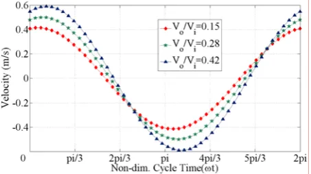
Figure 8. Velocity profiles at the middle of the regenerator for different velocity ratios.
Figure 9. Pressure variation in one period of oscillations at different locations along the regenerator.
Figure 10. Pressure amplitude vs. position for several aspect ratios.
end and the cold end of the regenerator, respectively. In the orifice pulse tube refrigerator by closing the orifice valve, Sr approaches zero, otherwise Sr < 1. In the present work we set the
ratio of the outlet velocity to the inlet by changing the amount of displacement length ratio, Sr. Three velocity profiles have been plotted at the middle of the regenerator at frequency of 4Hz in Figure 8. We have varied Sr from 0.2 to o.6 to set the velocity ratio as displayed in the figure. Figure 9 displays the pressure distribution at different locations along the regenerator at frequency of 10 Hz. According to this figure, as the flow approaches the cold end of the regenerator, pressure amplitude decreases.
Figure 11. Temperature distribution at the hot end of the regenerator for different values of velocity inlet.
Figure 12. Temperature distribution at the cold end of the regenerator for different values of velocity inlet.
Figure 13. Comparison of the first order temperature, density and pressure.
pressure amplitude decreases by increasing the amount of aspect ratio.
Figures 11 and 12 show the temporal variation of gas temperature for different values of the velocity inlet at frequency of 10 Hz. According to the figures, as the flow goes toward the cold end of the regenerator, temperature amplitude decreases. Besides, the temperature amplitude increases by increasing the amount of velocity inlet. In the regenerator, the temperature amplitude is very small in comparison with the average temperature. In fact, the large value of the solid matrix heat capacity results in very low amplitude.
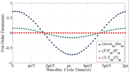
In Figure 13, the first order terms of the temperature, density and pressure have been plotted versus dimensionless cycle time in one period of oscillations. It is obvious that the amplitude of density is larger than the others. In addition, the amplitude of the first order temperature is negligibly smaller than the density and pressure amplitudes. This result approves the assumption that the first order density is more influenced by the pressure rather than temperature, used to simplify Equation 33.
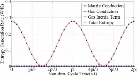
Figures 14 and 15 show the entropy generation rate of the gas, matrix and sum of the two in one period of oscillations at the regenerator inlet and outlet at frequency of 6 Hz, phase shift angle equal to pi/4 and aspect ratio of 10. According to the above figures, the amplitude of total entropy generation decreases as the flow approaches the cold end of the regenerator. The total entropy in the regenerator is produced by conduction in the solid matrix, conduction in the working gas and inertia term. The amplitude of the produced entropy, by conduction effect in solid matrix and working gas is negligibly smaller than inertia effect. However, here due to the effect of inertia term that overcomes the conduction effect, the amplitude of total entropy generation decreases as the flow goes toward the cold end. In fact, the amplitude of entropy generation by the inertia effect at the cold end is significantly smaller than that of the hot end. It should be noted that the total entropy generation is the summation of the entropy generation in the solid and gas phases considering the porosity coefficient.
Figures 16-18 show the cycle averaged entropy generation versus position for several values of essential operating parameters of the regenerator.
Figure 14. Gas, matrix and total entropy generation rate in one period of oscillations at the regenerator inlet.
Figure 15. Gas, matrix and total entropy generation rate in one period of oscillations at the regenerator outlet.
Figure 16. Total entropy generation vs. position at different frequencies.
Figure 17. Total entropy generation vs. position at different phase shift angles.
Figure 18. Total entropy generation vs. position for different aspect ratios.
the cycle averaged entropy generation along the regenerator. In Figure 17, cycle averaged entropy generation has been plotted versus position for different velocity phase shift angles at f = 6 Hz. As it is shown in Figure 17, no significant variation is observed in the cycle averaged entropy generation along the regenerator by changing the phase shift angle. Figure 18 shows that while the aspect ratio is equal to 10, the entropy generation rate is minimum in comparison with other geometries. Smaller aspect ratio, results in more entropy generation as Figure 18 displays.
6. DISCUSSION
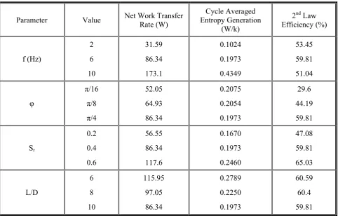
Table 3 represents the summary result of the parametric study, which has been performed in the
TABLE 3. Net Work Transferred to the Gas, Cycle Averaged Entropy Generation and Second Law Efficiency.
Parameter Value Net Work Transfer Rate (W)
Cycle Averaged Entropy Generation
(W/k)
2nd Law Efficiency (%)
f (Hz)
2 6 10
31.59 86.34 173.1
0.1024 0.1973 0.4349
53.45 59.81 51.04
φ
π/16 π/8 π/4
52.05 64.93 86.34
0.2075 0.2054 0.1973
29.6 44.19 59.81
Sr
0.2 0.4 0.6
56.55 86.34 117.6
0.1670 0.1973 0.2460
47.08 59.81 65.03
L/D
6 8 10
115.95 97.05 86.34
0.2789 0.2250 0.1973
60.59 60.4 59.81 efficiency has been displayed. According to the
above table, as the frequency of oscillation increases, the cycle averaged entropy generation increases while an optimum occurs in the second law efficiency at frequency of 6 Hz.
By increasing the velocity phase shift angle, the second law efficiency increases significantly, as Table 3 shows. Phase shift angle in the regenerator is caused mainly by the pressure drop and the influence of orifice at the hot end of the tube section. Displacement length ratio has been employed in the present model to set the ratio of the outlet velocity to the inlet. Around 38 % increase occurs in the second law efficiency when the value of displacement length ratio increases from o.2 up to 0.6. The influence of the regenerator aspect ratio on the flow field second law efficiency has been considered in Table 3 as well. No significant variation is observed in the second law efficiency as the aspect ratio changes.
7. CONCLUSION
valid and can be applied for different types of pulse tube refrigerators and especially for comparison of regenerator performance between various models such as orifice, double inlet, and multi bypass and multi stage systems.
8. NOMENCLATURE
A(m2) Area
C(J/kg.k) Specific Heat Capacity
Cf Inertia Coefficient
D(m) Diameter
e(J) Internal Energy
En(J/kg) Gas Enthalpy
h(W/m2.k) Heat Transfer Coefficient
H& (W) Net Energy Flow
k(W/m.k) Thermal Conductivity
K(m2) Permeability
L(m) Length
m& (kg/s) Mass Flow Rate
Nk Conductivity Enhancement
Nu Nusselt Number
P(bar) Pressure R(J/kg k) Gas Constant
Re Reynolds Number
Real Real Part
r(m) Tube Radius
S&(W/k) Entropy Generation Rate
S(m) Displacement Length
t(s) Time T(k) Temperature u(m/s) Velocity
V(m3) Volume
W& (W) Rate of Work Transfer
x(m) Axial Position
Subscripts
0 Reference State
1 First Order
ac Acoustic
c Cross Section
CHX Cold Heat Exchanger
C Cold End
g Gas gen Generation h Hydraulic
H Hot End
P Constant Pressure
s Solid
sg Solid to Gas
HHX Hot Heat Exchanger
m Mean Value
max Maximum pass Passage
r Regenerator
s Solid
sys System tot Total
υ Constant Volume
w Wall
Superscripts
* Non Dimensional
¯ Average Value
Greeks
ρ (kg/m3) Density
ω (1/s) Angular Velocity
μ (kg/m.s) Dynamic Viscosity
ν (m2/s) Kinematic Viscosity
δ (m) Wall Thickness
τ Solid Tortousity
ε Porosity
φ Phase Shift Angle
9. REFERENCES
1. Popescu, G., Radcenco, V., Gragalian, E., Ramany and Bala, P., “A Critical Review of Pulse Tube Cryogenerator Research”, International Journal of Refrigeration, Vol. 24, (2001), 230-237.
2. Mikulin, E. I., Tarasov, A. A. and Shkrebyonok, M. P., “Low Temperature Expansion Tubes”, Advances in. Cryogenic Engineering, (1984), 629-637.
3. Zhu, S. W., Wu, P. Y. and Chen, Z. Q., “A Single Stage Double Inlet Refrigerator Capable of Reaching 42 k”, ICEC Proc. Cryogenics, Vol. 13, (1990), 257-261. 4. Cai, J. H., Wang, J. J., Zhu, W. X. and Zhou, Y.,
“Experimental Analysis of Double Inlet Principle in Pulse Tube Refrigerator”, Cryogenics Journal, (1993), 522-525.
6. Kashani, A. and Roach, P. R., “An Optimization Program for Modeling Pulse Tube Coolers”, Advances in Cryogenic Engineering, Plenum Press, New York, U.S.A., Vol. 43, No. B, (1998), 1903-1909.
7. Harvey, J., “Oscillatory Compressible Flow and Heat Transfer in Porous Media-Application to Cryocooler Refrigerators”, Ph.D. Thesis, Georgia Institute of Technology, Georgia, U.S.A., (2003), 113-119.
8. Lewis, M., Kuriyama, T., Xiao, J. and Radebaugh, R., “Effect of Regenerator Geometry on Pulse Tube Refrigerator Performance”, Advances in Cryogenic Engineering, Plenum Press, New York, U.S.A., Vol. 43, (1998), 1999-2005.
9. Harvey, J., Desai, P. and Kirkconnell, C., “A Comparative Evaluation of Numerical Models for Cryocooler Regenerators”, Cryocoolers Journal, Kluwer Academic, New York, U.S.A., Vol. 12, (2003), 547-554. 10. Neveu, P. and Babo, C., “A Simplified Model for Pulse
Tube Refrigeration”, Cryogenics Journal, Vol. 40, (2000), 191-201.
11. He, Y. L., Huang, J., Zhao, Ch. F. and Liu, Y. W., “First and Second Law Analysis of Pulse Tube Refrigerator”, Applied Thermal Engineering, Vol. 26, (2006), 2301-2307.
12. Nika, Ph., Bailly, Y., Jeanot, J. C. and Labachelerie, M. D., “An Integrated Pulse Tube Refrigeration with Micro Exchangers: Design experiment”, International Journal of Thermal Science, Vol. 42, (2003), 1029-1045. 13. Tanaka, M., Yamashita, I. and Chisaka, F., “Flow and
Heat Transfer Characteristics of the Stirling Engine Regenerator in an Oscillating Flow”, JSME International Journal, Vol. 33, (1990), 283-289. 14. Ju, Y. L., Wang, C. and Zhou, Y., “Numerical
Simulation and Experimental Verification of the Oscillating Flow in Pulse Tube Refrigerator”, Cryogenics Journal, Vol. 38, (1998), 169-176.