VISUAL PROSTHESES
JEANDELBEKE CLAUDEVERAART
Catholic University of Louvain Brussels, Belgium
INTRODUCTION
Minute electrical stimuli delivered to the retina, the optic nerve, or the occipital cortex can induce light perceptions called phosphenes. The visual prosthesis aims at exploiting these phosphenes to restore a form of vision in some cases of blindness. Very schematically, a camera or a picture capturing device transforms images into electrical signals that are then adapted and passed on to some still functional part of the visual pathways, thus bridging the defective structures. The system has at least some parts implanted, including electrodes and their stimulator circuits. A photo-sensitive array in the eye could provide the necessary image input, but most approaches use an external minia-ture camera. Typically, the visual data handling requires an external processor and the power supply as well as the data are provided to the implant by a transcutaneous transmission system.
Despite a first pioneering attempt by Brindley and Lewin as early as 1968 (1) only very few experimental visual prostheses have been implanted in humans so far. The limited accessibility of the involved anatomical struc-tures, the poorly understood neural encoding, and the huge amount of information handled by the visual nervous system have clearly hampered a development that can not yet be compared with the far more advanced evolution of cochlear implants (see article on Cochlear Implants in this encyclopedia). The visual prosthesis is still at a very
early stage, exploring different methodological directions, and seeking minimal performances that would justify clin-ical applications in the most severe cases of blindness. The first fully fledged clinical study has yet to begin and the experimental character of existing systems limits all trials to a restricted number of well-informed adult volunteers.
Vision Basics and Retinotopy
A basic knowledge of the anatomy and physiology of the visual system is necessary for a proper understanding of the visual prosthesis in its various forms.
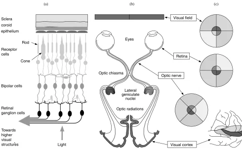
The eye can be compared to a camera with an adjustable optics including the cornea and the lens, focusing inverted images of the external world onto the retina. The retina is in fact a thin slice of brain that has expanded into the eye during the embryo development. It is made up of several cell layers. Among these, the photosensitive cells called cones and rods form the external layer with, as a result that light entering the eye has to cross the complete retina before to reach them (see Fig. 1c).
The 120 million or so photosensitive cells are not uni-formly distributed. Their density is highest at the fovea, a region that corresponds to the fixation point, near the center of the visual field. Cones outnumber the rods in the central retina and are the only kind of photosensitive cells at the fovea. They discriminate colors. Rods
predomi-nate at the periphery. These very sensitive sensors play a major role in night vision, but do not contribute to high resolution nor color perception. The cellular hyperpolari-zation generated by light impinging on the photoreceptors is carried over to other the neuronal cell layers ultimately connected to output layer represented by the ganglion cells. With the exception of the fovea (most central part) and especially in the periphery of the retina (i.e., of the visual field), there is a great deal of convergence and encoding of the visual signal that must be squeezed from the analog modulation of130 million photoreceptor potentials into the discharge bursts of little more than 1 million ganglion cells. Roughly, the bipolar cells represent the main con-verging vertical link between the photoreceptors and the ganglion cells. The horizontal cells at the junction between photoreceptors and bipolar cells and the amacrine cells at the junction between bipolar cells and the ganglion cells provide sideways connections. Functionally, the retinal network can be subdivided in a number of parallel channels each focusing on the transmission of one aspect of images. These include a color coding system and movement detect-ing circuits. Bipolar cells and ganglion cells also subdivide in ON OFF types. The ON cells increase their activity on exposure of the center of their receptive field to light while their ongoing firing slows down when light strikes in the periphery of that region. The OFF cells react in the opposite way. Ganglion cells also respond more or less
Light Towards
higher visual structures Sclera coroid
epithelium
Receptor cells
Rod
Cone
Bipolar cells
Retinal ganglion cells
Visual field
Retina
Optic nerve
Visual cortex Eyes
Lateral geniculate
nuclei Optic chiasma
Optic radiations
[image:2.612.57.547.377.679.2](a) (b) (c)
transiently. The result is a spatiotemporal retinal filter providing the optic nerve with a complex and still not well understood neural code Ganglion cell axons first runs over the inner surface of the retina to joint the optic nerve head located slightly nasally from the center of the retina. There, all ganglion cell axons join before to leave the eye and form the optic nerve.
In the orbit, the optic nerve is relatively slack, laying between extraocular muscles, fat tissue and various blood vessels and nerves. It is protected by a strong sleeve of dura mater as well as a very thin pia mater with cerebrospinal fluid in between. When the optic nerve enters the skull, it looses its dura mater sleeve, which now lines the inner surface of the skull. After a little>1 cm, the two intracra-nial optic nerves meet and exchange fibers at the level of the chiasma (see Fig. 1a). Ganglion cell axons of the nasal hemiretina or temporal visual field cross the midline and join the temporal axons of the other eye to form the optic tract. Foveal axons split into one branch toward each side. Some fibers (not represented) corresponding to accessory functions leave the mainstream visual pathway to reach the hypothalamus, pretectum and superior colliculus. The axons directly involved in vision end in the lateral genicu-late nucleus. This structure performs further signal pro-cessing and receives control signals from various parts of the brain. From the lateral geniculate nucleus, the visual information reaches the occipital lobe of the brain through the optic radiation. Interestingly, corresponding inputs from both eyes are arranged in close proximity, but remain segregated up to the level of the primary visual cortex. From there, signals corresponding to various aspects of the visual stimulus are dispatched to different brain locations for further processing.
Consequently, of the fiber exchanges at the level of the chiasma, except for the representation of the fovea, one visual cortex receives only information about the contra-lateral visual field. In addition, albeit with much distortion, cells of the visual cortex tend to retain the topological relationship of the retinal location from which they receive their input. The resulting point-to-point correspondence with the retinal locations, and hence the visual field is called retinotopy. Some form of retinotopy is found at most levels of the visual pathways up to the cortex (see Fig. 1b). Despite an obvious need for corrective remapping, retino-topy of the structure to be stimulated will be an essential consideration for the development of a visual prosthesis. Right from the level of the retinal ganglion cells on, reti-notopy nevertheless remains an approximation that does not take into account other significant aspects of the neural signal encoding.
Blindness
Under ideal conditions, the human minimum angle of resolution (MAR) is0.5 arc min (20/10 vision). However, the standard definition of normal visual acuity (20/20 vision) is the ability to resolve a spatial pattern separated by a visual angle of one minute of arc (4mm on the retina). The Snellen visual acuity measures the pattern recognition acuity as the ratiod/D, whereDis the distance at which a sign subtends 5 min of arc, anddis the distance at which
they can be recognized. Reference patterns subtend 5 min of arc at a distance of 60 m and have features of 1 min of arc, corresponding to the standard normal acuity. A visual acuity of 3/60 means that such a sign can only be recognized at a distance of 3 m. For practical purposes, the Snellen chart is made up of different sized letters such that the examination can be performed at a single distance. Because the normal acuity corresponds to 1 min of arc, the MAR value in arc minutes has the same numeric value as the reciprocal of the Snellen fraction.
However, sight is a multidimensional ability that can-not be measured by acuity alone. The effect of a visual field defect or a reduced sensitivity to light cannot be compared directly to acuity.
The International Statistical Classification of Diseases and Related Health Problems of the World Health Orga-nization (ICD-10) uses codes 1–5 to describe moderate, severe, profound, near total, and total visual impairments, respectively. Within that range, the label low vision (cate-gories 1 and 2 ) designates a visual acuity>6/18 (0.3), but <3/60 (0.05) in the better eye with optimal correction or a visual field between 10 and 308. The label blindness encom-passes categories 3–5. Code 3 corresponds to a visual acuity <0.05 on the Snellen scale for the best eye using appro-priate correction, or a central visual field diameter of<108 in its largest diameter. An acuity of<0.02 or a visual field <58is coded 4 (near total) while total visual impairment means deprived of light perception.
To measure a visual acuity in near total visual impair-ment, alternative methods are used including close range on the Snellen chart reading, finger counting, the detection of hand motion, or the perception of light.
Blindness can result from any cause potentially affect-ing the visual pathways: genetic abnormalities, infections, metabolic diseases, trauma, vascular deficiency, or cancer for example. In one subgroup, mainly represented by reti-nitis pigmentisa (RP), age related macular degeneration, and stargardt’s disease, it has been shown that blindness can result from a total destruction of the photosensitive cell layer while a proportion of other cells of the retina and the remaining of the visual pathways survive. The hereditary disease retinitis pigmentosa in particular, is a relatively frequent cause of severe and incurable blindness in devel-oped countries with a prevalence of 1 in 5000 (2).
disease. Early blindness type increased metabolic activity has been reported in cases where progressive total blind-ness occurred around the age of 10 (4). By contrast, late blindness features are observed when the first visual defect appears before the age of 8–12, but only evolve toward total blindness thereafter, or when vision is accidentally lost at the age of 12 or later.
A prosthesis implanted after the critical period is doomed to failure. Age of blindness onset, however, is not the only factor resulting in a deviant visual system. In diseases such as retinitis pigmentosa, the loss of photo-receptors itself results in important remodeling of the remaining retinal network (5), resulting in aberrant neural connections and shielding by scar tissue, all potentially limiting more or less severely the efficiency of a visual prosthesis.
History
The idea of an electrical treatment for blindness is perhaps as old as the discovery of electricity itself. The first real attempt to implant a visual prosthesis, however, dates back from 1968 (1). A set of 80 electrodes were implanted over the occipital pole of the cortex of a blind person. Each electrode could be activated transcutaneously by an equal number of implanted radio receivers. Small precisely located phosphenes were obtained, suggesting that a useful prosthesis could indeed become possible, but the subdural cortex surface electrodes had very high thresholds and did
not provide an adequate resolution. While intracortical electrode arrays were being developed using technologies derived from the semiconductor industry (6), it became clear that in terminal retinitis pigmentosa, a significant fraction of the ganglion cell population remains functional despite total blindness (7,8). In such cases, a visual pros-thesis interfacing with the surviving layers of the retina or with the optic nerve, all referred to as the anterior type could be as useful as the more complex cortical implant. As a result, starting around 1990, perhaps partially dragged by the success of the cochlear prosthesis, a renewed and still growing interest in visual prosthesis rapidly expanded worldwide.
Basic Theory of Operation of the Visual Prosthesis
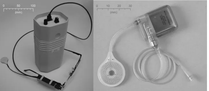
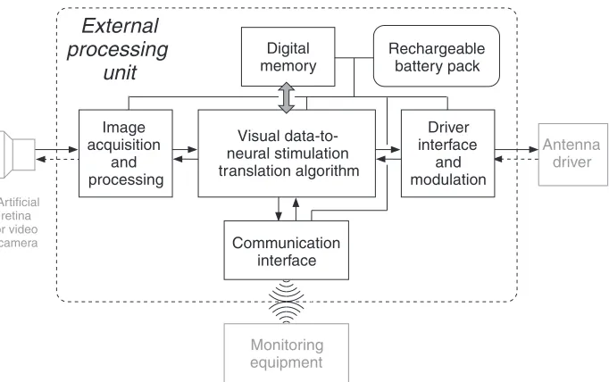
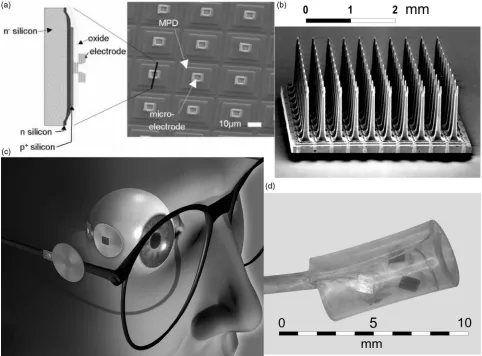
In all published visual prosthesis approaches, the visual system is very schematically seen as a transmission chain in which retinal image pixels are encoded into series of electrical pulses ultimately activating the visual cortex. The visual prosthesis is meant to replace or by-pass the defective link in the neural chain. At the cost of not using still functional body parts (eye optics, e.g.), most visual prosthesis designs replace the whole front end of the sensory chain, requiring only the prosthesis output to be connected to the nervous system (see Fig. 2). A picture of the external and implanted components of a prototype of the optic nerve visual prosthesis is given in Fig. 3 as an example.
External processing
Antenna
driver Neurostimulator
Neural interface
Artificial retina or video
camera
Implanted antenna
External
antenna
Implanted components
[image:4.612.114.502.66.175.2]From monitoring equipment
Figure 2. General layout of a visual prosthesis, with the external components on the left and the implanted components (shaded) on the right.
[image:4.612.54.417.570.729.2]Depending on the approach, the prosthesis sensors can be any imaging device from an implanted photoarrays (9) to a miniature cameras worn on a pair of glasses. In this last case, a small-size camera is also an asset for esthetical reasons.
A processor is necessary to transform the video images in properly encoded and modulated commands to the implanted stimulator (10). The prosthesis must allow real time object localization and identification. Visual informa-tion quickly represents a huge amount of data imposing high demands on the computational performances while the processor including its power supply, must remain easy to carry around. This portability often represents a tech-nological challenge by itself. Adaptability to new and rapidly emerging developments is also an essential requirement in this quite young technology. Transcuta-neous electromagnetic transmission of data and power using magnet fixated antennas is now standard for cochlear implants. This principle was already applied in a more primitive way by Brindley back in 1968 (1). He then solved the problems of parallel transmission through the implantation of an array of transmitters. Recent projects use combined power and data electromagnetic telemetry systems similar to those of the cochlear implant systems but with improved power and data performances.
Different Approaches
The neural interface typically represents the most critical and challenging component involved. In keeping with this, the different approaches to develop a visual prosthesis are often classified according to their connection point along the visual pathways: subretinal, epiretinal, transretinal, hybrid, optic nerve, cortex surface, or intracortical. The interface can be chemical or electrical. Until now, the chemical approach has been limited to some work on retinal devices. Many more projects use electrical stimula-tion through specifically designed electrodes.
Chemical Stimulation. The basic idea of this approach is to use neurotransmitters (L-glutamate, e.g.) or other
spe-cific chemicals that are known to activate neural or retinal cells. Directly over the retina, photochemical reactions (typically requiring ultraviolet, UV light) liberate active components from an inactive parent molecule or from ‘caging’ molecules (C60, fullerene) (11). The result is a direct translation of retinal images into a corresponding neural activation pattern. Alternatively, an electronically activated multichannel microfluidic device could deliver the needed chemicals locally and be used in a visual prosthesis as a substitute to electrodes (12). At present, most research efforts are still devoted to basic problems such as to reduce the required light energy level, biocom-patibility, transport of the chemicals and reservoir refill (13). In the future, however, chemical stimulation could have several advantages. There is no electrode corrosion. Stimulation selectivity can bear on the subgroups of retinal cells, and so mimic the physiological activation achieved by synaptic transmission. In addition, the proposed stimulat-ing electrodes can be made on soft materials supposed to be less damaging for the retina than electrode arrays (12).
Subretinal Implants. The most appealing aspect of the subretinal implants is that it exploits the supposedly healthy eye optics and interfaces to the visual pathways before any neural processing has blurred the neural code. The aim is indeed to replace the damaged photosensors by an array of passive miniature photosensitive devices trans-forming the retinal light image into local electrical stimu-lating currents. These currents would in turn activate the surviving neuronal circuits of the retina in keeping with the light intensity they receive, much in the same way as photosensitive cells do. The idea is straightforward and logical. Natural accommodation and physiological eye movements would remain functional. Very thin (100mm) flexible electrode construction and perforations allowing nutrient and other metabolic exchanges between the retina and the choroid could insure biocompatibility (14). The use of glycoprotein coating has been suggested to improve the biocompatibility of the components. Small implants can be quickly and securely trapped between the neural elements and the pigmentary epithelium, which seems to pump out this space (15). The light wavelength sensitivity of the microphotodiodes is in the 500–1100 nm range, which cor-responds reasonably well with the visible spectrum of 400– 700 nm.
Chow’s group developed a 25mm thick subretinal implant of 5000 subunits on a 2 mm diameter chip, enough to provide a tunnel vision of a little > 88. Such devices have been implanted in a number of retinitis pigmentosa patients. After 6–18 months, no significant side effect has been noticed and some patients reported a transient improvement not related to the implant position in the visual field. All the implants were electri-cally functional, but no visual response of the implant themselves was demonstrated (9). These devices are only powered by incident light but, as shown by Zrenner’s team, currents generated by microphotodiodes are by far too low to activate bipolar cells. Available devices, would require 12 klx (16) to do so while normal ambient light typically reaches 8 lx. An active amplification is therefore necessary, finally sharing with other approaches the need for an external power supply raising again the problems of bulkiness, heat dissipation, energy and data transmission.
image acquisition and processing sends data and power to the implanted electronics by telemetry. This device was implanted in several blind RP patient. Initial results seem encouraging (19).
The basic principle in most visual prosthesis approaches is that stimulation through a small electrode will result in the perception of a point-like phosphene of corresponding retinotopic localization. An array of such electrode contacts would produce a number of phosphenes that can be dis-tinguished by their location in the visual field. After cor-rection for any nonconformal localization, an image perception could then be obtained by activation of the corresponding pixel electrodes. It will be seen that this pixel phosphene method to selectively activate a subset of fibers or ganglion cells does not hold in the case of the optic nerve stimulation.
The Transretinal Approach. A transretinal approach (20) has also been suggested whereby a needle placed in the vitreous is used as a single cathode facing a mini-ature array of anodes slit under (or in the sclera), thus yielding a transretinal stimulation. Evoked potentials have been obtained in animals using eight contact on a 240.18 mm electrode with polyimide substrate. There is no indication yet as to which cells form the primary target.
The Hybrid Approach. The team of Yagi and Tano has started research to grow transplanted neural cells from a subretinal implant to the central nervous system using axon-guiding substrates. This approach could also be applied when ganglion cells are destroyed. This work remains very much preliminary and no results are avail-able yet.
The Optic Nerve Approach. A direct stimulation of the ganglion cell axons with an optic nerve electrode can be seen as an alternative to the epiretinal stimulation. The basic idea here is that the simultaneous activation of a number of contacts can focus the stimulation on a chosen subset of the axon bundle by controlling the applied electric field. As a result, electrode contacts around the nerve can yield a selective activation (21). The number of different fiber subsets that can be stimulated independently and thus the number of phosphene perceptions that can be obtained is much larger than the number of electrode contacts available. This principle could be applied to all electrodes carrying contacts at some distance from the target cells. Focal stimuli are thus generated serially by each multicontact activation instead of in parallel through individual contacts.
This concept has been validated in a human implanta-tion (22). The results confirm a retinotopic organizaimplanta-tion of the intracranial optic nerve and phosphenes are obtained with safe electric charges. Interestingly, due to the signal encoding in the optic nerve, phosphenes do not reproduce the distribution of the fiber activation and are much smal-ler than expected. Their position in the visual field can be controlled, which is of course essential in the prospect of the visual prosthesis development, making it possible to convey image information, even without resorting to more
complex selective stimulation schemes (e.g., superficial fiber blocking).
It has been suggested (23) that a penetrating electrode could increase the number of available independent responses, but the damage inflicted to the nerve has not yet allowed to validate such an alternative.
The first optic nerve electrode was implanted behind the orbit just in front of the chiasma. A new surgical technique has been developed to implant an eight contact electrode in the orbit. Avoiding intracranial surgery is certainly reas-suring for the patient, but the intraorbical approach is technically difficult and has several drawbacks. At that location, the optic nerve is indeed covered by the dura mater, which shields off the fibers from the stimulation and therefore results in higher thresholds. Also, somatic sensory nerve fibers as well as blood vessels are present in the dura mater, and eye movements could limit the stabi-lity of the electrode contacts. Nevertheless, the feasibistabi-lity of this approach has been demonstrated recently.
The Cortical Approach. The very first implanted human visual prosthesis prototype (1) included an array of 80 electrode contacts placed over the occipital cortex of a blind person and linked to an equal number of miniature transmitters placed under the scalp. High thresholds and poor selectivity have led to the conclusion that intracortical rather than cortex surface electrodes were necessary (24). Subsequently, a two-dimensional (2D) device known as the Huntington electrode (25) and a three-dimensionally (3D) structured, single plane, Utah electrode (26) were proposed for intracortical implantation. Resolutions of
400mm can be obtained (27) where the surface electrodes of Brindley could only resolve minimal distances of 2–3 mm. In an acute experiment, 38 intracortical microelectrodes have been implanted , for a period of 4 months in the right visual cortex of a human volunteer (6). Two-point resolution was about five times better than had typically been achieved with surface stimulation. All phosphenes were located in the left hemi-field with the majority above the horizontal meridian. There was a clustering of most of the phosphenes within a relatively small area of the visual space (6). As opposed to subdural electrodes, intracortical devices have the potential advantage to reach the hidden parts of the cortex in the depth of the calcarine fold corresponding to the big gap in the region of the horizontal meridian of the visual field as observed by Brindley.
Brindley himself stressed the important variability of the cortical maps among individuals. Individual mapping of each cortical implant is thus expected to be necessary. Biocompatibility is still a major point of concern, owing to the large number of electrode contacts and stimulator connections, especially for chronic human implantation. However, compared with the prechiasmatic approaches, the intracortical alternative would in the long run have the advantage of being applicable to many more conditions, not just diseases of the retinal photosensors.
Receptive field mapping was done using a memory saccade task (28). It is expected that such new animal psychophy-sical tests will compensate for the lack of a linguistic report and allow further developments in animals before finally turning to human trials.
ENGINEERING ASPECTS
The Hardware
Typically, the hardware of a visual prosthesis is composed of an external system and an implanted part. The external system (see Fig. 4) includes some image capturing device, an external processor and the external part of a transmis-sion unit. Implanted (see Fig. 5) are the other one-half of the transmission system, stimulators, and an electrode.
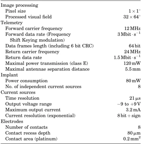
Depending on the approach, there are important variations on this basic scheme. In subretinal projects, a photosensor array implanted directly in the eye could replace the external camera. Some specifications of the example of the optic nerve prosthesis are given as an example in Table 1.
External Components
[image:7.612.218.559.62.276.2]The Image Grabber. A miniature video camera typically mounted on glasses provides the image capturing device of the visual prosthesis. A low weight camera with good esthetical appearance is of importance to the blind person and can be improved by miniaturization. It could further be stated that the most trivial imaging devices largely out-performs the needs of all present day visual prostheses (29). Nevertheless, a good image quality including some Figure 4. Detailed representation
of the external components of Figs. 2 and 3.
Antenna driver
Artificial retina or video
camera
Image acquisition
and processing
Visual data-to- neural stimulation translation algorithm
Driver interface
and modulation Digital
memory
Monitoring equipment Communication
interface
External
processing
unit
Rechargeable battery pack
Neurostimulator unit
Implantedantenna
Antenna interface
High voltage power supply
Demodulation - synchronisation Voltage regulator
Data in
Data out
Logic & memory
Regulated power supply
ADC DAC
Measure
470 nF
T O
E L E C T R O D E
A R R A Y +
E
[image:7.612.117.502.506.716.2]- E
standard correction features for luminosity compensation, autofocus, and avoidance of glare (e.g., could greatly sim-plify the later required image analysis). Later, when the usefulness of some image analysis procedures, such as edge enhancement or nonuniform resolution will have been demonstrated, it might become worthwhile to con-sider implementing such features in the front end hard-ware. The video camera would then be replaced by a specific imaging device that could evolve into a real arti-ficial retina.
In conditions, such as blindness, due to retinitis pigmentosa, the main target group for all prechiasmatic types of visual prosthesis, the optics of the eye can still be functional. In the subretinal approach, a photosensor array attached to the retina would transform the eye in an artificial video camera, preserving an essential function-ality of the natural eye, namely, gaze orientation . How-ever, in addition to biocompatibility requirements, mounting such a device as well as the necessary control electronics will not be easy (15). Provision must also be made to power the device and send its output signal to an external processor, all with an acceptable level of power dissipation (30).
The external processor. The bottleneck of all visual prosthetic systems is the rather limited quantity of infor-mation that can be handled by the neural interface. The amount of data to be transmitted must therefore be reduced by all possible means including image analysis. This topic is likely to become very important in the near future. Limiting images to black and white, thresholding, and edge detection are just preliminary steps. More sophis-ticated image processing techniques will have to be imple-mented. Therefore, powerful belt wearable processors will
be necessary to translate visual data to neural stimulation (see Fig. 4). Quite unlike the situation with cochlear implants, however, little is known about the precise encod-ing of visual information in the visual pathways and the first human implants will contribute to such knowledge (31) allowing more efficient algorithms to be developed.
Image processing can be subdivided in several steps including: analysis, selection, mapping, and encoding. The purpose of the image analysis is essentially to reduce the amount of visual data to be transmitted through the prosthesis. After an image data reduction step, a selection procedure should allow only the most important features to be send through. Mapping refers to the method used to establish a correspondence between selected image pixels or features and the phosphenes that can be generated. Finally, a control signals must be generated such that the implanted current sources will issue the intended stimulus. This last encoding step is entirely defined by the characteristics of the implanted device. Mapping on the other hand is linked to the neural code in the neural interface. Much of it is unknown and still requires experi-mental work with implanted volunteers. Later on, because of the anatomical variability, at least some individual remapping will be required before revalidation itself can be started with a visual prosthesis. Finally, except for the most basic and empirical aspects, image analysis and item selection will have to resort to further psychological studies on perception. Some of these studies could be done with healthy volunteers using virtual reality simulations.
A detailed description of one example of stimulation algorithm is given below. It should be stressed that a communication interface with the processor (see Fig. 4) is an important tool in the development and adaptation of the translation algorithm. Using monitoring equipment, the perceptions of volunteers can be explored and the system can be customized or adapted according to the findings.
Typically attached to the external processor, and prob-ably the major weight to carry along, are the power supply batteries. Note that all published visual prosthesis designs use externally powered implants. Therefore, current is also drawn from this main battery to provide power to the implant. The main specifications to be taken into account are the user friendliness of wearing and reloading the rechargeable batteries. Their size will be defined by a trade-off between weight and autonomy.
[image:8.612.52.294.86.333.2]The Transmission Unit. Electromagnetic telemetry is based on the classical cochlear implant design. It typically uses two similar antennas holding a small biocompatible (stainless steel encapsulated) magnet in their center. One of these is implanted under the scalp just above the mas-toid, behind the ear. The magnets maintain the external antenna over its internal counterpart. This turns out to be the most popular transcutaneous transmission system. The normal skin thickness separating the antenna coils is from 3.5 to 5 mm. However, just after surgery, swelling up to7 mm can be observed that can take>3 months to recede. During this period, the increased distance might cause malfunction of the antennas.
Table 1. Example: Main Specifications of the Optic Nerve Prosthesis
Image processing
Pixel size 118
Processed visual field 32648
Telemetry
Forward carrier frequency 12 MHz
Forward data rate (Frequency Shift Keying modulation)
3 Mbit s1
Data frames length (including 6 bit CRC) 64 bit
Return carrier frequency 24 MHz
Return data rate 1.5 Mbit s1
Maximal power transmission (class E) 120 mW Maximal antennae separation distance 5.5 mm Implant
Power consumption 80 mW
No. of independent current sources 8
Current sources
Time resolution 21ms
Output voltage range 9 toþ9 V
Maximum output current 3.2 mA
Current resolution (exponential) 8 bitþsign Electrodes
Number of contacts 8
Contact recess depth 80mm
A telemetry return channel from the implant to the external system is an important feature, providing acknowledgment signals as well as technical diagnostic and monitoring information. For example the output vol-tage of the implanted controlled current sources gives an indication about the proper operation of the system as well as an estimation of the electrode contact impedance. Also, a measurement of the supply voltage indirectly proves that the power transmission is working adequately.
Alternative antenna arrangements have been consid-ered. For example, as proposed by the Boston group (see Fig. 6), an external primary antenna or coil could be mounted on spectacles and the secondary coil could be implanted on the eye surface or in the anterior segment of the eye. Other transmission techniques exist. A trans-cutaneous socket on the head (32) has been used but it exposes the patient to severe infectious complications (33) and it is not really acceptable on esthetical grounds.
An all-in-the-eye alternative has been suggested whereby an infrared (IR) (820 nm) laser would transmit power and signal to an intraocular prosthesis through the transparent media of the eye. Data can be transmitted efficiently but heat dissipation in the implanted compo-nents is still not compatible with the power requirements of practical devices. Eye movements would also represent a tremendous challenge.
Implanted Components
[image:9.612.66.548.288.644.2]The Stimulator Case. The following description pertains to the intra-orbital optic nerve visual implant. The purpose of choosing one example is to provide a set of realistic numbers, but the principles apply to most visual prosthesis approaches. The antenna is connected to an 8 mm thick titanium case half engraved in the parietal skull. This neu-rostimulator hybrid circuit (see Fig. 5) contains the transmis-sion electronics as well as control logic circuits and the
current sources. This circuit occupies the major part of a titanium encasing is closed by a laser welded plate carrying 10 feedthrough connections. This number of feedthroughs is a main factor in determining the minimal size of the stimulator case. The metal encasing is internally connected as the common output reference electrode. A biocompatible polymer cap carries two connectors (a two-contact one for the antenna and an eight-contact connector to the electrode) and protects their junction to the feedthrough wires.
Each stimulator connection receive has two current sources, one for each polarity, as required for the app-lication of biphasic charge balanced pulses. As a rule, implanted current sources are coupled to the stimulation electrode through large output capacitors for safety rea-sons. These capacitors (470 nF), significantly contribute to the size of the implant.
In an attempt to reduce the chip size while providing a large number of channels, alternative designs (34) do multi-plex the output of a single stimulator to a number of electrode contacts instead of having one dedicated stimulator circuit for each contact. Also, the telemetry data rate could be reduced if less degrees of freedom were given in the stimulus definition. The possibility to modify the shape of each pulse individually does indeed require a high rate data transfer.
The Neural Interface or Electrode Assembly. Electrodes (see Fig. 6) are the most characterizing component of the different visual prosthesis approaches. They represent a rather critical and important component in electrophysiol-ogy applications (see the chapter on Bioelectrodes). In a nutshell, electrodes form the interface between the electric current carried by electrons along metallic conductors and the ionic conduction found in aqueous solutions, such as the body tissues. This potentially harmful transformation is chemical in nature, called a reduction reaction at the cathode and an oxidation process at the anode. A local pH change is induced, becoming more acid at the anode and more alkaline at the cathode. Of course, the exact nature of the chemical reactions taking place will be influenced by the electrode metal as well as the chemicals present in the solution, their concentrations and the applied potential among other factors. Irreversible chemical reactions cause corrosion and might severely limit the electrode lifetime. However, electric charge limits can be defined within which the chemical changes remain mostly reversible. Maximal values of 0.4 mC cm2 (35) are given in the literature for platinum and 4 mC cm2for iridium oxide (36). These metals are most often used in implantable electrode contacts. The reversible charge limits will preserve the electrode contacts, but they have no direct bearing on the potential damage to the living tissues being stimulated.
As a rule, biphasic stimulation pulses are used in implants in order to reduce the risk of deleterious effect. The cathodic phase is meant to activate the neural tissue while the anodic phase, often of smaller amplitude, but with a correspondingly longer duration, is supposed to compensate for the injected electric charge and thereby revert the local chemical changes. Because the currents are not uniformly distributed over a contact area, the electrode
geometry should also be taken into account in estimating the allowable charge limit.
The contact impedance or voltage–currents is an impor-tant characteristic of the electrodes. Dependent on a large number of factors, it is nonlinear and decreases with the current strength while increasing with the pulse duration. Table 2 gives average values as measured in the example of the optic nerve prosthesis. With epiretinal stimulation (37), using 1 kHz 10mA sine waves, impedance values are found to be distributed from<1 kV to 40 kV for the same contact area 0.2 mm2and larger values for 0.05 mm2 contacts. The higher values correspond to lower thresholds and are found when the contacts are closer to the retina.
The Prosthesis at Work
Phosphene Generation
Phosphene Description. A first step in the rehabilitation process with a visual prosthesis is to explore the available tools, that is, the identifiable phosphenes that can be generated by the system. A large number of stimulus variable (selected contact, pulse amplitude, pulse dura-tion, train duration and frequency) vectors are system-atically tested. The resulting perceptions must be carefully recorded for later use. A more straightforward relationship between the stimulation parameters and especially the contact being activated and the perceived phosphene localization can be expected with the retinal approaches. Still, however, the thresholds will have to be determined and data will be required to correct for the expected (18) mapping distortions.
With the optic nerve prosthesis, the phosphene dia-meters are variable from a point-like perception to>108. The distribution of these values has modal peaks2, 4, and 78depending on the stimulus parameters. The luminosity is most often reported as weak. Some phosphenes, espe-cially at the periphery of the visual field have the appear-ance of solid patches while others have variable textures, such as orderly arranged rows or columns of points or small lines. Phosphenes are colored sometimes with contrasting colors between texture elements and the local background. The global background of the visual field is usually described as black, but can sometimes be perceived as gray or slightly colored. Fluctuations of the diffuse background or spontaneous phosphenes occasionally hinder the percep-tion of induced phosphenes.
[image:10.612.316.558.77.131.2]In the optic nerve example, phosphenes remain located in a quadrant of the visual field that reflects the retinotopical position of the contact used. The center of the phosphenes is located peripherally if near threshold, high frequency and prolonged train stimuli are used and their position in the visual field takes on a more central position for stronger Table 2. End Pulse Voltage–Current Ratioa
Pulse Duration 42ms 342ms
Cathodic Current
0.4 mA 2.4 kV 5.0 kV
1.6 mA 2.3 kV 3.2 kV
stimuli, the strength being expressed as a stimulation to threshold current ratio. The most eccentric position that can be accessed by a given train stimulus is located nearer the center for short and/or low frequency trains (31). Phosphenes generated by single pulses are systematically located in the center of the visual field. It is thus possible to model and control the average phosphene center position in the visual field. Unfortunately, in the first implanted volunteer, phos-phenes could only be induced in a small region of the visual field (from 8.58on the left, to 11.58on the right, and from 68up to 478 down). This limitation is likely to be linked to the retinitis pigmentosa itself as it is known that only a fraction of the ganglion cells survive this disease (8) and the periphery is more affected than the central retina (38).
With retinal stimulation as well, it has been found that the form of the percept did not always match the stimula-tion pattern (18) despite the fact that small phosphenes could be obtained at visual field positions corresponding to the point of the retina being stimulated (18).
For all approaches, the phosphene position is clearly referred to retinal coordinates and therefore to the eye orientation at the time of stimulation. Any change in gaze direction or head movement preceding the stimulation will accordingly shift the perceived phosphene location. Thus, for every visual prosthesis with an image capturing device that is not attached to the eye, the users must learn to keep their eyes fixed in the orbit.
Phosphene perceptions are described as short-lived, flash-like. With repeated stimuli, flicker fusion has been found to occur8–10 Hz and is associated with a percep-tion threshold decrease. At very low repetipercep-tion frequencies (1–2 Hz) flashing phosphenes remain of stable brightness as long as the stimulation is maintained. By contrast, at higher frequencies, successive phosphenes are perceived a with decreasing brightness and disappear after 1–3 s.
Brindley (cortex, subdural stimulation) did not obtain a flicker fusion of cortical stimuli. Flicker fusion frequency was found to be similar for normal vision and for electri-cally generated perceptions using epiretinal electrodes (39). In this last approach, the perceived stimulus bright-ness increased with increasing stimulus rate as well as with increasing the stimulus current, which is not the case with optic nerve stimulation whereby the perceived phos-phenes become larger with stronger stimuli. This differ-ence might be related to the fact that the epiretinal stimulus can activate bipolar cells in addition to ganglion cells.
Simulation on Mathematical Models. Computational models play an important role in this kind of work. Numer-ical evaluation of the electric potential distribution in inhomogeneous and anisotropic media (volume conduction model), and of the resulting neural activation (neural membrane model), can provide a better understanding of the observed responses and provide a predictive design tool. As later confirmed experimentally (40), modeling the epiretinal stimulation has shown that cells or the initial segments have lower threshold than the passing axons (41). For pulses longer than 500ms, however, the bipolar cells become activated first. Confronting modeling results with experimental data has been useful in the
interpreta-tion of the results of optic nerve stimulainterpreta-tion studies as well, showing that the retinotopic extension of the perceived phosphenes is quite unlike the corresponding topologic distribution of the activated axons in the optic nerve.
Other techniques including an hybrid association bet-ween an adaptive neural network model and analytical expressions of physiological laws can describe the expected localization of phosphenes generated by optic nerve stimu-lation. These tools will in the future efficiently help to develop individual lookup tables derived from preliminary open loop testing sessions so that these can be kept as short as possible. Such tables or mapping systems are of primary importance for the development of a visual prosthesis, no matter the approach.
Stimulation Thresholds. Despite the functional impor-tance of the activation threshold, values applicable to a given situation are hard to find in the literature. A first reason for this is the lack of standardization. Current-controlled stimulators being used in most approaches, threshold current intensity could seem to be the logical variable to describe. However, as shown by the strength– duration relationship, the electric charge required for activation approaches a minimum asymptotically for short pulses, but increases very fast for pulses longer than the above the chronaxy value (see the article on Functional Electrical Stimulation). A threshold electric charge for realistically (in terms of the electronic circuits and tissue or stray capacitance) short stimuli can thus be seen as an appropriate expression, with the advantage that it directly relates to potential electrochemical damage to the elec-trode and surrounding tissue. The charge per unit area of electrode contact would be an even better characteristic value including the size factor as a minimal geometric parameter.
In an homogeneous medium, and at a distance much larger than the electrode contact diameter, the thresholds current is proportional to the square of the distance to target (Ith¼k ra), where a¼2. This power law can be seriously distorted in real tissues. For example in the retina (ganglion cell stimulation) exponent a can vary between 0.84 and 3.19 depending on electrode geometry and anatomical factors (29). Threshold values can further be expected to depend on factors such as the pulse shape, the nature of the primary target and the animal species.
The nerve membrane activation is not necessarily linked to the production of a cortical evoked potential neither the perception of a phosphene. For example, with optic nerve stimulation, long high frequency train stimuli have been found to yield much lower perception threshold than identical single pulses while in both cases expected to activate the axons at the same level (30).
Another aspect to be considered is that a disease, such as retinitis pigmentosa itself, can be responsible for an impor-tant increase in the stimulation threshold (42). The design of a prosthesis must therefore take this fact into account as well.
of 520mm (19). However, this threshold can vary between 24 and 702mA depending on the proximity to the retina (37). The same authors indicate that there is no simple relationship between the threshold and the electrode con-tact area. For the transretinal stimulation, a threshold value of 56mC cm2 is given, corresponding to a total charge of 28 nC (20). In the case of the optic nerve pros-thesis, an estimation for trains of 25 pulse (200ms dura-tion) at 200 Hz would yield a threshold of 60mA with the intracranial cuff (without dura mater) and 700mA with the intracortical cuff. The respective threshold charges are 6 and 70mC cm2. The corresponding chronaxy values are 130 and 192ms. Brindley (1) gives a value of 13 V on an impedance of 3 kV, yielding 4.3 mA to reach threshold with a good electrode driven at 30 Hz with 200ms pulses. This represents a charge of 860 nC. Thresholds down to 0.4 nC were obtained with 200mm2intracortical electrodes, which corresponds to 1.9mA for 200ms pulses at 200 Hz (24).
Stimulation Upper Limits. The upper limit of the sti-mulation range (44) is even more important to the designer than the threshold. The maximal current will indeed define the required minimal supply voltage as calculated from the expected load impedance. Any stimulus strength above a full activation of the target would represent a waste of the stimulator range and lead to unwanted physiologic response. However, despite the fact that they require higher current values, short stimulation pulses in fact activate the structures with lower charges, and therefore with a lower risk for local tissue and electrode damage. Unfortunately, the maximal current available is directly related to the size of the stimulator ASIC, which should be minimized, especially in a multichannel implant.
Increasing the electrode area to reduce the current density might seem to be an alternative. However, much of the gain in safe stimulus strength could easily be lost in the higher threshold characteristics of larger contacts that cannot be placed close to the target. Every approach will thus lead to a trade off between the stimulus strength required for proper activation, the safety limits and the size of the implant. In the example of the intracranial stimulation of the optic nerve, stable threshold levels have been observed for>6 years of compliance with an upper limit of 150mC (cm2 phase)1 for charge compensated biphasic pulses up to 50 Hz and <50mC (cm2 phase)1 at higher frequencies.
From Phosphene to Visual Perception (Stimulation Algo-rithm). Once phosphene perceptions can be elicited in a controlled way, one is left with the question as how to use them in order to convey visual information to the visual system of the blind person. In the optic nerve visual prosthesis example, a look-up table is first established using a phosphene position model as a mean to average and interpolate limited experimental data. From the col-lection of theoretically elicitable phosphenes, only those obtained with a charge density <300 nC/phase (0.2 mm2 contact area) are considered. Train stimuli longer than 40 ms total duration are excluded as well. The phosphene center has to be at least 18 of visual angle apart and, in
cases of choice, the phosphene produced with the lowest stimulus strength is selected. These criteria resulted in a set of 109 individually addressable phosphene with defined position. The portion of the visual field covered is limited to 148 horizontally and 418 vertically. Even within that region, there are holes where no phosphene can be obtained. In addition, the phosphene area is usually>18 and there is thus a clear overlap in the patches of visual field covered by neighbors. The usable look-up table is thus far from representing a complete set of nicely tiled point sized light perceptions covering the entire visual field.
Therefore, black and white images from a 1088 head-mounted camera are cropped and digitized to an array of 328648 field of view with one square degree pixels and 8 bit resolution. Next, thresholding is applied in order to further reduce the amount of visual information. In some tasks, image processing also includes edge detection. In real time, the processed image is then superimposed on the position coordinates of the phosphenes of the look-up table. If there is a coincidence between a phosphene position and any part of the image, the corresponding stimulation vari-able values are selected and send to the optic nerve stimu-lator. A list of the last 10 occurrences is continuously updated in order to avoid repeatedly inducing the same visual sensation when there are several coincident phos-phenes. The least frequently used coincident phosphene is always chosen as the next stimulus. When a single phos-phene is generated for each frame captured by the camera, 25 phosphenes can be induced per second.
The processor software and data can be accessed through a communication port (see Fig. 4) allowing to modify parameters, data tables, or the applied algorithms. For example, the random selection above could be replaced by a nearest neighbor selection or reference tables and parameters could be adapted to the perceptions reported by the volunteer. Some authors (45) have proposed a fitting optimization algorithm comparing the input images with the generated perception. This could work as an automatic processor training method. A major problem, however, is to make the subjectively perceived image available for com-parison with the input counterpart. It is likely that much
a prioriknowledge will always have to be included in any system. A large share of that knowledge is still not avail-able and will come, among others, from the contribution of first blind volunteers to the preliminary experiments.
From Image to Phosphene Production (Image Processing). No matter what encoding algorithm is used, it is obvious that the amount of information that can be transferred on by present day visual prosthesis prototypes remains extre-mely poor compared to real world images. Although some improvement can be expected from further interface devel-opments, severe image reductions will be unavoidable for quite some time.
symbols using a 44 pixel simulated prosthetic vision (48). Subject’s performances clearly increase with training.
It should be stressed, however, that quite unlike the image pixels used in simulations phosphenes are not iden-tical point-like ordered spots that neatly tile a surface. Also, these laboratory experiments only deal with experi-mental objects presented in an otherwise empty environ-ment. In the real world, subjects will first have to localize and segregate target objects by some preprocessing. How-ever, little has been achieved along these lines hitherto.
Vision Rehabilitation. The ultimate goal of a visual prosthesis is to rehabilitate a visually handicapped person. Results must therefore be evaluated from the blind per-son’s performances point of view and not in terms of device features. Issues, such as the number of available phos-phenes or their density, although contributing to the over-all performance, cannot be considered as representative of the value of a prosthetic system. Furthermore, isolated analytic characteristics, such as the visual acuity, often mean very little because they can be adjusted by acces-sories, such as a straightforward optical compensation.
A measurement of the performances will most reliably be obtained in laboratory conditions, but it is the useful-ness in real-life that will decide of the success of a pros-thesis. For mobility, the prosthesis will be judged against available alternative obstacle detectors and rehabilitation means, such as the long cane or the guide dog in mobility tasks. Stationary visual tasks, such as object localization, identification, and grasping as well as character reading, face recognition, and scene identification are less likely to be available through alternative means. In such tasks, the error rate and the time to task completion will probably be major criteria for acceptance.
Some evaluations of visual prosthesis implant proto-types have been published (19), showing that light and movement can be detected and simple shapes recognized. With the optic nerve implant, basic patterns formed by bars of 22320 mm and backprojected on a screen as black shapes against a white background can be recognized with the optic nerve prosthesis. The volunteer, sitting at a distance of 0.5 m from the screen, uses scanning head (and hence camera) movements to explore the pattern, then draws the perceived figure using aluminum rods. A learning effect can be demonstrated as well as an improve-ment of the results with the number of elicitable phos-phenes used in this test (49). A score of 87% of correct recognition is obtained with 109 phosphenes after training. Simultaneously, the task time decreased from>2 min to
53 s (49). With the same system and after substantial training, the volunteer was able to localize, discriminate, and grasp objects on a table in front of them. Three among six familiar objects lay each in one of the nine subdivisions defined on a table surface. Grasping a specified object among the three was systematically successful in 60 s. In both experiments, the scanning strategy probably explains the prolonged task completion times.
The emergence of multiple alternative designs and improvements for the prosthesis now call for evaluation standards. As suggested by these early results, these should include stationary tests (pattern identification,
figure orientation, object localization, object discrimina-tion, and grasping) as well as mobility trials (obstacle localization and avoidance, landmark localization, and identification). Evaluation of the usefulness of the visual prosthesis in a natural environment will be essential. Further down the road to improvement, face recognition, scene identification, and finally reading tests will perhaps also be considered but much better resolutions are still required (29).
HUMAN AND MEDICAL ASPECTS
Candidates for a Visual Prosthesis
No matter what approach is chosen, all visual prosthesis system require a functional visual brain to ultimately interpret their output. This means that, with today’s lim-ited performances, only people losing sight after the critical period of development can be considered as suitable can-didates.
Another selection criterion is the severity of blindness. As long as the performances of the systems are question-able, only totally blind persons should be considered as candidates. The risk of interfering with residual vision can indeed only be taken if the expected results are signifi-cantly better than the remaining visual abilities. In addi-tion, the evaluation of the rather limited performances of an implant could be obscured by any surviving visual functionality.
Other selection criteria are dependent on the chosen approach. All the prechiasmatic approaches (subretinal, epiretinal, optic nerve) require the survival of retinal gang-lion cells and their axons in the optic nerve. Terminal retinitis pigmentosa emerges as the condition most typi-cally fulfilling all the selection criteria. Except in cases of brain lesions, the cortical approach would be more gener-ally applicable, including in many cases of acute blindness where the psychological distress is usually more impor-tant. Finally, the individual’s general health should also be considered because satisfactory candidates are usually terminal cases of RP and therefore rather old while the implantation surgery requires a prolonged anesthesia.
A complete assessment procedure must precede implan-tation.
A standard ophthalmologic examination is a good start-ing point. Because of the chronic nature of the condition, the diagnosis should be checked according to up-to-date knowledge. Some candidates have not had an ophthalmo-logic investigation for many years and only know that they have an incurable eye disease. The blind patient could be unaware of some additional eye problem or other inter-fering condition. A proper evaluation of the total degree of blindness is necessary and objective tests, such a absent VEP and ERG, are very useful for comparison with the postimplantation evaluation.
pulses allow to generate a phosphene perception. In healthy subjects, for pulses >2 ms duration, phosphene perception occurs well before the stimulus can be felt. A threshold strength–duration curve (rheobase of 0.28 mA, chronaxy of 3.07 ms in sighted subjects) can show the perceptions to be genuine. Electrically evoked potentials (51) is an alternative technique that would not have to rely on the patient’s subjective perceptions. However, much of this added confidence is lost in important stimulation artifacts and the possible confusion with somatosensory potentials, especially in RP patients in whom thresholds are much higher. Some patients describe relatively abun-dant spontaneous phosphenes and these can be enhanced by the surface electrical stimulation. The same phenom-enon could completely jeopardize the working of a visual prosthesis and perhaps induce permanent unpleasant symptoms.
A psychological evaluation is essential as long as the procedure remains experimental. People do accept the idea of pioneering research, but quite rightly want to make sure they will not be misused as guinea pigs for the sake of science alone. The motivation put forward is to help in the development of treatments or simply for the satisfaction of an active contribution or to give their grandchildren a better chance in the frame of their hereditary disease. Esthetic aspects are questioned right from the first con-tacts. Visibility of a camera is a point of concern.
When the visual prosthesis will have become a clinical treatment, expectations will still have to be confronted with the systems limitations. Also, much attention should be paid to human factors, such as the impact of an implant on a person’s social integration.
Magnetic resonance imaging (MRI) is necessary for some visual prosthesis approaches. For example, the optic nerve size and diameter must be estimated on MRI images for an appropriate nerve cuff electrode to be selected for the optic nerve stimulation. The cortical approach might also benefit from a detailed anatomical image before surgery. An MRI examination could be dangerous and will yield very distorted images after implantation of a prosthesis. If for any reason, it is felt that such images will later be useful, then they should be acquired before implantation. Classical presurgical investigations including thorax X rays and an electrocardiogram (ECG) are standard presurgical procedures.
Surgical Methods
The surgical method is very specific to each of the approaches. The cortical approach can obviously start with a standard craniotomy. Implantation of intracortical electrodes, however, can require a more specific method including specifically designed instruments such as the pneumatic insertion device (52).
The optic nerve approach has resorted to two kinds of surgical methods, one to place the electrode intracranially just in front of the chiasma and the other to implant the electrode in the orbit. Basically, the intracranial method uses a standard pterional transsylvian approach. That is, after right temporo-fronto-parietal cutaneous incision and preparation of the temporal muscle, a craniotomy is
performed at the meeting line between the great wing of the sphenoid with the frontal, parietal and temporal bone (pterion). Opening the dura gives access to the sylvian fissure. From there, surgery further proceeds under a microscope to carefully dissect the arachnoid, opening the sylvian fissure until, in the depth, the optic nerve can be separated from it’s surroundings. Only minimal retraction of the basal posterior aspect of the frontal lobe is required. The electrode is then wrapped around the optic nerve and the lead suture to the dura.
The second surgical method involves the implantation of the spiral cuff electrode around the intracortical optic nerve. A medial orbital approach is used. After detaching the internal rectus to allow careful retraction of the eye, a thread can be inserted behind the optic nerve and be used to pull the cuff in place.
The electrode leads exit temporally from the skull (intracranial implant) or from the orbit (intraorbital implant) and run backward under the scalp toward the neurostimulator half buried in a recessed well made in the parietal bone. The neurostimulator is also connected to the antenna inserted under the scalp above the mastoid. The epiretinal system involves the implantation of a similar neurostimulator and wireless link unit as described above. The placement of the electrode is of course comple-tely different and works (19) as follows (19): The periocular space is reached through a lateral canthotomy. The cable and electrode are passed subconjunctivally all around the eye behind each of the four recti muscle insertions and then introduced into the eye through a 5 mm circumferential scleral incision placed 3 mm posterior to the limbus. Prior to the introduction of the implant, the majority of the vitreous gel is removed. The electrode array is the posi-tioned just temporal to the fovea and a single retinal tack is inserted through the electrode array and into the sclera. The attachment of the electrode to the retina is a main issue here. Several solution have been proposed including biocompatible glues, but recently developed types of min-iature nail-like devices called retinal tacks appear to work well.
At least two different subretinal electrode implantation methods have been developed (15). The ab interno techni-que, follows established vitroretinal and submacular sur-gery procedures. Surgical instruments are inserted into the eye. The vitreous body is then removed while the intraocular pressure is maintained with infusion. Finally, the retina is locally incised and the electrode array is inserted in the subretinal space using a special forceps. The ab externo implantation is designed to avoid damage to the internal structures of the eye. In this procedure, a flexible foil is inserted into the subretinal space through an incision in the sclera and choroid. The implant is then slit into a macular position along the guiding support foil. The path opened by this implantation can also be used for any required external energy supply leads.
Risks of Active Implants
of human trials have been described so far and most of them using methods too different to allow any globalization. A risk analysis will thus have to consider the various aspects of the implantation in the light of similar procedures. The required anesthesia is in itself a well known, low but finite life threatening factor linked to the duration of the procedure as well as the age and general condition of the volunteer. The surgery as such is often mentioned as the most feared aspect by patients. For most of the prechiasmatic approaches, only structures of a nonfunctional organ exposed and the worst failure would thus result in the loss of the possibility to implant a new prosthesis. Risks linked to the visual prosthesis itself can probably be considered to be similar to those for cochlear implants where they are reported to be negligible (53). In some approaches (intracranial optic nerve and cortical), a craniotomy is performed and electrodes are placed in the direct vicinity or in the brain. In such cases, the possibility of an infection or of an abnormal inflammatory reaction or even direct damage to the brain are potential hazards of major consequences. The possibility of an infectious metastasis around the foreign material must be borne in mind and is well known from passive implant applications. Similarly, experience with other active implants can help to evaluate the burden represented by possible electromagnetic interference, including airport or other safety systems, mobile tele-phone, interference between multiple implants and the fact that magnetic resonance imaging is no longer available to these patients.
The possibility of a total or partial failure of the implanted system must be considered. Again, however, useful figures, such as the typical lifetime of an implanted system and the percentage of failure in the initial period, cannot be estimated from the present heterogeneous and limited trials.
Heat production by implanted components and electro-chemical changes at the level of the electrode contacts are potential hazards insofar that they are not easy to predict because many factors are involved. Safety limits for functional electrical stimulation are difficult to estab-lish. Electrode failure or tissue damage are real risk factors. Also, unwanted stimulation of neighboring struc-tures can lead, for example, to pain or abnormal muscular contractions.
Living tissues can suffer from the activation itself. Axonal potentials are propagated at the cost of cellular metabolic energy. Too strong a functional demand on some structures could create a state of imbalance between the energy demand and supply, leading to cell dead. This type of limit will vary very much in different tissues. For example, peripheral motor axons typically discharge at frequencies 20 Hz and could be damaged by chronic stimulation at 50 Hz while 100 Hz is a typical frequency for afferent activities in the optic and cochlear nerves.
The electrical stimulation could also induce more subtle changes. For example, with cortical stimulation, there is a possibility to trigger repetitive firing and even epileptic fits. For high stimulation currents, Brindley has indeed described phosphenes lasting minutes after the stimula-tion has ended (1). Such after-discharges could be mini-mized by reducing the stimulus charge and avoiding prolonged regular stimuli (24).
Psychological complications represent another possible issue that should be monitored. Blindness is indeed a severe disability to which most of the implantation candi-dates as well as their surroundings have adapted over time. An effective prosthesis will shake this equilibrium as well as the person’s social insertion with consequences that could look paradoxical if only the technical success of the prosthesis was to be considered.
Ethical Aspects
With the project to fight one of the most basic human fears using high tech methods supposed to carry out miracles, the visual prosthesis is likely to enjoy a high profile to the layman and to trigger suspiciousness to scientists. This is thus a very emotional and sensitive subject that could be driven by many political and psychological forces alien to the interest of patients. That is why ethical questions should be dealt with most cautiously, especially in the early stages of development. Basic ethical rules still derive from the Nuremberg code of 1947. As a consequence of the Second World War, it appeared that compliance with national laws could some-times lead to unacceptable human behaviors. Some more fundamental ethical principles were raised above the law. This gave ethics a very special status. It is not a set of rules dictated by any form of power but pertains to every human being alike, above national or cultural differences (54). Ethics has neither organized a hierarchical structure nor an absolute reference. Progressively, from conferences to declarations, sets of principles gain universal acceptance. The World Medical Association Declaration of Helsinki, now at its fifth revision since 1964 (55), is most often considered as the main reference. Laws in democratic countries as well as many organization including scientific publishers enforce these basic principles. The European governments have extended these rules in the Convention on Human Rights and Biomedicine (56).
It is generally admitted that the implementation of ethical principles is very dependent on cultural factors. As a result, compliance of research projects with ethical principles is considered to be ideally insured by submission to an independent local ethical committee. National laws and institutional rules tend to organize the working of such committees. Typical questions investigated by these com-mittees are the quality of the information to the volunteer, signature of an informed consent, the risk/benefit ratio to the volunteer, the evaluation of motivations and free deci-sion as well as a specific insurance coverage including for removal of the implanted material if requested. An abso-lute preservation of the volunteers private life is a must usually requiring anonymity.
The initial development of a visual prosthesis requires a prolonged collaboration with volunteers. In that frame, it was found that the organization in collaboration with the Ethics Committee in charge, of within project meetings between members of the experimental team and represen-tatives of the volunteers could often be a very useful place to solve communication issues and take some consensus decisions with a volunteer.