Please cite this article as: G. Thakur, G. Singh, M. Thakur, S. Kajla,An Experimental Study of Nanofluids Operated Shell and Tube Heat Exchanger with Air Bubble Injection, International Journal of Engineering (IJE),IJE TRANSACTIONS A: Basics Vol. 31, No. 1, (January 2018) 136-143
International Journal of Engineering
J o u r n a l H o m e p a g e : w w w . i j e . i rAn Experimental Study of Nanofluids Operated Shell and Tube Heat Exchanger with
Air Bubble Injection
G. Thakur*, G. Singh, M. Thakur, S. Kajla
Department of Mechanical Engineering, Chandigarh University, Gharuan, Punjab, India
P A P E R I N F O
Paper history: Received 18 April2017
Received in revised form 13 October2017 Accepted 12 December2017
Keywords:
Shell And Tube Heat Exchanger Nanofluids
Heat Transfer Coefficient Nusselt Number
A B S T R A C T
Shell and Tube heat exchangers are the heat exchangers that are most widely used in industries and for other commercial purposes. There are many techniques that have been utilized to enhance the heat transfer performance of the shell and tube heat exchangers. Air bubble injection is one of the promising and inexpensive techniques that can create turbulence in the fluids resulting in to enhancement of heat transfer characteristics of the shell and tube heat exchangers. In this paper, experimental study of heat transfer characteristics have been done by injecting air bubbles at tube inlet and throughout the tube for 0.1%v/v and 0.2%v/v Al2O3 nanoparticle concentration. Results obtained at two different injection
points for both concentrations are compared with the case when no air bubble injection is done. The results showed the enhancement in the heat transfer characteristics with air bubble injection and volumetric concentration of nanoparticles. The maximum enhancement was found to be in the case where air bubbles are injected throughout the tube which is followed by the air bubble injection at the tube inlet and without air bubble injection. As the bubbles were injected throughout the tube, approximately 22-33% enhancement was observed. The overall heat transfer coefficient with injecting air bubbles throughout the tube showed an enhancement of about 12-23% and 14-25% for 0.1% and 0.2% of nanofluids.
doi: 10.5829/ije.2018.31.01a.19
NOMENCLATURE
d Diameter (m) µ Viscosity
h Heat transfer coefficient (W/m2K) Volumetric concentration
m Mass (kg) Subscripts
L Length (m) avg. Average
Nu Nusselt number bf Base fluid
Pr Prandtl number c Cold side
Q Heat Energy (joule) h Hot side
Re Reynolds number i Inlet
v Velocity (m/sec) LMTD Logarithmic Mean Temperature Difference U Overall heat transfer coefficient (W/m2K) o outlet
Greek Symbols np nanoparticle
Density (kg/m3)
1. INTRODUCTION1
From the recent studies, it has been found that the humans are exploiting limited sources of energy at an
*Corresponding Author’s Email:gt211991@gmailcom(G. Thakur)
techniques to enhance the thermal or heat transfer performance of heat exchangers[1].The world council has estimated that there would be around 50% rise in the energy demand in the coming future years that will be very difficult to achieve if the humans continue to use the energy resources at the present rapid rate[2]. It has been found that heat transfer has critical importance in the world of energy because if there would be more efficiency of heat transfer, then there would be more recovery of heat from the process under consideration. If there would be greater efficiency in recovering the heat, then there would be more energy savings. So, heat exchangers can be widely used to conserve energy by recovering more and more heat through heat transfer process and this conserved energy can be used for different purposes[3].
Shell and tube heat exchanger is one of the most commonly used heat exchangers in industrial applications with the ability to withstand high temperature (from -250°C to 800°C) and high pressure (up to 6000psi) of the working fluid. It is possible to enhance the thermal performance of shell and tube heat exchanger using distinct heat transfer enhancement techniques. One of the techniques that can be used to enhance the heat transfer rate between the fluids used in the shell and tube heat exchanger is air bubble injection technique. It is one of the passive techniques for heat transfer enhancement and very less utilized to enhance the heat transfer rate in heat exchangers. This technique, basically injects air bubble into the flowing fluid creating a turbulence in the flowing stream by reducing the skin friction drag near the wall. When bubble travels through the fluid, it creates a void behind which is to be filled by the liquid surrounding the air bubble, thus creating turbulence in the flowing fluid that ultimately results in the heat transfer enhancement.
Gabillet et al. [4]studied the effect of air bubble injection in turbulent boundary layers and reported an enhancement in turbulent kinetic energy and shear stress. Houshmand and Peles [5] experimentally studied the thermal performance in a micro channel taken into account the air bubble flow rate with water flow rate effect, and 16% enhancement was reported. Celeta et al. [6]studied the heat transfer characteristics of a heated channel by considering the effect of air bubble injection at its inlet and reported an enhancement of about 10 times in the heat transfer. Dizaji and Jafarmadar [7] studied the effect of air bubble injection on the Nusselt number of a double pipe heat exchanger and reported 6-35% enhancement in Nusselt number of a double pipe heat exchanger. Delaure et al. [8]studied the effect of ellipsoid air bubble rise in water on heat flux and found the enhancement in heat flux. Jacob et al. [9]compared the Reynolds stress and shear stress near the wall of single phase flow and two phase flow ( air bubble-water mixture) and reported that the two parameters have
fluid and reported an enhancement of about 25% in heat transfer coefficient and 20% penalty in pressure drop by adding small amounts of CuO nanoparticles into water as base fluid. Taheri et al. [23, 24]used hydraulic network modelling toevaluate the thermal performance of shell and tube heat exchanger and reported 25-48% enhancement of performance with different parameters. With addition of Al2O3 nanoparticles, heat transfer performance of vertical tube of radiator has enhanced up to 31% as compared to base fluid[25]. The objective of the present work is to study the performance of shell and tube heat exchanger with nanofluids and air bubble injection. Air bubble injection significantly improve the heat transfer performance due to turbulence in flowing fluid.
2. NANOFLUIDS PREPARATION
In present study, Al2O3 nanoparticles of size 20nm have been used. Nanofluids of 0.1% and 0.2% volume concentrations were prepared with two step method. The required volumetric concentration of nanoparticles is calculated by Equation (1):
bf bf
np np
np np
m m
m
(1)
The Al2O3 nanoparticles were purchased from Nanoshells, Derrabasi, India. A magnetic stir wasused to completely mix the nanoparticles with the base fluid. In order to remove the agglomerations, the nanofluids were placed in the ultrasonicator for about 2 hours for sonication. There was no need to add the surfactant to stabilize the nanofluids as the nanoparticles completely got mixed with the base fluid.
3. EXPERIMENTAL SETUP & WORKING PROCEDURE
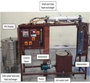
Figures 1 and 2 showthe actual picture schematic diagram of the experimental setup, respectively.
The experimental setup consists of test Section (shell and tube heat exchanger), hot water loop, water loop containing Al2O3 nanoparticles (0.1 and 0.2% volumetric concentration) and air injection system. Complete specifications of the test section are given in Table 1 and the components with the accuracy used for the various parameters during the experiment are given in Table 2. Four T-type thermocouples of an accuracy 0.1°C are installed at both the inlet and outlet of the shell and tube along with one the surface of the walls so as to help us to obtain wall temperature.
Figure 1. Experimental Set up
Figure 2. Schematic Diagram of Experimental Set up
TABLE 1.Specifications of test section
Dimensions Value
Length(mm) 600
Shell diameter(mm) 53 Tube inner diameter(mm) 10 Tube outer diameter(mm) 12.5
No. of Tubes 4
TABLE 2. Accuracy of components
Components Accuracy
Thermocouples ±0.1°C
Flow meter ±1%
PID ±0.25%
40, 50 and 60°C). The nanofluid is circulated at various mass flow rates (0.5, 1, 1.5, 2, 2.5,3 and 3.5 lpm) at a fixed temperature from the tube side. The mass flow rate of the hot water and nanofluid is controlled via two flow meters which are installed on both shell and tube side. The working accuracy of flowmeters is of about 1%. The accuracy and range of instruments is provided in Table 2. For the injection of air bubbles, an aquarium pump, which was able to inject air at the rate of 0.05833 kg/sec was used. For air bubble injection, a small diameter plastic tube with holes the tube was used. The calibration of instruments was the initial step of experimentation. The experimentation was divided into three different cases; a) the nanofluid flows on the tube side without air injection, b) second case in the experimentation was conducted with air bubbles injection at the inlet of the and c) the injection of air bubbles throughout the tube so turbulence can be generated. For the final analysis, average of seven readings at regular time intervals were taken.
4. DATA PROCESSING
Heat transfer characteristics such as heat transfer coefficient, overall heat transfer coefficient and Nusselt number are evaluated in order to analyze the effect of air injection technique applied to the shell and tube heat exchanger.
Reynolds number for the nanofluids is calculated using thefollowing equation:
𝑅𝑒 = 𝜌𝑣𝑑/µ (2)
The heat transfer coefficient is evaluated bythe following equation:
7 . 0 33 . 0 8 .
0 11
Pr Re 23 .
0
L d d
k
h i
i f
i (3)
The following equation is used to calculate the overall heat transfer coefficient:
LMTD O
avg T A
Q U
(4)
Equation (5) is used to evaluate logarithm mean temperature difference (TLMTD)
( ) ( )
ln
)) (
) ((
, , , ,
, , , ,
o c o h i c i h
o c o h i c i h LMTD
T T T T
T T T T T
(5)
The Nusselt Number is calculated by the equation given below as Equation (6):
k di h
Nu (6)
5. RESULTS AND DISCUSSIONS
5.1. Effect on the Heat Transfer CoefficientIt has been observed that the heat transfer coefficient increases with increasing Reynolds number. Air bubble injection at different points enhances the heat transfer coefficient as compared to the case without air bubble injection. This is due to the fact that the air bubble rises while flowing along the fluid creates void behind which is to be filled by the surrounding fluid creating turbulence in the flowing fluid, thus causing more heat to be transferred or higherheat transfer coefficient. The air bubble injection throughout the tube causes maximum heat transfer coefficient as compared to the other two cases. Moreover, rising bubbles create more turbulence than the bubbles along the fluid entering the tube which may be the reason for high heat transfer coefficient for air bubble injection throughout the tube than air bubble injection at the tube inlet. From Figures 3 and 4 it has been found that for 0.1% and 0.2% volumetric concentration of water based Al2O3nanofluid, the enhancement in the heat transfer coefficient on injecting air bubbles throughout is about 22-33% and 25-35%, respectively, while injecting air bubbles at the tube inlet gave 19-24% and 21-26% enhancement in the heat transfer coefficient as compared to without air bubble injection.
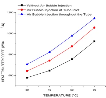
From Figures 5 and 6 it has been observed that at a constant flow rate of hot water and water based Al2O3nanofluid, with increase in inlet temperature, the heat transfer coefficient is enhanced.This is due to increase in temperature difference that causes more heat to be carried by the water based Al2O3 nanofluid, thus leading to high heat transfer coefficient. The case where air bubbles are injected throughout the tube gave maximum heat transfer coefficient with increase in the hot water temperature which is followed by the other two cases, i.e. with andwithout air bubble injection at the tube inlet. Since the thermal conductivity of nanofluids increase with increase in nanoparticles concentration, heat transfer coefficient for 0.2 % volumetric concentration nanofluid was found to be more than the 0.1 % volumetric concentration of water based Al2O3nanofluid in all three cases, i.e., without air bubble injection, air bubble injection at the tube inlet and air bubble injection throughout the tube.
0 8000 16000 24000 400
800 1200
HEAT
T
RAN
SF
ER
C
O
EF
F.
(W
/m
2-K)
REYNOLDS NUMBER without Air Bubble Injection Air Bubble Injection at Tube Inlet Air Bubble injection throughout the Tube
Figure 3.Heat transfer coefficient vs Reynolds number at 0.1% v/v
0 8000 16000 24000
300 600 900 1200
HEAT
T
RAN
SF
ER
C
O
EF
F.
(W
/m
2-K)
REYNOLDS NUMBER Without Air Bubble Injection Air Bubble Injection at Tube Inlet Air Bubble injection throughout the Tube
Figure 4.Heat transfer coefficient vs Reynolds number at 0.2% v/v
30 40 50 60
600 800 1000 1200
HEAT
T
RAN
SF
ER
C
O
EF
F.
(W
/m
2-K)
TEMPERATURE (°C) Without Air Bubble Injection Air Bubble Injection at Tube Inlet Air Bubble injection throughout the Tube
Figure 5. Heat transfer coefficient vs Temperature at 0.1 v/v
30 40 50 60
800 1000 1200
HEAT
T
RAN
SF
ER
C
O
EF
F.
(W
/m
2-K)
TEMPERATURE (°C) Without Air Bubble Injection Air Bubble Injection at Tube Inlet Air Bubble injection throughout the Tube
Figure 6. Heat transfer coefficient vs Temperature at 0.2 v/v
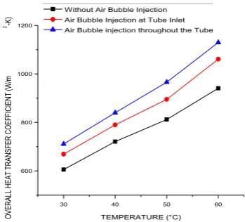
Furthermore, this enhancement increased upto 14-25% for the case with nanofluid containing 0.2% volumetric concentration of Alumina. The enhancement is due to the fact that as the bubbles injectedin the fluid, more turbulence is created which caused high heat transfer rate, thus eventually leading in to increase in the overall heat transfer coefficient. Figures 7 and 8 also revealed that the air bubble injection at the tube inlet enhanced the overall heat transfer coefficient by 8-21 and 10-24% with 0.1% and 0.2% volumetric concentration of Al2O3nanoparticles,respectively. This may be due to the void created by the air bubbles entering the tube inlet while flowing along the fluid which is to be filled by the surrounding fluid causing more heat to be carried out by the cooling fluid resulting in more overall heat transfer coefficient.
0 8000 16000 24000 0
200 400 600 800 1000
O
VER
AL
L
HEAT
T
RAN
SF
ER
C
O
EF
FI
CI
EN
T
(W
/m
2-K)
REYNOLDS NUMBER Without Air Bubble Injection Air Bubble Injection at Tube Inlet Air Bubble injection throughout the Tube
Figure 7. Overall heat transfer coefficient vs Reynolds number at 0.1% v/v
0 8000 16000 24000
300 600 900 1200
O
VER
AL
L
HEAT
T
RAN
SF
ER
C
O
EF
FI
CI
EN
T
(W
/m
2-K)
REYNOLDS NUMBER Without Air Bubble Injection Air Bubble Injection at Tube Inlet Air Bubble injection throughout the Tube
Figure 8. Overall heat transfer coefficient vs Reynolds number at 0.2% v/v
30 40 50 60
600 800 1000 1200
O
VER
AL
L
HEAT
T
RAN
SF
ER
C
O
EF
FI
CI
EN
T
(W
/m
2-K)
TEMPERATURE (°C) Without Air Bubble Injection Air Bubble Injection at Tube Inlet Air Bubble injection throughout the Tube
Figure 9. Overall heat transfer coefficient vs Temperature at 0.1% v/v
30 40 50 60
800 1000 1200
O
VER
AL
L
HEAT
T
RAN
SF
ER
C
O
EF
FI
CI
EN
T
(W
/m
2-K)
TEMPERATURE (°C) Without Air Bubble Injection Air Bubble Injection at Tube Inlet Air Bubble injection throughout the Tube
Figure 10. Overall heat transfer coefficient vs Temperature at 0.2% v/v
5.3. Effect on the Nusselt NumberNusselt number is found to increase with increase in the Reynolds number and air bubble injection. From Figures 11 and 12, it has been conferred that the injecting air bubbles throughout the tube enhanced the value of Nusselt number by 14-18and 15-20% for the two different concentrations of nanofluids i.e. 0.1% and 0.2% volumetric concentration of Al2O3nanoparticles in the base fluid compared withthe case without air bubble injection. The increase of Nusselt number is due to the fact that injection of bubbles increase in the flowing fluid, more turbulence is created in the flowing fluid containing air bubbles leading to more heat transfer coefficient which caused increased Nusselt number. Figures 11 and 12 revealed that the air bubble injection at the tube inlet also increasedthe Nusselt number by 9-14 and 10-15%, respectively with the use of water based nanofluids with 0.1and 0.2%
0 8000 16000 24000
30 60 90
NU
SSLET
NU
MBER
REYNOLDS NUMBER Without Air Bubble Injection Air Bubble Injection at Tube Inlet Air Bubble injection throughout the Tube
0 8000 16000 24000 20
40 60 80
NU
SSLET
NU
MBER
REYNOLDS NUMBER Without Air Bubble Injection Air Bubble Injection at Tube Inlet Air Bubble injection throughout the Tube
Figure 12. Nusslet number vs Reynolds number at 0.2% v/v
30 40 50 60
40 60 80
NU
SSELT
NU
MBER
TEMPERATURE (°C) Without Air Bubble Injection Air Bubble Injection at Tube Inlet Air Bubble injection throughout the Tube
Figure 13. Nusslet number vs Temperature at 0.1% v/v
30 40 50 60
50 60 70 80
NU
SSELT
NU
MBER
TEMPERTURE (°C) Without Air Bubble Injection Air Bubble Injection at Tube Inlet Air Bubble injection throughout the Tube
Figure 14. Nusslet number vs Temperature at 0.2% v/v
volumetric concentration of Al2O3nanoparticles when compared to the first case when no air bubbles are injected to the flowing fluid. Further increase in Nusselt number happened with increase in fluid inlet temperature as shown in Figures 13 and 14.
6. CONCLUSIONS
Air bubble injection is one of the inexpensive and passive techniques to enhance the thermal performance of a heat exchanger. The air bubble technique enhanced the performance of shell and tube heat exchanger. As the bubbles injected the throughout the tube, approximately 22-33% enhancement was observed followed by the injection of the air bubble at the tube inlet which showed an enhancement of about 19-24% as compared to without injecting any air bubble at a specific Reynolds number and for 0.1% v/v of Al2O3 nanoparticles. This enhancement further increased upto an enhancement of about 25-35% with 0.2% v/v concentration of nanofluids
The overall heat transfer coefficient with injecting air bubbles throughout the tube showed an enhancement of about 12-23 and 14-25% for 0.1 and 0.2% of nanofluids which is followed by the injection of the air bubble at the tube inlet which showed an enhancement of about 8-21% as compared to the case without injecting any air bubble at distinct Reynolds number.
The Nusselt number with injecting air bubbles throughout the tube showed an enhancement of about 15-20% which is followed by the injection of the air bubble at the tube inlet which showed an enhancement of about 10-15% as compared to the casewithout injecting any air bubble at a specificReynolds number.
7. REFERENCES
1. Kahrom, M., Haghparast, P. and Javadi, S., "Optimization of heat transfer enhancement of a flat plate based on pareto genetic algorithm", (2010), 177-190.
2. Ahmadzadehtalatapeh, M. and Yau, Y., "Energy conservation potential of the heat pipe heat exchangers: Experimental study and predictions", International Journal of Engineering, Vol. 25, No. 3, (2012), 193-199.
3. Cancan, Z., Yafei, L., Li, W., Ke, X. and Jinxing, W., "Review heat exchanger: Research development of self-rotating inserts in heat exchanger tubes", International Journal of Engineering-Transactions A: Basics, Vol. 27, No. 10, (2014), 15-26. 4. Gabillet, C., Colin, C. and Fabre, J., "Experimental study of
bubble injection in a turbulent boundary layer", International Journal of Multiphase Flow, Vol. 28, No. 4, (2002), 553-578. 5. Houshmand, F. and Peles, Y., "Impact of flow dynamics on the
heat transfer of bubbly flow in a microchannel", Journal of Heat Transfer, Vol. 136, No. 2, (2014), 022902, 1-8.
6. Celata, G., Chiaradia, A., Cumo, M. and D’annibale, F., "Heat transfer enhancement by air injection in upward heated mixed-convection flow of water", International Journal of Multiphase Flow, Vol. 25, No. 6, (1999), 1033-1052.
7. Dizaji, S., "Heat transfer enhancement due to air bubble injection into a horizontal double pipe heat exchanger",
International Journal of Automotive Engineering, Vol. 4, No. 4, (2014), 902-910.
9. Jacob, B., Olivieri, A., Miozzi, M., Campana, E.F. and Piva, R., "Drag reduction by microbubbles in a turbulent boundary layer",
Physics of Fluids, Vol. 22, No. 11, (2010), 115104.
10. Nandan, A. and Singh, G., "Experimental study of heat transfer rate in a shell and tube heat exchanger with air bubble injection",
International Journal of Engineering Transection B: Applications, Vol. 29, No., (2016), 1160-1166.
11. A.Nandan and G.singh, "Experimental study of heat transfer performance shell and tube heat exchanger with air bubble injection", International Journal of Engineering, Transactions B: Applications, Vol. 29, No. 8, (2016), 1160-1166
12. Kern, D.Q., "Process heat transfer, Tata McGraw-Hill Education, (1950).
13. Baghban, S.N., Moghiman, M. and Salehi, E., "Thermal analysis of shell-side flow of shell-and-tube heat exchanger using experimental and theoretical methods", International Journal of Engineering, Vol. 13, No. 1, (2000), 15-26.
14. Wei, X., Zhu, H., Kong, T. and Wang, L., "Synthesis and thermal conductivity of Cu2O nanofluids", International
Journal of Heat and Mass Transfer, Vol. 52, No. 19, (2009), 4371-4374.
15. Singh, G. and Sarao, T.P.S., "Experimental investigation of heat transfer characteristics of plate heat exchanger using alumina-water based nanofluids at different orientations", Indian Journal of Science and Technology, Vol. 9, No. 48, (2016), 1-14.
16. Singh, S., Singh, G. and Singla, A., "Experimental studies on heat transfer performance of double pipe heat exchanger with using baffles and nanofluids", Indian Journal of Science and Technology, Vol. 9, No. 40, (2016), 1-7.
17. Singh, G. and Sarao, T., "Experimental analysis of heat transfer and friction factor in plate heat exchanger with different orientations using al2o3 nanofluids", International Journal of Engineering-Transactions A: Basics, Vol. 29, No. 10, (2016), 1450-1459.
18. Thakur, M., Gangacharyulu, D. and Singh, G., "An experimental study on thermophysical properties of multiwalled carbon nanotubes", International Journal of Engineering, Transactions B: Applications, Vol. 30, No. 8, (2017), 1223-1230.
19. Priya, K.R., Suganthi, K. and Rajan, K., "Transport properties of ultra-low concentration cuo–water nanofluids containing non-spherical nanoparticles", International Journal of Heat and Mass Transfer, Vol. 55, No. 17, (2012), 4734-4743.
20. Sundar, L.S., Farooky, M.H., Sarada, S.N. and Singh, M., "Experimental thermal conductivity of ethylene glycol and water mixture based low volume concentration of Al2O3 and cuo
nanofluids", International Communications in Heat and Mass Transfer, Vol. 41, (2013), 41-46.
21. Ren, Y., Xie, H. and Cai, A., "Effective thermal conductivity of nanofluids containing spherical nanoparticles", Journal of Physics D: Applied Physics, Vol. 38, No. 21, (2005), 3958-3961.
22. Fotukian, S. and Esfahany, M.N., "Experimental study of turbulent convective heat transfer and pressure drop of dilute cuo/water nanofluid inside a circular tube", International Communications in Heat and Mass Transfer, Vol. 37, No. 2, (2010), 214-219.
23. Tahery, A.A., Khalilarya, S. and Jafarmadar, S., "Effectively designed ntw shell-tube heat exchangers with segmental baffles using flow hydraulic network method", Applied Thermal Engineering, Vol. 120, (2017), 635-644.
24. Jafarmadar, S., Tahery, A. and Khalilarya, S., "Hydraulic network modeling to analyze stream flow effectiveness on heat transfer performance of shell and tube heat exchangers",
International Journal of Engineering-Transactions C: Aspects, Vol. 30, No. 6, (2017), 904-911.
25. Sokhal, G.S., Gangacharyulu, D. and Bulasara, V.K., "Heat transfer and pressure drop performance of alumina–water nanofluid in a flat vertical tube of a radiator", Chemical Engineering Communications, No. just-accepted, (2017).
An Experimental Study of Nanofluids Operated Shell and Tube Heat Exchanger with
Air Bubble Injection
G. Thakur, G. Singh, M. Thakur, S. Kajla
Department of Mechanical Engineering, Chandigarh University, Gharuan, Punjab, India
P A P E R I N F O
Paper history: Received 18April 2017
Received in revised form 13 October 2017 Accepted 12December 2017
Keywords:
Shell And Tube Heat Exchanger Nanofluids
Heat Transfer Coefficient Nusselt Number ديكچ ه هلدابم نک اه ی ترارح ی هتسوپ و هلول ا ی هلدابم نک اه یی دنتسه هک هب روط هدرتسگ رد انص ی ع و د ی رگ اهدربراک ی راجت ی هدافتسا م ی دنوش . نونف سب ی را ی ارب ی ازفا ی ش درکلمع لاقتنا ترارح هلدابم نک اه ی ترارح ی هتسوپ و هلول ا ی دوجو دراد . رزت ی ق بابح اوه ی ک ی زا نونف ما ی راود هدننک و نازرا ق ی تم تسا هک م ی دناوت ثعاب ا ی داج گتفشآ ی رد ام ی تاع ،دوش هک رد تن ی هج ازفا ی ش و ی گژ ی اه ی لاقتنا ترارح هلدابم نک اه ی ترارح ی هتسوپ و هلول ا ی ار هب لابند دراد . رد ا ی ن ،هلاقم سررب ی برجت ی و ی گژ ی اه ی لاقتنا ترارح رد رثا رزت ی ق بابح اه ی اوه رد دورو ی هلول و زا رط ی ق هلول ارب ی 0.1 و 0.2 مجحدصرد ی
Al2O3