Induction Motor Drive using SPWM Fed Five
Level NPC Inverter for Electric Vehicle
Application
Rudra J. Kumar Praveen O.
PG Scholar PG Scholar
Department of Electrical & Electronics Engineering Department of Electrical & Electronics Engineering Mar Baselios College of Engineering and Technology,
Trivandrum, Kerala, India
Mar Baselios College of Engineering and Technology, Trivandrum, Kerala, India
Abstract
This paper presents an electric vehicle application which is powered by an induction motor drive which is fed by the SPWM triggered five level NPC inverter. Multilevel inverters can transfer high amount of power with low total harmonic distortion due to high number of switches each switch will take up voltage stress equally thus low chances of breakdown. Here we are using sinusoidal pulse width modulation technique which is simple and easy to work out in inverter triggering. Induction motor is a simple motor which is much reliable than all other motors, we are using a three phase induction motor which is a self-starting motor with low losses. Electric Vehicle is the load for induction motor, due to excessive pollution and depletion of natural resources these EVs are getting much popular. The Simulink model of overall system is done and the simulations are performed for various conditions using MATLAB/SIMULINK and the results are obtained and studied.
Keywords: Induction motor, Multilevel Inverter Neutral Point Clamped Inverter NPC, Sinusoidal Pulse Width Modulation, Electric Vehicle
_______________________________________________________________________________________________________
I. INTRODUCTION
In the last 20 years, the inverter has been widely in the AC drive fields due to the energy saving, reliability and performance indicators of great advantage. The huge demand of high power inverters in the industrial areas promotes the power electronic device capacity, voltage level and micro-electronic control technology to improve. Then all kinds of power inverter topologies are constantly evolving to transfer high amount of power without getting breakdown.
With the introduction of multilevel inverters in to the industry‟s most of the drives systems arefed by these multilevel inverters. The multilevel inverter produce a multilevel output voltage as the level of output voltage increases the total harmonic distortion factor reduces and the output more and more become pure sinusoidal wave. The major advantages of using multilevel inverters are they can transfer large amount of power than conventional Voltage Source Inverter. Three level and five level inverters are most widely used in industries for drive system application since they are simple and easy to switch. For switching of these multilevel inverters many PWM techniques are present such as Sinusoidal pulse Width modulation, Space Vector Pulse Width modulation etc.
Sinusoidal Pulse Width Modulation (SPWM) is very simple technique for switching of multilevel inverters. In this there is a carrier signal and reference signal by comparing these signals gating signals are produced and these gating signals are given the individual switches and corresponding output voltages are produced. SPWM technique can be increased to any level easily comparing to all PWM techniques.
Induction Motoris a high efficiency electrical machine which when working closed to its rated torque and speed, it is a self-starting motor. But, at light loads, no balance in between copper and iron losses, results considerable reduction in the efficiency. The part load efficiency and power factor can be improved by making the motor excitation adjustment in accordance with load and speed.
Induction Motor Drive using SPWM Fed Five Level NPC Inverter for Electric Vehicle Application (IJIRST/ Volume 4 / Issue 7 / 004)
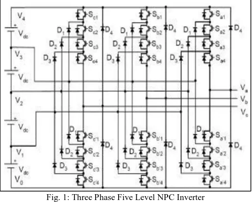
which is again subdivided by four capacitors into six levels [1]. The voltage across each capacitor is Vdc, and the voltage stress
across each switching device is very much limited to Vdc through the clamping diodes. Table1 shows switching states of 5 level
NPC inverter. State condition 1 means the switch is on, and 0 means the switch is off. Each phase has five complementary switch pairs. The complementary switch pairs for phase leg and are (Sa1, Sa„1), (Sa2, Sa„2), (Sa3, Sa„3) and (Sa4, Sa„4) [2]. Table also shows
that in a diode clamped inverter, the switches that are on for a particular phase leg is always adjacent and in series.
Fig. 1: Three Phase Five Level NPC Inverter
The advantages of NPC inverter are that the entire phases share a common dc bus, which minimizes the capacitance requirements of the inverter. For this reason, a back-to-back topology is not only possible but also practical for uses such as a high-voltage back-to-back inter-connection or an adjustable speed drive. The capacitors can be recharged as a group. Efficiency is high for fundamental frequency switching [3]-[5].
Table - 1
States of Switches of a Five-Level Inverter
Switching States
Output voltage Sa1 Sa2 Sa3 Sa4 Sa5 Sa6 Sa7 Sa8
off off off on on on off off -2V0
off off off on on off off on -V0
off off off on off off off off 0 off off on off off off off off 0 off on on off off off on off 2V0
on on on off off off off off V0
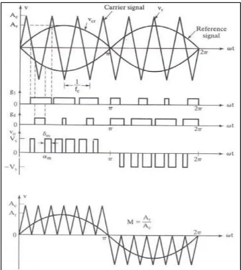
III. SINUSOIDAL PULSE WIDTH MODULATION (SPWM)
The width of all pulses the same as in the case of multiple PWM, the width of each is varied in proportion to the amplitude of a sine wave evaluated at the same pulse [6]. The distortion is reduced significantly compared to multiple PWM.
Fig. 2: SPWM Generating Gate Pulses
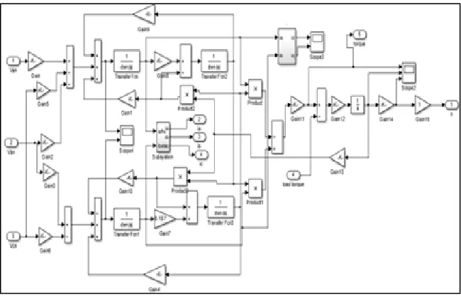
IV. INDUCTION MOTOR
The induction motor has a very wide range of industrial applications because of simple construction, ruggedness & low cost. These advantages are superseded by control problems when using in industrial drives with high performance demands. The dynamic model is used to for getting the transient and steady state behaviour of induction motor. Figure 3 shows the d-q model of induction motor [9].
The dynamic behaviour of Induction Motor can be with described with the equation of induction motor. A 3-phase winding can be reduced to 2- phase winding set by using this method. With the magnetic axis being formed in quadrature. The stator and rotor variable (voltage, current, and flux linkages) of an induction motor may rotate at an angular velocity or remain stationary, when transferred to a reference frame [10].
Induction Motor Drive using SPWM Fed Five Level NPC Inverter for Electric Vehicle Application (IJIRST/ Volume 4 / Issue 7 / 004)
V. EV DRIVE SYSTEM
The mechanism that transmits the power developed by the motor of automobile to the driving wheels is called the transmission system (or power train). In automobiles the differential allows the outer drive wheel to rotate faster than the inner drive wheel during a turn. A clutch is a mechanism which enables the rotary motion of one shaft to be transmitted at will to second shaft, whose axis is coincident with that of first. A gear is a rotating part having cut teeth which mesh with another toothed part to transmit torque. Geared devices can change the speed, torque, and direction of a power source.
VI. RESULTS AND DISCUSSIONS
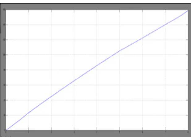
An induction motor drive for electric vehicle was discussed in the paper using five level NPC multilevel inverter with Sinusoidal pulse width modulation. This has been done using MATLAB/SIMULINK. When the induction motor torque reaches to 200 Nm then only the Electric vehicle starts to move and as torque values reduces the speed of electric vehicle increases to the 160 Km/hr.
Fig 4 represents the Simulink model of five level NPC multilevel inverter with SPWM, Fig 5,6,7 represents the Simulink model of one leg of five level NPC multilevel inverter, Simulink model of three phase induction motor and Simulink model of EV drive system. Figure 8, 9, 10 and 11shows the output voltage from five level inverter, stator current of induction motor, Torque and Speed of induction motor and the speed characteristics of electric vehicle in Km/hr.
Fig. 4: Simulink Model of Five Level NPC Multilevel Inverter with SPWM
Fig. 6: Simulink model of induction motor
Induction Motor Drive using SPWM Fed Five Level NPC Inverter for Electric Vehicle Application (IJIRST/ Volume 4 / Issue 7 / 004)
Fig. 9: Stator Current of Induction Motor
Fig. 10: Torque and Speed of Induction Motor
VII.CONCLUSIONS
The simulation of five level NPC multilevel inverter fed induction motor was carried out using Sinusoidal Pulse Width Modulation for electric vehicle application. The performance of the inverter, induction motor and drive system has been done using MATLAB/SIMULINK. From the results it is obtained as when starting torque is high then only vehicle will start to move and the torque of induction motor decreases the vehicle speed increases.
REFERENCES
[1] A.Nabae, I. Takahashi, and H.Akagi, “A new neutral-point-clamped PWM inverter”, IEEE Trans. on Ind. Appl., vol. 17, no. 5, pp. 518-523, Sept./Oct. 1981.
[2] J. Lai and F.Z.Peng, “Multilevel converters- a new breed of power converters”, IEEE Trans. on Ind. Appl., vol. 32, no. 3, pp. 509-517, May/Jun.1996. [3] G.S.Perantzakis, F.H.Xepapas and S.N.Manias, “A novel four-level voltage source inverter-influence of switching strategies on the distributionof power
losses”, IEEE Trans. on Power Electron., vol. 22, no. 1, pp. 149- 159, Jan 2007
[4] J.Meili, S.Ponnaluri, L.Serpa, P.K.Steimer and J.W.Kolar, “Optimized pulse patterns for the 5-level ANPC converter for high speed high power applications” in Proc. of IEEE IECON 2006, pp. 2587-2592.
[5] V. G. Agelidis, A. Balouktsis, I. Balouktsis and C. Cossar, “Five-level selective harmonic elimination PWM strategies and multi carrier phase shifted sinusoidal PWM: A comparison”, in Proc. of IEEE PESC 2005, pp.1685-1691. (Accepted by the IEEE Transactions on Power Electronics, 2007). [6] Akhila A, Nisha G .K, “Comparative Analysis of Capacitor clamped multilevel and Cascaded Multilevel Inverters Using SPWM,” International Journal of
Engineering Trends and Technology,vol.4,.no.1,pp.6-10,October 2016
[7] G. K. Nisha, S. Ushakumari and Z. V. Lakaparampil “CFT Based Optimal PWM Strategy for Three Phase Inverter,” IEEE International conference on Power, Control and Embedded Systems (ICPCES‟12), Allahabad, India, pp. 1-6, 17-19 December 2012.
[8] Akhila.A, Lekshmi.K.R, Nisha .G.K, “Analysis and Comparison of Flying Capacitor and Modular Multilevel Converters Using SPWM,”International Journal of Innovative Research and AdvancedStudies (IJIRAS), Vol.3, No.8, pp.352-357, July. 2016
[9] G. K. Nisha, Z. V. Lakaparampil and S. Ushakumari, “Performance Study of Field Oriented Controlled Induction Machine in Field Weakening using SPWM and SVM fed Inverters,” International Review of Modeling and Simulations, vol. 6, no. 3, pp. 741-752, June 2013.
[10] R.W. Menzies, P. Steimer, J.K. Steinke, “Five-level GTO inverters for large induction motor drives”, IEEE transactions on Industry Applications, Vol. 30, pp. 938-944, 1994.
[11] D. Lalili, N. Lourci, E.M. Berkouk, F. Boudjema, J. Petzoldt, M.Y. Dali, “A simplified space vector pulse widthmodulation algorithm for five level diode clamping inverter”, International Symposium on Power Electronics,Electrical Drives, Automation and Motion, pp. 21-26, 2006.