Modeling and Analysis of Propeller Shaft and Its
Coupling
S. Velmurugan R. Murasu
Assistant Professor Assistant Professor
Department of Mechanical Engineering Department of Mechanical Engineering CK College of Engineering & Technology Cuddalore,
Tamil Nadu
CK College of Engineering & Technology Cuddalore, Tamil Nadu
T. Vivek Asalan Assistant Professor
Department of Mechanical Engineering
CK College of Engineering & Technology Cuddalore, Tamil Nadu
Abstract
In Present scenario, any kind of Vehicle transmits Power from the drive systems to differential through the advent use of Drive shafts. Drive Shaft is a shaft for imparting torque from power source or prime mover to machinery. Nearly all of driveshaft is metal shafts or metal tubes that has special joint. The major failure occurred in drive shaft is due vibration, torsional stress and bending stress was experienced by driveshaft due to the weight of the car or misalignment of journal bearing. Drivers will lose control of their vehicle if the drive shafts failure occurs during high speed cornering. And also by varying the material we can reduce the weight of the rotating mass and increase the response. It allows more energy to go into rotating the tires instead of rotating dead weight. The above stated problem can be reduced by adopting the alternative material over it. Our project aims to reduce the weight of the drive shaft and conducting an analysis on it by varying the material in order to reduce the fuel consumption. We are making use of mechanical analysis tool “ANSYS” to conduct the analysis on propeller shaft and coupling. The analysis to be carried out may attain a well-developed Drive shaft which can be utilized in the recent automobile development domain of its first kind.
Keywords: Drive Shaft, Journal bearing, fuel consumption, mass, weight
_______________________________________________________________________________________________________
I. INTRODUCTION
Propeller Shaft
A driveshaft is the connection between the transmission and the rear axle of the car. The transmission is linked to the driveshaft by a yoke and universal joint, or u-joint, assembly. The driveshaft transmits the power to the rear end through another yoke and u-joint assembly. The power is then transferred by the rig and pinion or rear differential to the rear wheels.
The entire driveline of the car is composed of several components, each with rotating mass. The rule of thumb is that 17-22% of the power generated by the engine is lost to rotating mass of the drive train. The power is lost because it takes more energy to spin heavier parts. This energy loss can be reduced by decreasing the amount of rotating mass. Light weight flywheels and transmission gears, aluminum and carbon-fiber drive shafts, riffle-drilled axels, and aluminum hubs are all examples of replacement or modified parts used to reduce the amount of rotating mass.
Purpose of Drive Shaft
To reduce to the amount of rotating mass in the drive train, a light weight driveshaft will be used. The race car, pitted in an unending battle against the clock, is modified to squeeze every bit of horsepower out of it. The drag car is full of racing equipment, but currently has a steel driveshaft. The new drive shaft should take less 4 energy to spin therefore more of the energy produced by the engine can be transferred to the wheels.
In addition to increasing the efficiency, the composite shaft will be safer than a steel driveshaft. When a steel shaft fails, it projects shrapnel in all directions. There is also a possibility that the shaft may dig into the ground and catapult the vehicle into the air. When a composite shaft fails, it breaks into small fiber fragments posing no danger.
Functions of Drive Shaft
movement changes the angle between the transmission and the differential. The length of the drive shaft must also be capable of changing while transmitting torque. Length changes are caused by axle movement due to torque reaction, road deflections, braking loads and so on. A slip joint is used to compensate for this motion. The slip joint is usually made of an internal and external spline. It is located on the front end of the drive shaft and is connected to the transmission.
Composite
Composites consist of two or more materials or material phase that are combined to produce a material that as superior properties to those of its individual constituents. The advanced composite materials such as graphite, carbon, Kevlar and Glass with Suitable resins are widely used because of their high specific strength (strength/density) and high specific modulus (modulus/density). Advanced composite materials seem ideally suited for long, power driver shaft (propeller shaft) applications. Their elastic properties can be tailored to increase the torque they can carry as well as the rotational speed at which they operate. The drive shafts are used in automotive, aircraft and aerospace applications.
Carbon Fiber/Epoxy Composite
Carbon-fiber-reinforced polymer, carbon-fiber-reinforced plastic or carbon-fiber reinforced thermoplastic or often simply carbon fiber, or even carbon), is an extremely strong and light fiber-reinforced polymer which contains carbon fiber. The binding polymer is often a thermoset resin such as epoxy, but other thermoset or thermoplastic polymers, such as polyester, vinyl ester or nylon, are sometimes used.
The composite may contain other fibers, such as aramid e.g. Kevlar, Twaron, aluminum, or glass fibers, as well as carbon fiber. The properties of the final CFRP product can also be affected by the type of additives introduced to the binding matrix (the resin). The most frequent additive is silica, but other additives such as rubber and carbon nanotubes can be used. CFRPs are commonly used in the transportation industry; normally in cars, boats and trains, and in sporting goods industry for manufacture of bicycles, bicycle components, golfing equipment and fishing rods.
II. EXPERIMENTAL SET UP
Design of Shaft:
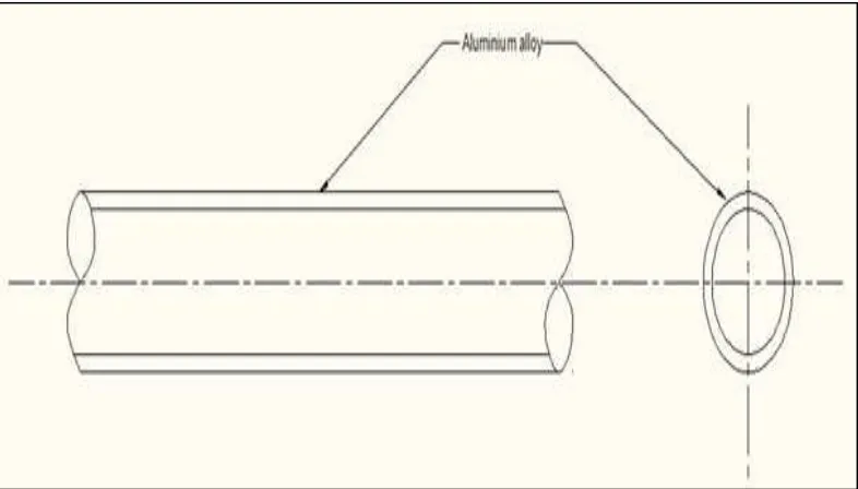
The figure 2.1 (a) and 2.1 (b) shows the design of the existing Aluminium drive shaft and the proposed carbon fiber drive shaft.
Fig. 2.1 (b): Schematic diagram of carbon fiber / epoxy drive shaft
Mechanical Properties:
The table 2.1 (a) and 2.2 (b) shows
The material property of aluminium alloy and carbon fiber/epoxy. Table - 2.1 (a)
Material property of aluninium alloy
MECHANICAL PROPERTIES UNITS ALUMINIUM Young’s modulus MPa 71000
Shear modulus MPa 26692 Poisson ratio --- 0.33
Density Kg / m³ 2770 Shear strength MPa 26692
Bulk modulus MPa 69608 Tensile yield strength MPa 280 Tensile Ultimate strength MPa 310 Compressive Yield Strength MPa 280
Table - 2.2 (b)
Material property of Carbon fiber/epoxy
MECHANICAL PROPERTIES UNITS CARBON FIBER/EPOXY Young’s modulus MPa
Shear modulus MPa Poisson ratio --- Density Kg / m³ Yield strength MPa Shear strength MPa Bulk modulus MPa Tensile yield strength MPa Tensile Ultimate strength MPa Compressive Yield Strength MPa
Analysis Procedure on Ansys:
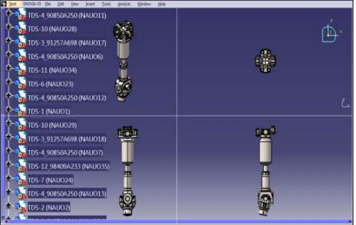
1) The 3D model is created in CATIA as per the calculated dimensions of shaft and coupling assembly in design calculation part.
2) This model has to be analyzed in ANSYS Software for the structural analysis. 3) File → Import→ IGES→ Model.igs.
4) Ansys workbench → read input from → select igs file → generate → export. 5) Preference → Structural → OK.
6) Preference→ Element type→ Add/Edit/Delete → Add→ Solid 185→Elastic. 7) Preference → Real constants→ Add/Edit/Delete→ Add .
10) Preference→ Loads → Define load→ Apply → moment value→ Structural → Displacement→ On line→ Pick line→ All Dof = 0.
11) Preference→ Loads→ Define load→ Apply→ Structural → Force/Moment→ On nodes → Define load→ Apply→ Moment = 250Nmm.
12) Solution→ Solve→ Current LS→ solve
13) General post processing→ Plot results→ Contour plot→ Nodal solution→ Stress→ Vonmises Stress→ Ok 14) General post processing→ Plot results→ Contour plot→ Deform → Under form shape → ok
III. MODELLING AND ANALYSIS OF DRIVE SHAFT
Modelling of Drive Shaft:
The modelling of drive shaft is done using CATIA software because it is one of the most widely used software for automobile parts modelling.
Fig. 3.1: Drive shaft (CATIA modelling)
The above image shows the front view of the assembled drive shaft that is used to transmit the power from engine to differential in a heavy vehicle truck.
Analysis of Drive Shaft:
The CATIA model is than saved in IGS format, which is a global format used to import a model in different software like ansys, pro E and etc. then the analysis is carried out.
This sub division shows the analysis result of both the existing (aluminium) drive shaft and the proposed model (carbon fiber) drive shaft. The deformation, stress, modal and twisting analysis is carried out for both the steel and carbon fiber drive shaft and a detail comparison has been made in further chapters.
Here the analysis is carried out for both the aluminium and carbon fiber/epoxy drive shaft at same torque value of 250 N mm to compare the deformation, stress withstanding capacity to justify our project.
Aluminium Drive Shaft:
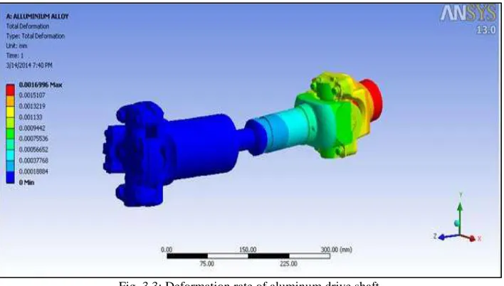
The fig. 3.3 shows the deformation rate of the drive shaft at the moment of 250 Nmm. With a maximum deformation of 0.0016996 mm and minimum deformation rate is 0mm.
Fig. 3.3: Deformation rate of aluminum drive shaft
The fig 3.4 gives the stress distribution of the drive shaft at 250 Nmm torque applied to it. It shows the maximum stress rate as 0.24563 Mpa and the minimum stress rate at 0 Mpa. But the stress occurred in the shaft is 0.1091 Mpa which shows it is safe to use.
Fig. 3.4: stress distribution of aluminum drive shaft
Carbon Fiber:
Fig. 3.5(a): Structural image of drive shaft
Fig. 3.5 (b): Meshing of drive shaft
Fig. 3.5 (c): Total deformation rate of carbon fiber drive shaft
Fig. 3.5(d): stress distribution of aluminum drive shaft
IV. RESULTS AND DISCUSSION
The table 5.1 shows the output of Comparison between aluminium and carbon fiber/epoxy and its feasibility. When compared to the aluminum drive shaft. The details were stated below in the table. We have tested both the aluminum and carbon fiber/epoxy drive at same value of torque at 250 Nmm.
MATERIAL ALUMINIUM CARBON FIBER/ EPOXY DEFORMATION IN mm 0.00169 0.000636
Graph 4.1 (a)
Graph 5.2 (b)
On comparing the result value of aluminum and carbon fiber/epoxy drive shaft, we prefer carbon fiber for usage.
V. CONCLUSION
The usage of composite materials has resulted in considerable amount of weight saving in the range of 81% to 72% when compared to conventional steel drive shaft. Taking into account the weight saving, deformation, stress induced and resultant frequency it is evident that carbon/epoxy composite has the most encouraging properties to act as replacement to aluminium. The present work was aimed at reducing the fuel consumption of the automobiles in particular or any machine, which employs drive shaft, in general. This was achieved by reducing the weight of the drive shaft with the use of composite materials.
By using advanced composite materials, the weight of the drive shaft assembly can be tremendously reduced. This also allows the use of a single drive shaft (instead of a two piece drive shaft) for transmission of power to the differential parts of the assembly. Apart from being lightweight, the use of composites also ensures less noise and vibration.
REFERENCE
[1] Parshuram.D, Sunil Mangsetty (2013) “DESIGN AND ANALYSIS OF COMPOSITE/HYBRID DRIVE SHAFT FOR AUTOMOTIVES” ISBN: 2319 –
1805, “The International Journal of Engineering and Science” Volume: 2, Issue: 1, pp. 160 – 171.
[2] Bhushan K. Suryawanshi, Prajitsen G.Damle (March 2013) “REVIEW OF DESIGN OF HYBRID ALUMINUM/ COMPOSITE DRIVE SHAFT FOR
AUTOMOBILE”- International Journal of Innovative Technology and Exploring Engineering (IJITEE), ISSN 2278 – 3075, Volume: 2, Issue: 4.
[3] M Arun, K.Somasundara Vinoth (May 2013) “DESIGN AND DEVELOPMENT OF LAMINATED ALUMINIUM GLASS FIBER DRIVE SHAFT FOR
LIGHT DUTY VEHICLES”- International Journal of Innovative Technology and Exploring Engineering (IJITEE), ISSN: 2278-3075 Volume: 2, Issue: 6.
[4] R.P.Kumar Romicharla, Dr. K. Rambabu (Sep-Oct 2012) “DESIGN AND OPTIMIZATION OF DRIVE SHAFT WITH COMPOSITE MATERIALS”-
International Journal of Modern Engineering Research (IJMER), ISSN 2249-6645 Volume: 2, Issue: 5, pp3422-3428.
[5] Harshal Bankar, Viraj Shinde, P. Baskar (Nov – Dec 2013) “MATERIAL OPTIMIZATION AND WEIGHT REDUCTION OF DRIVE SHAFT USING