1
Paper ID # 901267 PDF
A SYNC-LESS TIME-DIVIDED MAC PROTOCOL FOR MOBILE AD-HOC NETWORKS
Gentian Jakllari, Ram Ramanathan
BBN Technologies
Cambridge, MA
{gentian,ramanath}@bbn.com
ABSTRACT
Approaches to Medium Access Control (MAC) in mobile
ad hoc networks (MANETs) can be broadly classified into
TDMA and CSMA/CA. In principle, TDMA offers superior
performance as well as better capacity guarantees compared
to CSMA/CA. In practice, however, the need to provide
network-wide synchronization without centralized control,
and to accommodate mobility makes TDMA very hard to
design and implement. Consequently, CSMA/CA variants
are generally preferred. While the proliferation of real-time
multimedia applications demands a protocol with
TDMA-like features, the problem of doing so in a practically viable
manner remains unsolved.
We present SITA (Sync-less Impromptu Time-Divided
Ac-cess), a MAC protocol for real-time applications over
MANETs. SITA combines the advantages of TDMA with
the simplicity and robustness of CSMA/CA. SITA provides
on (traffic) demand, reserved access to the channel and
automatic admission control, while it does not require slot
synchronization. The main idea behind SITA is to set up
an impromptu, loose, conflict free schedule relative to an
initial control exchange. We study the performance of SITA
when implemented as an overlay over 802.11 in the ns-2
simulator. Our results show that, with real-time like traffic,
SITA provides significant improvement in the end-to-end
throughput, by as much as 300%, and on order of magnitude
or more decrease in the end-to-end delay and jitter when
compared with the vanilla 802.11.
I. I
NTRODUCTIONMedium Access Control (MAC) is a critical component of
any mobile ad hoc network (MANET). The MAC sub-layer
converts raw physical capacity into usable network capacity,
and thus the choice of a MAC protocol significantly impacts
MANET performance. In today’s MANETs this choice is
overwhelmingly in favor of
contention-based
protocols, in
particular, the IEEE 802.11 DCF [2]. This is partly due to
THIS PROJECT WAS SUPPORTED UNDER AFRL CONTRACT FA8750-06-C-0077.
the cheap availability of IEEE 802.11 cards, and partly due
to the fact that its simplicity, robustness and flexibility are a
ready fit for MANETs.
The unfolding future, however, presents a challenge:
real-time mulreal-timedia applications are increasing their dominance
in the Internet, and spilling over into MANETs and Mesh
Networks. To support this, the MAC architecture needs to be
fundamentally reservation-oriented, that is, provide capacity
guarantees and admission control. Unfortunately, the 802.11
DCF is not such a protocol, and while the community has
invented several ingenious variations [1], [17] to make it
real-time friendly, it is clear that these are not long term solutions.
In contrast,
contention-free
access as exemplified by Time
Division Multiple Access (TDMA) is widely acknowledged
as being an excellent fit for providing requisite QoS for
real-time applications, as it enables allocation of dedicated
chan-nel capacity to flows. However, broadly speaking, TDMA
needs two things that 802.11 doesn’t:
synchronization
of
frames and slots, and
allocation
of slots to nodes/links. In
MANETs, unlike in cellular networks, the lack of centralized
control and mobility of nodes makes both of these extremely
hard. Even when solved, the need for guard times between
slots and control messages for allocation both lead to low
efficiency that negates the advantages provided by TDMA
over 802.11. Furthermore, synchronization is inherently not
scalable with network size. Despite numerous efforts [15],
[10], [12], the problem of providing practically viable
so-lutions to these two challenges has not been satisfactorily
solved, resulting in the community being stuck in sub-optimal
solutions.
In this paper, we present SITA – Sync-less, Impromptu,
TdmA, a MAC protocol for MANETs that combines the
real-time friendliness of TDMA with the simplicity and robustness
of 802.11. Instead of trying to
solve
the MANET
synchro-nization and distributed dynamic allocation problem, SITA
simply
bypasses
them by using short-lived, impromptu and
is successful the node transmits data packets contention-free
periodically on the reserved allocation for as long as there are
ready packets. The transmitter, the receiver and the interfering
nodes keep track of the reservation using their local clocks
only - no clock synchronization across the nodes is necessary.
In summary, SITA has the following features:
1) SITA does not require clock synchronization, or
network-wide slot synchronization.
2) It provides on (traffic) demand reserved channel access.
3) The signaling control overhead is even less than that
of 802.11 (amortized over all packets).
4) It is conceptually simple and easy to implement.
5) It can be implemented as a stand-alone MAC or as a
software overlay on top of the widely deployed 802.11
MAC.
The last point is significant in practical terms and
penetra-tion potential. Unlike many proposals that need changing the
802.11 card firmware, overlaying SITA over 802.11 allows
compatibility with existing 802.11 networks and incremental
deployment.
We describe and analyze the performance of SITA using
ns-2 simulations. We have implemented a high fidelity model
of SITA as an overlay over the ns-2 802.11 DCF
implemen-tation. Our simulations show that the throughput of real-time
like traffic with overlay-SITA is improved by as much as
300%, while the end- to-end delay and jitter are decreased
by an order of magnitude or more when compared with
vanilla 802.11. Furthermore, we show that SITA continues
to perform well with bursty traffic and in the presence of
mobility.
The rest of the paper is organized as follows. In Section
II we describe SITA. In Section III we show how SITA can
be implemented as overlay on a off-the-shelf 802.11 card. In
Section IV we present simulations results. Finally, in Section
V we describe the previous work.
II. SITA D
ESIGNSITA is designed to provide TDMA-like capacity
guaran-tees without requiring global synchronization. Furthermore,
the capacity allocation is based on traffic demands and it is
negotiated using random access. This makes SITA friendly
to bursty traffic and more robust to mobility than traditional
TDMA.
SITA works as follows. A request for capacity from the
higher layers is converted into a time-periodic, fractional
share of the channel capacity. To reserve the specific share,
SITA negotiates with its neighbors using random access.
If the reservation is successful, it will be used for data
transmission for as long as there are ready packets. The
transmitter, the receiver and the interfering nodes will keep
track of the reservation using their local clock, which need
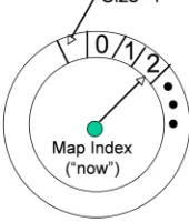
Fig. 1. The reservation map.
not be synchronized with each other, and by exploiting the
time periodicity of the share.
All the SITA functionality is based on a novel concept
we refer to as the
Reservation Map
. We start the description
of SITA by first presenting the Reservation Map. Following
that, the SITA procedures for capacity reservation, data
transmission and recovery are presented.
A. The Reservation Map
The Reservation Map (RM or simply “map”) is a novel
concept that provides a simple layer of abstraction between
the physical channel and SITA and provides the following
capabilities:
a. The reservation map allows describing an arbitrary
ca-pacity request as a time share of the channel. This description
is succinct and universal across the network.
b. It greatly simplifies admission control. The available
ca-pacity at any point in time, which is necessary for performing
admission control but at the same time notoriously difficult to
estimate in MANETs, is readily provided by the reservation
map.
c. Unlike the traditional TDMA frames, it has no
synchro-nized frame boundaries.
The RM is best visualized as a circular strip (see Fig.1)
with circumference representing time, and capacity shares
represented by “slices” of the strip. All nodes have the same
RM length (circumference and hence radius). The
Reserva-tion Map is divided in time units, equal in length for all the
nodes. The total number of units on the Reservation Map
represents the total capacity of the channel. A transmission
that requires half the capacity of the channel would occupy
half its units. A
Map Index
is used to “tell” the current unit
at any point in time. The Map Index “moves” clockwise
(without loss of generality) by making use of the local clock.
A RM “tick” occurs when the difference between the current
time, as indicated by the local clock, and the time of the last
“tick” is equal to the unit size.
The map in every node has three regions:
allocated period
(AP), indicating shares that are allocated for this node’s
transmission;
occupied period
(OP) indicating shares that are
BBN Proprietary
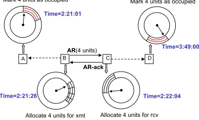
Channel Reservation
Channel Reservation
A B C D
AR(4 units)
AR-ack
Allocate 4 units for xmt Allocate 4 units for rcv
Time=2:21:26 Time=2:22:04
Mark 4 units as occupied Mark 4 units as occupied
Time=2:21:01
Time=3:49:00
Fig. 2. Clocks at each node may be unsynchronized. Nodes set up impromptu reservations relative to AR and AR-ack
period
(FP), which is not allocated or occupied and can be
used for new transmissions.
The RM is utilized by the reservation procedure, described
below, to perform TDMA like channel reservation without the
need for time synchronization. In particular, the reservation
procedure updates the AP/OP/FP state of the map units in
response to capacity requests.
B. Reservation Procedure
The channel reservation procedure takes as input a request
for capacity in bits/sec for a specific flow
1. Depending on the
available channel capacity, it either reserves enough floor to
satisfy the flow request or it turns it down and the flow is
denied admission.
The procedure is executed in two steps. First, the capacity
request is converted into a share of the reservation map. After
that, if possible, the share is reserved by the random access
based negotiation procedure.
1) Capacity to map share conversion:
The conversion is
a function of the capacity demand, reservation map size and
the link
2capacity. If D is the capacity demand, map size, the
RM size, and C, the link capacity, then,
req units
=
d
D
C
×
map size
e
where
req units
is the share size in terms of RM units.
2) Negotiation procedure:
The negotiation procedure has
two objectives: (1) to ensure allocation of time shares at
the receiver, if available; and (2), to get interfering nodes
to update their RM to reflect this allocation as an Occupied
Period.
The procedure is identical to the RTS/CTS exchange
employed by IEEE 802.11 for reserving channel capacity. We
desribe the steps followed by all the nodes involved during a
channel reservation negotiation with a specific example (see
Fig. 2). Note that we deliberately assume that the clocks of
1
Best effort packets are treated as belonging to a single flow called “best effort”.
2
The same node may realize different capacities with different neighbors.
the four nodes are not synchronized with each other and thus
their respective map indexes “tell” different units.
Source Procedure:
Let us assume that node B needs to
allocate 4 units for a flow that crosses the link
B
→
C.
Node B first looks for a FP share of size 4 on its RM.
If such a share is not found the process is terminated and
the flow is denied admission. Otherwise, B sends an Access
Request (AR) packet to the C indicating a request for channel
access. The AR packet consists of three fields: the source (B)
and destination (C) addresses and the
req units
(4)
. B then
waits for an AR-ACK from C. If it receives an AR-ACK, the
share of its RM starting at the unit the map index currently
“tells”, say
x
B, up to
x
B+ 4
is marked as allocated for
the particular flow. The data exchange component (described
later in this section) will be invoked to transmit data packets
contention free every time the map index “tells” between
x
Band
x
B+ 4
. If B does not receive an AR-ACK within a
certain amount of time, it will assume the AR failed and the
above process will be repeated after a randomly selected time
period. If the process fails for a pre-defined number of times,
it is terminated and the particular flow is denied admission.
Destination Procedure:
Upon receiving an AR packet, the
destination (node C) node will check its Reservation Map,
starting at the unit the map index tells at the moment, say,
x
C. Note that
x
Ccan be, and in our example is, different
from
x
B. If, starting from
x
C, there are 4 FP units available,
C will update its reservation map by setting the units from
x
Cup to
x
C+ 4
as Allocated Period (OP) and will reply
with a AR-ACK. The AR-ACK contains the same field as
AR. Node C will be expecting data from node B every time
C’s map index is between
x
Cand
x
C+ 4
.
If C does not possess the amount of free units required,
the AR is silently discarded.
The rest of the network:
Every node, in our example nodes
A and D, that receives an AR or AR-ACK packets which is
not destined at them reads the field containing the
req units
and updates their respective RMs. Starting at the unit their
map indexes tell, the next
req units
will be set to Occupied
Period (OP) status.
3) Reservation tracking procedure:
When a node allocates
or occupies a chunk of the RM it initiates a reservation
tracking procedure for this chunk. The sole purpose of this
procedure is to check whether any transmission takes place
during the respective chunk. If no transmission takes place
for a predefined number of cycles, the status of the chunk
will be set to Free Period (FP). New flows may now allocate
this chunk.
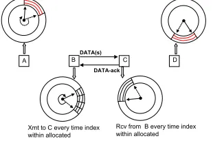
C. Data Transmission Procedure
BBN Proprietary Data Exchange Data Exchange
A BDATA(s) C D
DATA-ack
Xmt to C every time index within allocated
Defer every time index within occupied Defer every time index within occupied
Rcv from B every time index within allocated
Fig. 3. Node B will transmit data to node C every time its map index “tells” the previously reserved share. Nodes C, A, and D know when B will transmit by virtue of their reservation maps.
(see Fig. 3), node B will transmit data to node C every time
its map index is in the space allocated for the flow
B
→
C.
Nodes C, D, and A will be aware of B’s transmissions by
simply checking their respective RMs. It is important to point
out that during the data transmission procedure only the first
and the last unit of the reserved share are relevant. Node B
will send data to C as fast as it can until the map index “tells”
the last unit of the reserved share.
Although the data transmission is contention-free, SITA
employs ARQ to cope with channel errors and with those
few cases when the allocation may fail. A SITA transmitter
will send a burst of several packets at a time (the burst size is
a parameter) and will require only a single ACK in response.
If the ACK is not received within a certain time interval, all
the packets will be retransmitted. On the receiving side, the
SITA node will reply with an ACK if and only if all the data
packets of the burst are received.
D. Allocation Failures and SITA Recovery Procedure
The above establishes a pseudo-TDMA regime with each
node transmitting at pre-announced times for durations based
entirely on its local clock. The initial access rules make it
so that in the ideal case the transmissions from different
nodes are collision free. However, in reality, a number of
things disturb this condition. For example, mobility of nodes
may bring a node, whose reservation map does not include
current conditions, into conflict; transmissions may get out
of sync due to clock drift (we explore the effect of clock
drifts in more detail in the next subsection); packets may be
lengthened due to the radio dropping its rate down (say from
11 Mbps to 5.5 Mpbs to 2 Mbps etc). For these reasons, SITA
includes a recovery and re-sync scheme which is based on
re-doing the access.
A recovery/re-sync is initiated whenever there is no ACK
in response to a DATA for more than a certain number
of attempts. Each node in this situation triggers a fresh
access procedure (see above) in the existing FPs (that is, they
exclude the time share on which the unsuccessful DATA was
sent).
E. Addressing Clock Drifts
In order for SITA to work as described above, all of the
nodes that have marked a specific reservation on their RM
need to count units at the same speed. This in turn implicitly
assumes that clocks on nodes run at the same speed. In
practice, however, this is seldom true due to manufacturing
variations. Clocks typically run at marginally different speeds
resulting in
clock drift
. Clock drift may eventually result
in the transmitter and receiver disagreeing on when the
reservation starts within their RMs.
To deal with the clock drifts SITA uses guard bands. One
RM unit at the beginning and one at the end of every share
reservation are left unutilized. For example, if the request
for capacity is 4 units, SITA will actually reserve 6 but it
does not transmit any packets on the 1st and 6th unit. In the
following we show that for practical settings and clock drifts
the SITA guard bands are very effective.
If we denote the clock drift with
C
drif t, then, a reservation
will spill into either of the guard bands, on every repetition,
by:
RM
size×
C
drif twhere
C
drif tis measured in PPM (parts per million).
Thus, the number of repetitions the guard band will protect
the reservation for is:
b
unit size
RM
size×
C
drif tc
After this number of repetitions is exceeded reservations
may start to overlap and are not guaranteed anymore to
be contention free. If this happens and it results in packet
collisions
3, the SITA recovery procedure described in the
previous subsection will kick in.
Let us consider some realistic value for the variables above
to get a better sense of the effectiveness of the SITA guard
bands. In our simulations we have used
RM
size= 100
msec
and
unit size
= 2
msec. In [14] it is reported that for the
Telos mote platform the clock drift is 21 PPM. For these
values, a RM reservation will spill
2
.
1
µsec
into the guard
band on every repetition. Thus, the guard band will protect
the reservation from the clock drift for 952 repetitions or 95
seconds. In our simulations, even with a reservation that was
one tenth of the RM, SITA was able to transfer 4 data packets
of 500 bytes on every repetition. That translates to 3808 data
packets of 500 bytes before the recovery procedure may have
to kick in and the reservation be done anew. Alternatively,
SITA could be modified so that it proactively reserves a
new share and abandons the current when it realizes that
the current share is about to spill outside the guard band. We
leave this for future work.
3Collisions will only happen if there are two reservation separated only
III. SITA A
SO
VERLAYSITA can be implemented as a stand alone MAC protocol
or as a software overlay (sublayer) on top of the widely
deployed 802.11 MAC. In the following we show how SITA
can be implemented on top of a off-the-shelf 802.11 card
without making any modification to its firmware. With our
approach, the 802.11 code will remain untouched. A new
“sublayer” (overlay) is written on top that uses 802.11 MAC
as a data pipe, and all time management and access arbitration
is performed within the overlay. To 802.11, the SITA packets
are merely higher layer data packets.
Recall from Section II that SITA has four packet types:
AR, AR-ACK, DATA and DATA-ACK. The AR packet is to
be sent using random access, while the rest of the packets
are to be sent contention free. Below we show how each of
these SITA packets can be sent the way they should through
an 802.11 card.
a) Transmitting AR:
To comply with the SITA
seman-tics, the behavior of the 802.11 cards needs be modified to
transmit the AR only once, and without the automatic ACK.
Both requirements are achieved by forwarding the AR to the
802.11 as a “broadcast” packet type.
b) Transmitting AR-ack, DATA, DATA-ack:
SITA
re-quires transmitting these packets contention free. Thus, it is
necessary that AR-ack, DATA and DATA-ack cut through
the 802.11 and reach the physical layer with no delay. To
achieve this, all the packets are forwarded to the 802.11 card
as “broadcast” packet types while the carrier sensing and the
backoff are disabled [5], [7].
In Section IV, we use the approach describe above to
implement SITA as on overlay on top of the 802.11 ns-2
implementation.
IV. S
IMULATIONSIn this section we present the performance evaluation of
SITA. We have implemented SITA in the ns-2 simulator as
an overlay over the IEEE 802.11 implementation, following
the approach described in Section III. The exact policy for
admission control is beyond SITA’s scope. However, for
the purpose of these simulations we follow a simple first
come first serve approach. We make the following main
observations in our experiments:
•
With real-time like loads, SITA improves the
end-to-end throughput by as much as 300%, and decreases the
end-to-end delay and jitter by on order of magnitude or
more, when compared with the vanilla 802.11.
•
SITA continues to perform better than 802.11 in terms
of throughput, end-to-end delay and jitter even in the
presence of high node mobility and with bursty traffic,
albeit by not the same margins.
A. Simulations Settings
In all the experiments, unless otherwise specified, the
packet size is set to 500 bytes, the transmission rate to 11
Mbps and the simulation time to 150 seconds. The RM size
is set to 100 msec. This bounds the per hop delay by 100
msec, which is deemed acceptable for voice latency [18].
The RM
unit size
needs to be as small as possible to allow
SITA good granularity in assigning RM shares. However, it
has to big enough to allow for a packet transmission. For
out settings this size is 2 msec. For most experiments, we
use CBR traffic over UDP, which is similar to the traffic a
real-time multimedia application is expected to generate. We
also run experiments with bursty traffic and mobile nodes for
which reservation based MAC protocols traditionally perform
poorly. The metrics of interest are end-to-end throughput,
delay and jitter
B. Experiment 1: Grid topology
We first analyze the behavior of SITA over long flows that
are subject to high interference. For this purpose we use a
64 node Manhattan grid. Eight source destination pairs are
selected such that the source is on one side of the grid and
the destination on the other side. Every source generates CBR
traffic at varying loads.
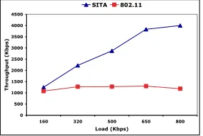
Results and Discussion:
The throughput for each flow is
depicted in Fig. 4, while the overall network throughput in
Fig. 5. As we can see in Fig. 4, at high loads, IEEE 802.11
becomes extremely unfair, resulting in high variance in the
realized throughput among the flows. SITA, on the other
hand, thanks to its capacity allocation mechanism is able to
always deliver the promised capacity to as many flows as
possible, while denying capacity to those flows that simply
cannot be accommodated. SITA’s approach leads to fairness
among those flows that were admitted, as shown in Fig. 4(a),
as well as in much higher overall network throughput, by as
much as 300%, as shown in Fig. 5. The same behavior is
also observed when analyzing the end-to-end delay. SITA’s
allocation mechanism allows for expedited (contention free)
delivery of the packets, as shown in Fig. 6(a), over the
pre-reserved capacity. The pre-pre-reserved capacity leads also to
very low jitter values, as shown in Fig. 6(c). With IEEE
802.11, at high loads, the unfair sharing of the capacity and
the contention leads to certain flows suffering an order of
magnitude or more higher end-to-end delay and jitter (Fig.
6(b) and Fig. 6(d)) when compared with SITA.
C. Experiment 2: Performance with Mobile Nodes
0 500 1000 1500 2000 2500 3000 3500
160 320 500 650 800
Load (Kbps)
Throughput (Kbps)
SITA 802.11
(a) Overall throughput .
0 10 20 30 40 50 60 70 80 90
160 320 500 650 800
Load (Kbps)
End-to-End Delay (msec)
SITA 802.11
(b) Average End-to-End Delay.
0 20 40 60 80 100 120 140 160
160 320 500 650 800
Load (Kbps)
End-to-End Jitter (msec)
SITA 802.11
(c) Average Jitter.
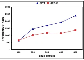
Fig. 7. Experiment 2: 50 nodes on a 3 by 3 unit, flat topology; all the nodes move following the random waypoint model. 10 CBR flows are established over 10 source destination pairs selected at random. SITA continues to performs well when compared with 802.11, despite the high node mobility. In terms of throughput, SITA performs just as good or slightly better than 802.11, while dramatically improving the end-to-end delay and jitter at high loads.
SITA -- CBR Traffic
0 100 200 300 400 500 600 700 800 900
160 320 500 650 800
Load (Kbps)
Throughput (Kbps)
(a) SITA Throughput.
802.11 -- CBR Traffic
0 100 200 300 400 500 600 700 800 900
160 320 500 650 800
Load (Kbps)
Throughput (Kbps)
(b) IEEE 802.11 Throughput.
Fig. 4. Experiment 1: 8 by 8 Manhathan grid; 8 flows generating CBR traffic. At high loads, IEEE 802.11 becomes extremely unfair, resulting in high variance in realized throughputs among flows. SITA, on the other hand, delivers fair throughput to as many flows as possible.
0 500 1000 1500 2000 2500 3000 3500 4000 4500
160 320 500 650 800
Load (Kbps)
Throughput (Kbps)
SITA 802.11
Fig. 5. Experiment 1: 8 by 8 Manhathan grid; 8 flows generating CBR traffic. SITA offers several times increase in the overall network throughput for moderate to high loads.
large number of flows and the nodes are mobile. 50 nodes are
placed uniformly at random on a 3 by 3 units flat topology.
We select at random 10 source destination pairs and generate
data flows at constant bit rate (CBR). All the nodes in the
network are mobile. We use the random waypoint model.
The maximum speed in the simulations is 10 m/s, while the
minimum is 0 m/s.
Results and Discussion:
The results for the overall network
throughput and the average end-to-end delay and jitter are
depicted in Fig. 7. At low load the performance of SITA
and IEEE 802.11 is similar. However, as the load increases,
SITA is able to deliver approximately 25% more throughput,
while incurring a much lower end-to-end delay. Two are the
reasons that the improvement in throughput achieved by SITA
SITA -- CBR Traffic (Logarithmic Scale for Y-Axis)
1 10 100 1000 10000
160 320 500 650 800
Load (Kbps)
Delay (msec)
(a) SITA End-to-End Delay.
802.11 -- CBR Traffic (Logarithmic Scale for Y-Axis)
1 10 100 1000 10000
160 320 500 650 800
Load (Kbps)
Delay (msec)
e
(b) 802.11 End-to-End Delay.
SITA -- CBR Traffic (Logarithmic Scale for Y-Axis)
0.1 1 10 100 1000 10000
160 320 500 650 800
Load (Kbps)
Jitter (msec)
(c) SITA End-to-End Jitter.
802.11 -- CBR Traffic (Logarithmic Scale for Y-Axis)
1 10 100 1000 10000
160 320 500 650 800 Load (Kbps)
Jitter (msec)
(d) 802.11 End-to-End Jitter.
Fig. 6. Experiment 1: 8 by 8 Manhathan grid; 8 flows generating CBR traffic. At high loads, IEEE 802.11 becomes extremely unfair, resulting in many flows experiencing very high end-to-end delay and jitter. SITA delivers the data on all the flows at very low end-to-end delay and jitter.
is lower than what was observed in experiment 1. First, the
paths here are shorter and, as also observed in the experiment
2, 802.11 performs well over 1 and 2 hop paths. Second, the
high node mobility makes the life of any reservation shorter,
forcing SITA to invoke the recovery and leading to higher
overhead per data packet delivered.
D. Experiment 3: Performance with Bursty Traffic
0 500 1000 1500 2000 2500 3000
160 320 500 650 800
Load (Kbps)
Throughput (Kbps)
SITA 802.11
Fig. 8. Experiment 3: 8 by 8 Manhathan grid; 8 flows generating bursty traffic. SITA offers significant increase in the overall network throughput, by as much as 100%, for moderate to high loads, when compared with 802.11.
only the overall network throughput in Fig.8. As the data
shows, SITA continues to significantly outperform 802.11,
by as much as 100%, albeit not by the margin observed for
the CBR traffic.
V. R
ELATEDW
ORKThere is a large body of work on MAC protocols for
MANETs and a complete account is beyond the scope
of this paper. Instead, in this section, we describe some
representative work.
Random Access MAC Protocols:
IEEE 802.11 DCF
(based on CSMA/CA) has become the de-facto standard
reference for the research and development of MAC protocols
for MANETs. However, this protocol was designed and
engineered for WLANs. When used in MANETs, it presents
numerous shortcomings, such as unfairness [3] and spatial
bias [16]. Furthermore, the inherent weakness of CSMA/CA
in handling real-time traffic is exacerbated in the multihop
setting [9], [11].
TDMA MAC Protocols:
TDMA has been largely
dis-missed in the design of MAC protocol for MANETs mainly
due to its demand for tight network wide synchronization and
its poor channel utilization under bursty traffic. There are a
few exceptions, however, of TDMA MAC especially in the
military context [18], and emerging networks [8], [6] where
CSMA is not an option.
Protocols Based (in part) on CSMA:
These protocols can
be broadly classified in two categories: protocols that provide
service differentiation, and CSMA/TDMA hybrids.
Service differentiation.
In the first category [1], the
modi-fication still maintains the CSMA nature of the protocol but
make changes to the backoff procedures so that the
prob-ability of accessing the channel depends on some assigned
priority. However, in the presence of multiple flows with the
same priority the protocol with fall back to pure CSMA.
CSMA/TDMA hybrids
: In [4], [13] it is proposed to use
CSMA for accessing the channel and then holding it, in
TDMA fashion, for as long as it is necessary. Thus, no
synchronization is required and the channel allocation is
based on traffic demand, while at the same time there are
capacity share guarantees. However, both works assume that
the real-time traffic packets arrive at a specific and universal
rate. This would not hold in scenarios where different kinds of
real-time traffic, e.g video, VOIP, are present simultaneously
in the network. Finally, both protocol have no efficient way
of dealing with node mobility.
R
EFERENCES[1] Wireless LAN Medium Access Control (MAC) and Physical Layer (PHY) Specifications, Amendment 8: Medium Access control (MAC) Quality of Service Enhancements, IEEE Std. 802.11e-2005 (Novem-ber 2005).
[2] Wireless LAN Medium Access Control (MAC) and Physical Layer (PHY) Specifications, IEEE Std. 802.11, January 1997.
[3] Violeta Gambiroza, Bahareh Sadeghi, and Edward W. Knightly. End-to-end performance and fairness in multihop wireless backhaul networks. InACM MobiCom ’04.
[4] C. R. Lin and M. Gerla. Asynchronous Multimedia Multihop Wireless Networks. InIEEE INFOCOM ’97.
[5] M. Neufeld, J. Fifield, C. Doerr, A. Sheth, and D. Grunwald. SoftMAC-flexible wireless research platform. InHotNets-IV. [6] Jim Partan, Jim Kurose, and Brian Neil Levine. A survey of practical
issues in underwater networks. InWUWNet ’06: Proceedings of the
1st ACM international workshop on Underwater networks.
[7] R. Patra, S. Nedevschi, S. Surana, A. Sheth, L. Subramanian, and E. Brewer. WiLDNet: Design and Implementation of High Perfor-mance WiFi Based Long Distance Networks.NSDI, 2007.
[8] Bhaskaran Raman and Kameswari Chebrolu. Design and evaluation of a new MAC protocol for long-distance 802.11 mesh networks. In
ACM MobiCom ’05.
[9] Ram Ramanathan. Challenges: a radically new architecture for next generation mobile ad hoc networks. InACM MobiCom ’05.
[10] S. Ramanathan. A Unified Framework and Algorithm for (T/F/C)DMA Channel Assignment in Wireless Networks. In
INFO-COM ’97, page 900, Washington, DC, USA. IEEE Computer Society.
[11] Ananth Rao and Ion Stoica. An overlay MAC layer for 802.11 networks. InACM MobiSys ’05.
[12] Injong Rhee, Ajit Warrier, and Lisong Xu. Randomized Dining Philosophers to TDMA Scheduling in Wireless Sensor Networks. Technical report, Department of Computer Science, North Carolina State University, April 2005.
[13] Sumit Singh, Prashanth Aravinda Kumar Acharya, Upamanyu Mad-how, and Elizabeth M. Belding-Royer. Sticky CSMA/CA: Implicit synchronization and real-time QoS in mesh networks.Ad Hoc Netw., 5(6):744–768, 2007.
[14] Hoi-Sheung Wilson So, Giang Nguyen, and Jean Walrand. Practical synchronization techniques for multi-channel MAC. InACM
Mobi-Com ’06.
[15] Bharath Sundararaman, Ugo Buy, and Ajay D. Kshemkalyani. Clock synchronization for wireless sensor networks: a survey. Ad Hoc
Networks, 3(3):281–323, 2005.
[16] Karthikeyan Sundaresan, Hung-Yun Hsieh, and Raghupathy Sivaku-mar. IEEE 802.11 over multi-hop wireless networks: problems and new perspectives. Ad Hoc Netw., 5(6):744–768, 2003.
[17] Nitin H. Vaidya, Paramvir Bahl, and Seema Gupta. Distributed fair scheduling in a wireless LAN. InACM MobiCom ’00.
[18] C.D. Young. USAP multiple access: dynamic resource allocation for mobile multihop multichannel wireless networking. IEEE MILCOM