INTRODUCTION
Nowadays, reverse engineering is encoun-tered in various branches of engineering. This is a specific approach that enables to effectively link the measurement technique, laser or CT scan-ners, with a computer environment. This type of connection allows transforming the scanned data into the digital form and processing them with the computer. The way these data are processed is part of reverse engineering. Reverse engineering is known as the process of duplicating an exist-ing component sub-assembly or product without using a drawing documentation or a computer model [2, 3, 16]. Reverse engineering has a wide use. It is mainly employed in the cases where the product documentation is missing or has never existed.
The laser scanning has a wide application in the field of the engineering industry. A laser stripe is projected onto a surface and the reflected beam is detected by CCD cameras. Three-dimensional coordinates are acquired through the image pro-cessing and triangulation method [4].
The cloud of points originates because of laser scanning. The external surface of an object is rep-resented with a set of discrete points. Individual
points are described in the file with their 3D co-ordinates. The density of the points on the surface is optional at certain intervals; for example, in the engineering industry it is roughly 1 to 0.2 mm be-tween two points.
Triangulation is a method which uses loca-tion and angles between light sources and photo sensing devices to deduce position. A high energy light source is focused and projected at a pre-specified angle at the surface of interest [1, 18]. It forms the basis for the algorithms that are ap-plied to the cloud of points. After scanning the object with a laser scanner, it is necessary to process the obtained cloud of points. It is carried out by trigonometric calculation. The solution is to connect individual points together to a mesh that describes the geometry of the scanned object. Nowadays, there are several meshing algorithms that enable us to solve this type of problem.
POISSON SURFACE RECONSTRUCTION
In his paper, Michael Kazhdan “We show that surface reconstruction from oriented points can be cast as a spatial Poisson problem. This Pois-son formulation considers all the points at once,
Realization and Verification of Data Conversion
from Laser Scanner to FEM
Alžbeta Sapietová
1*, Ondrej Štalmach
1, Milan Sága
1, Dana Stančeková
1, Lukáš Gajdoš
21 University of Žilina, Faculty of Mechanical Engineering, Univerzitna 1, 010 26, Žilina, Slovak Republic
2 Schaffler Slovakia, Dr G Schaefflera 1, Kysucke Nove Mesto, Slovak Republic
* Corresponding author’s e-mail: [email protected]
ABSTRACT
This paper deals with the data processing in the form of a point cloud scanned using a handheld 3D laser scanner. The aim of the paper was to use this data to create a representative FEM model and compare two different ap
-proaches, one them involved creating a CAD model and the other one did not. The data processing was carried out in the freeware systems MeshLab and Meshmixer and FEM analysis in the software ANSYS Workbench.
Keywords: 3D laser scanner, data processing, CAD model, MeshLab, Ansys Workbench.
Volume 14, Issue 1, March 2020, pages 69–74
https://doi.org/10.12913/22998624/113285
Research Journal
Accepted: 2020.02.04without resorting to heuristic spatial partitioning or blending, and is therefore highly resilient to data noise. Unlike radial basis function schemes, our Poisson approach allows a hierarchy of lo-cally supported basis functions, and therefore the solution reduces to a well conditioned sparse linear system. We describe a spatially adaptive multiscale algorithm whose time and space com-plexities are proportional to the size of the recon-structed model” [5].
This contribution is based on this algorithm too because the goal is to obtain a watertight and smooth surface. Therefore, the MeshLab software is used because it has implemented the Poisson Surface Reconstruction mesh algorithm.
PROCESSING OF SCANNED
DATA AND MODELLING
After scanning an object into the cloud of points, a mesh is created from these points. As the reference object for this study a chrome-vanadium steel wrench, size 30 was used. It was scanned using the laser FARO Edge ScanArm HD in the company CEIT. A text file that contained the coordinates of cloud of points, defined in the cartesian coordi-nate system XYZ is received at the output from the scanner.
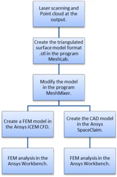
Figure 1 presents the whole workflow. After scanning the wrench using the laser scanner, the text file containing the positions of the points is import-ed to the freeware MeshLab software (see Fig. 2). A triangular surface model in the.stl format is cre-ated in this software (see Fig. 3). In MeshMixer, which is also freeware software, the information like the size of wrench and material from the sur-face of the model are removed by the smoothing tool (see Fig. 4 and Fig. 5). Afterwards, the two different approaches of further processing of the model are studied.
The first approach is a classic reverse en-gineering approach which includes the cre-ation of the volume CAD model, because the .stl model is only the triangular surface model. Volume CAD model is created in the Ansys SpaceClaim software. After importing the .stl model into the SpaceClaim, the main boundary curves of the future volume model are created with the use of intersection of 2D planes and tri-angular surface model.
Using these boundary curves, the volume model is created by re-modelling the triangular surface model. The volume model must be cre-ated as close as possible to the triangulcre-ated sur-face model. Then the volume model is used in the FEM analysis.
The second approach does not include the creation of volume CAD model. The .stl model is imported to the ICEM CFD module which is implemented in the Ansys Workbench and it is an effective tool for generating FEM meshes. This tool is used to create the surface mesh from the triangular surface model. Afterwards, this surface mesh is used to compute the volume mesh. Then, the volume mesh is used in the FEM analysis. [11–14].
FEM ANALYSIS
The FEM models from these two approaches are simulated in the Ansys Workbench software in the Static Structural module [9, 19]. The purpose of this paper was to compare the simulations of these two approaches; therefore, the simple and the same boundary conditions are set on the these
Fig. 4. Triangulated surface model with the characteristic information on the surface
Fig. 3. Triangulated surface model
both FEM models. In Figure 6, it is shown that the two parallel surfaces of the wrench are fixed and the pressure 0.59 MPa is applied on the other side of the wrench in the direction of the movement.
In the first approach, a computational mesh was created from the volume model before the simulation itself. The computational meshes con-tained about 350 000 elements in the both cases (see Fig. 7).
Both simulations were completed success-fully and the results are shown in Figure 8 and Figure 9.
The results are different. The maximum value of the von Mises stress in the 1st approach is placed
at the different locations than the maximum value of the von Mises stress in the 2nd approach and
the deviation of the results is 29.7%. The reason why the results are different may be the fact that
Fig. 9. Result of 2. Approach – Equivalent von Mises stress
Fig. 8. Result of 1. Approach – Equivalent von-Mises stress
Fig. 7. Computational mesh
the geometry of volume of the CAD model which is the first approach is a little different from the reference wrench because it is created by re-modelling from the triangulated surface model. Therefore, it cannot be 100% same as the original triangular surface model. A complete comparison of the approaches would require the comparison with an experiment at which deformations would be measured on a loaded object [10–17].
CONCLUSIONS
The two different approaches were compared; the first one included the creation of the volume CAD model and the other one did not. The results of the FEM analysis are different but the 2nd ap-proach may have better results because that geom-etry is almost an exact copy of the real reference wrench. The 1st approach has a little different ge-ometry in compare to the original. This problem is looked at from the viewpoint of the FEM analy-sis, rather than classic reverse engineering. [5–8]. Classic reverse engineering needs to create the volume CAD model because it is used for other applications, not only for the the FEM analysis.
In terms of the FEM analysis, the 2nd ap-proach is better because it does not require creat-ing the volume CAD model. When the volume CAD model is needed, the 2nd approach is use-less. However, in the situations where only the FEM analysis is needed, the 2nd approach is fast-er than the first one.
Acknowledgement
A The part of the results of this work has been supported by KEGA 017ŽU-4/2017 and 022ZU-4/2017 and VEGA 1/0073/19.
REFERENCES
1. Barta D., Mruzek M., Labuda, R., Skrucany T., Gardinsky L. Posslity of increasing vehicle energy balance using coasting, Advances in science and technology-research journal, 12, 2018, 228–235. 2. Barta D., Mruzek M., Factors influencing the hybrid
drive of urban public transport buses. Management systems in production engineering, 20(4), 2015, 213–218.
3. Bocko J., Lengvarsky P. Application of Finite Ele
-ment Method for Analysis of Nanostructures. Acta
(5) Bolitho M., Kazhdan M., Burns R. and Hoppe H. Parallel Poisson Surface Reconstruction. 5th In
-ternational Symposium on Visual Computing. Las Vegas, NV; United States 2009, 678–689.
4. Dekýš V., Kopas P., Sapieta M., Števka O. A de -tection of deformation mechanisms using infrared
thermography and acoustic emission. In: Applied Mechanics and Materials, 474, 2014, 315–320. 5. Halama R., Markopoulos A., Fojtik F., Fusek M.,
Poruba Z. and Famfulik J. Effect of stress amplitude on uniaxial ratcheting of aluminum alloy. Materi
-alwissenschaft und Werkstofftechnik, 48(8), 2017, 814–819.
6. Jakubovičová L., Sága M., Vaško M., Numerical study of influence of mutual slewing of roller bear
-ing r-ings on the principal stresses at contact area. Scientific journal of Silesian University of Technol
-ogy – Series Transport 84, 2014, 83–91.
7. Kopas P., Sága M., Baniari V., Vaško M., Handrik M., A plastic strain and stress analysis of bending and torsion fatigue specimens in the low-cycle fa
-tigue region using the finite element methods. Pro
-cedia Engineering, 177, 2017, 526–531.
8. Krawiec P., Domek G., Warguła Ł., Waluś K. and Adamiec J. The application of the optical system ATOS II for rapid prototyping methods of non-classical models of cogbelt pulleys. Sklene Teplice; Slovakia 2018, MATEC Web of Conferences, 157.
9. Kovacikova P., Bezdedova R., Vavro J., Jr., and Vavro J.Comparison of numerical analysis of stress-strain states of cast iron with vermicular graphite shape and globular graphite shape. VratnaTerchova; Slovakia, Procedia Engineering, 136, 2016, 28–32. 10. Kubiak M., Domanski T. and Dekys V., Measure
-ment of strain during tension test of welded joint using multi-camera 3D correlation system, Procedia Engineering, 177, 2017, 107–113.
11. Leitner B. and Vaško M., Design and Modelling of Tank Wagon Assembly Operations in CAM Envi
-ronment. In Kaunas and Klaipėda, Lithuania, Trans
-port Means 2015 I & II, 87–90.
12. Macko M., Flizikowski J., Szczepański Z., Tyszc
-zuk K., Śmigielski G., Mroziński A., Czerniak J. and Tomporowski A., CAD/CAE applications in mill’s
design and investigation. Lecture Notes in
Mechani-cal Engineering, 2017, 343–351.
13. Macko M., Tyszczuk K., Śmigielski G., Flizikowski J. and Mroziński A., The use of CAD applications in the design of shredders for polymers. Sklene Tep
-lice; Slovakia, MATEC, 157, 2018, 02027. 14. Novak P.and Zmindak M. Optimization of Cold
Pipelines Repaired by Steel Sleeve and Epoxy Com
-position. Litomerice, CZECH REPUBLIC, Applied Mechanics and Materials, 2013, 486, 181–188. 16. Stalmach O., Implementation and verification of
data conversion from the laser scanner to the FEM. Diploma thesis, Zilina: University of Zilina, 2017. 17. Son S., Park H. and Lee J. Automated laser scan -ning system for reverse engineering and
inspec-tion. International Journal of Machine Tools and
Manufacture, 42, 2002, 889–897.
18. Varady T., Martin RR. and Cox J. Reverse engineer
-ing of geometric models and introduction, Comput
-er Aided Design, 29, 1997, 255–268.