http: // www.ijrtsm.com© International Journal of Recent Technology Science & Management 38
ISSN : 2455-9679
[Chandrashekharet al. , 4(1), Jan 2019] Impact Factor : 2.865
IJRTSM
INTERNATIONAL JOURNAL OF RECENT TECHNOLOGY SCIENCE & MANAGEMENT
“
CFX ANALYSIS OF SHELL AND TUBE HEAT EXCHANGER USING BAFFLES WITH
DIFFERENT ANGLE OF INCLINATION
”
Chandra Shekhar Malviya
1,
Dr. S. K. Nagpure
21M.Tech Scholar, Dept. of Mechanical Engineering,
Scope College Of Engineering
Bhopal, MP, India2Associate Professor, Dept. of Mechanical Engineering,
Scope College Of Engineering
Bhopal, MP, India
ABSTRACT
In present day shell and tube heat exchanger is the most common type heat exchanger widely use in oil refinery and other large chemical process, because it suits high pressure application. Firstly modeling done on CATIA software and the process in solving simulation consists of modeling and meshing the basic geometry of shell and tube heat exchanger using CFX package ANSYS 17.0. The objective of the project is design of shell and tube heat exchanger with series of baffles and study the flow and temperature field inside the shell using ANSYS software tools. The process in solving simulation consists of modeling and meshing the basic geometry of shell and tube heat exchanger using CFD package ANSYS 17.0. The objective of the project is design of shell and tube heat exchanger with baffle and study the flow and temperature field inside the shell using ANSYS software tools. The heat exchanger contains 5 tubes and 600 mm length shell diameter 90 mm. The helix angle of baffle will be varied from 00, 300 to 450. In simulation will show how the pressure vary in shell due to different helix angle and flow rate. The flow pattern in the shell side of the heat exchanger with continuous baffles was forced to be rotational and Baffles Series due to the geometry of the continuous baffles, which results in a significant increase in heat transfer coefficient per unit pressure drop in the heat exchanger.
Keyword: Baffles, CFX, ANSYS, CATIA, Heat transfer, Flow
I.
I
NTRODUCTIONHeat exchanger is a device that continuously transfers heat from one medium to other medium in order to carry
process energy. The purpose of constructing a heat exchanger is to getan efficient method of heat transfer from one fluid to another, by direct contact or by indirect contact. Heat exchangers are one of the mostly used equipment in the process industries. Heat exchangers are used to transfer heat between two process streams. One can realize their usage that any process which involve cooling, heating, condensation, boiling or evaporation will require a heat exchanger for these purpose. Process fluids, usually are heated or cooled before the process or
undergo a phase change. Different heat exchangers are named according to their application. For example, heat exchangers being used to condense are known as condensers, similarly heat exchanger for boiling purposes are called
http: // www.ijrtsm.com© International Journal of Recent Technology Science & Management 39
ISSN : 2455-9679
[Chandrashekharet al. , 4(1), Jan 2019] Impact Factor : 2.865
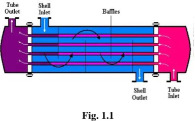
boilers. Shell and tube type heat exchanger consists of a number of tubes through which one fluid flows. Another fluid flows through the shell which encloses the tubes and other supporting items like baffles, tube header sheets, gaskets etc. The heat exchange between the two fluids takes through the wall of the tubes.
II.
M
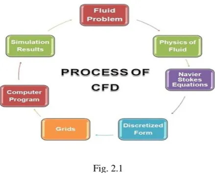
ETHODOLOGYCFD is a sophisticated computationally-based design and analysis technique. CFD software gives you the power to simulate flows of gases and liquids, heat and mass transfer, moving bodies, multiphase physics, chemical reaction, fluid-structure interaction and acoustics through computer modeling. This software can also build a virtual prototype of the system or device before can be apply to real-world physics and chemistry to the model, and the software will provide with images and data, which predict the performance of that design.
Fig. 2.1
CFD analysis of helical coil heat exchanger using Ansys 17.0, Cad model Generation of 3D model by using CATIA V 5R20 and exporting to the IGES. and then import in ANSYS fluent 17.0.
PRE PROCESSING
Create geometry and mesh for solving problem
CAD Model
Generation of 3D model by using CATIA ver 5.0
FVM Approach
By this method we can solve algebraic equation to get initial solution.
Set the transportation equation that needs to be solved. This can be solved by using
ANSYS Fluent 14.0 in Fluent setup
Set the fluid property
Set the boundary conditions
Set the Source term (Pressure)
SOLUTION:
Solution Method
Pressure Velocity coupling scheme
For 2D Problem we use Stream Function Vortices approach. For 3D Problem we use Primitive variable approach.
http: // www.ijrtsm.com© International Journal of Recent Technology Science & Management 40
ISSN : 2455-9679
[Chandrashekharet al. , 4(1), Jan 2019] Impact Factor : 2.865
Turbulence Modeling:-
K-ɛ turbulence model for turbulent flow equation Momentum second order Turbulence Kinetic energy second order (K)
Turbulence dissipation rate second order(ɛ)
SOLUTION INITIALIZATION:-
Initialized the solution to get the initial solution for the problem. By using SIMPLE solver ( Semi – implicit method for pressure linked equation).
RUN SOLUTION:-
Run the solution by giving 300 no of iteration for solution to converge.
POST PROCESSING:-
Post Processing:- For viewing and interpretation of Result, the result can be viewed in various formats like graph, value, animation etc.
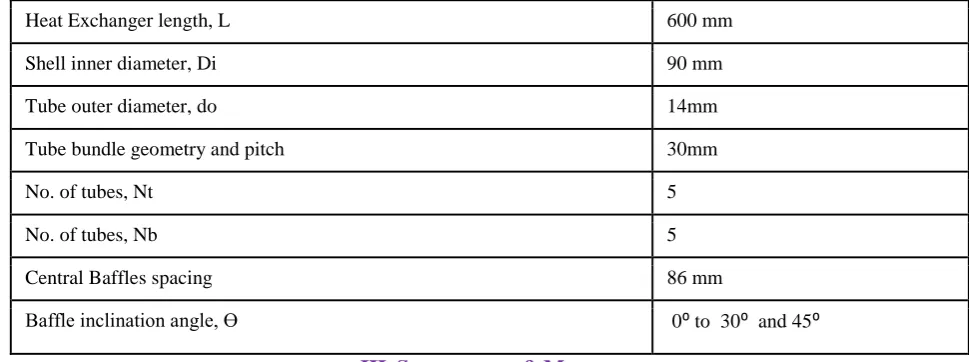
Table. 1 Geometric dimensions of shell and tube heat exchanger
III.
S
IMULATION&
M
ODELINGFig 3.1 Isometric view of arrangement of baffles and tubes of shell and tube heat exchanger with baffle inclination.
Heat Exchanger length, L 600 mm
Shell inner diameter, Di 90 mm
Tube outer diameter, do 14mm
Tube bundle geometry and pitch 30mm
No. of tubes, Nt 5
No. of tubes, Nb 5
Central Baffles spacing 86 mm
http: // www.ijrtsm.com© International Journal of Recent Technology Science & Management 41
ISSN : 2455-9679
[Chandrashekharet al. , 4(1), Jan 2019] Impact Factor : 2.865
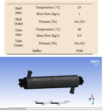
Table 3.1 Boundary Condition shell and tube heat exchanger
Fig 3.2 Meshing diagram of shell and tube heat exchanger
3.1 0° Degree Baffle Inclination Angle
http: // www.ijrtsm.com© International Journal of Recent Technology Science & Management 42
ISSN : 2455-9679
[Chandrashekharet al. , 4(1), Jan 2019] Impact Factor : 2.865
Fig.3.4 Heat exchanger 0° Inclination baffles Total temperature results
http: // www.ijrtsm.com© International Journal of Recent Technology Science & Management 43
ISSN : 2455-9679
[Chandrashekharet al. , 4(1), Jan 2019] Impact Factor : 2.865
Fig.3.6 Heat exchanger 0° Inclination baffles Turbulence kinectic energy results
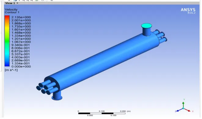
Fig.3.7 Heat exchanger 0° Inclination baffles velocity results
Fig. 3.8 Heat exchanger 0° Inclination baffles streamline velocity results
http: // www.ijrtsm.com© International Journal of Recent Technology Science & Management 44
ISSN : 2455-9679
[Chandrashekharet al. , 4(1), Jan 2019] Impact Factor : 2.865
Fig.3.9 Heat exchanger 30° Inclination baffles Total pressure results
Fig.3.10 Heat exchanger 30° Inclination baffles Total temperature results
Fig.3.11 Heat exchanger 30° Inclination baffles Turbulence kinectic energy results
http: // www.ijrtsm.com© International Journal of Recent Technology Science & Management 45
ISSN : 2455-9679
[Chandrashekharet al. , 4(1), Jan 2019] Impact Factor : 2.865
Fig.3.13 Heat exchanger 30° Inclination baffles streamline velocity results
3.3 45° degree Baffle Inclination Angle
Fig.3.14 Heat exchanger 45° Inclination baffles total pressure results
http: // www.ijrtsm.com© International Journal of Recent Technology Science & Management 46
ISSN : 2455-9679
[Chandrashekharet al. , 4(1), Jan 2019] Impact Factor : 2.865
Fig.3.16 Heat exchanger 45° Inclination baffles turbulence kintic energy results
Fig.3.17 Heat exchanger 45° Inclination baffles velocity results
http: // www.ijrtsm.com© International Journal of Recent Technology Science & Management 47
ISSN : 2455-9679
[Chandrashekharet al. , 4(1), Jan 2019] Impact Factor : 2.865
IV.
R
ESULT&
D
ISCUSSIONWe have take shall and tube types heat exchanger so we have consider here three case.
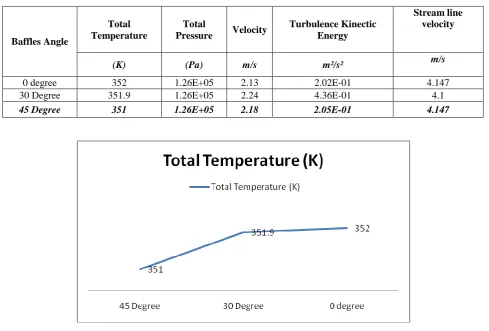
Case1: 0° degree inclination of baffles, here we find from CFX thermal solution help we find different thermal parameter like that total temperature, total pressure, turbulence kinetic energy, velocity and streamline velocity. So the value of total temperature, total pressure, turbulence kinetic energy, velocity and streamline velocity are respectively like that 352 K, 1.26E05, 2.13m/s , 2.02E-1 m2/s2and 4.147 m/s
Case2: 30°degree inclination of baffles, here we find from CFX thermal solution help we find different thermal parameter like that total temperature, total pressure, turbulence kinetic energy, velocity and streamline velocity. So the value of total temperature, total pressure, turbulence kinetic energy, velocity and streamline velocity are respectively like that 351.9 K, 1.26E05, 2.24m/s , 4.36 E-1 m2/s2 and 4.10 m/s
Case3: 45°degree inclination of baffles, here we find from CFX thermal solution help we find different thermal parameter like that total temperature, total pressure, turbulence kinetic energy, velocity and streamline velocity. So the value of total temperature, total pressure, turbulence kinetic energy, velocity and streamline velocity are respectively like that 351 K, 1.26E05, 2.18m/s , 2.05 E-1 m2/s2 and 4.147m/s
So we find all thermal parameter and here we have selected 45°degree inclination of baffles shell and tube types heat exchanger with replace exiting 0° degree inclination of baffles shell and tube type heat exchanger.
now here we have validate our result from "Sebastião José dos Santos Filho, Josedite Saraiva de Souza, Antonio Gilson Barbosa de Lima" . our result is very good compare to these author. so we can suggested this project work in future.
Baffles Angle
Total Temperature
Total
Pressure Velocity
Turbulence Kinectic Energy
Stream line velocity
(K) (Pa) m/s m²/s² m/s
0 degree 352 1.26E+05 2.13 2.02E-01 4.147
30 Degree 351.9 1.26E+05 2.24 4.36E-01 4.1
45 Degree 351 1.26E+05 2.18 2.05E-01 4.147
Fig.4.1 Total temperature comparison graph
http: // www.ijrtsm.com© International Journal of Recent Technology Science & Management 48
ISSN : 2455-9679
[Chandrashekharet al. , 4(1), Jan 2019] Impact Factor : 2.865
Fig.4.2 Turbulence kinectic energy comparison graph
Fig.4.3 Stream line velocity comparison graph
http: // www.ijrtsm.com© International Journal of Recent Technology Science & Management 49
ISSN : 2455-9679
[Chandrashekharet al. , 4(1), Jan 2019] Impact Factor : 2.865
V.
C
ONCLUSIONThis model can also be improved by using Nusselt number and Reynolds stress model, but with higher computational theory. Furthermore the enhance wall function are not use in this project, but they can be very useful. The heat transfer is poor because most of the fluid passes without the interaction with baffles. Thus the design can be modified for better heat transfer in two ways either the decreasing the shell diameter, so that it will be a proper contact with the baffle or by increasing the baffle so that baffles will be proper contact with the shell. It is because the heat transfer area is not utilized efficiently. So We can seen that when angle of inclination baffle will be increased then heat transferred we found that maximum. Here we use 0⁰, 30⁰ and 45⁰ degree inclination angle with baffles and 45⁰ degree inclination baffles we found minimum turbulence value compare to 0⁰ degree and 30⁰ degree inclination of baffles.
As reported in the development of this article, the design of a shell-and-tube heat exchanger is quite complex, requiring a good knowledge regarding its variables mainly regarding their velocity. However, our focus was related to flow rates and temperatures aiming this study for a later work.
The conclusions about this work were:
• Current lines, pressure and temperature fields behave as expected computationally • To find Turbulence kinetic energy.
• The baffles presence significantly increases the thermal exchange efficiency..
REFERENCES
1 A.O. Adelaja, S. J. Ojolo and M. G. Sobamowo, “Computer Aided Analysis of Thermal and Mechanical Design of Shell and Tube Heat Exchangers”, Advanced Materials Vol. 367 (2012) pp 731-737 © (2012) Trans Tech
Publications, Switzerland.
2 Yusuf Ali Kara, Ozbilen Guraras, “A computer program for designing of Shell and tube heat exchanger”, Applied Thermal Engineering 24(2004) 1797–1805.
3 Rajagapal THUNDIL KARUPPA RAJ and Srikanth GANNE, “Shell side numerical analysis of a shell and tube heat exchanger considering the effects of baffle inclination angle on fluid flow”, Thundil Karuppa Raj, R., et al.: Shell Side Numerical Analysis of a Shell and Tube Heat Exchanger ,THERMAL SCIENCE: Year 2012, Vol. 16, No. 4, pp. 1165-1174.
4 S. Noie Baghban, M. Moghiman and E. Salehi, “ Thermal analysis of shell-side flow of shell-and tube heat exchanger using experimental and theoretical methods” (Received: October 1, 1998 - Accepted in Revised Form: June 3, 1999).
5 A.GopiChand, Prof.A.V.N.L.Sharma , G.Vijay Kumar, A.Srividya, “ Thermal analysis of shell and tube heat exchanger using mat lab and floefd software”, Volume: 1 Issue: 3 276 – 281, ISSN: 2319 – 1163.
6 Hari Haran, Ravindra Reddy and Sreehari, “Thermal Analysis of Shell and Tube Heat Exchanger Using C and Ansys” , International Journal of Computer Trends and Technology (IJCTT) – volume 4 Issue 7–July 2013. 7 J. Li and G.P. Peterson, “Experimental measurements of fluid flow and heat transferring micro-channel cooling
passages in a chip substrate, Proceedings of the ASME International Electronics Packaging Conference in Binghamton, NY, USA, ASME publications, 1993, Vol. 4-2, p. 685–692.
8 Pfund, D., Rector, D., Shekarriz, A., Popescu, A., and Welty, J., “Pressure drop measurements in a micro channel”, AICHE Journal, 2000, Vol. 46(8), p. 1496–1507.
9 Rahman, Vafai ,M.M. and Gui, F., Design, fabrication, and testing of micro channel heat sinks for aircraft avionics cooling”, Proceedings of the Intersociety Energy Conversion Engineering Conference, 1993, Vol. 1, p. 1–6.
10 Wei and Joshi, “Enhanced heat transfer in the entrance region of micro channels ”,Proceedings of the Intersociety Energy Conversion Engineering Conference, 1995, p. 289–294.
11 Gui and Anderson, “Single-phase liquid friction factors in micro channels ”,International Journal of Thermal Sciences, 2005