Copyright © 2013 IJECCE, All right reserved
Design and Simulation of Turbo Codec for Error
Reduction Using MSOVA Algorithm
Mansi Rastogi
ME Student (ECE), NITTTR Chandigarh, UT, India Email: [email protected]
Rajesh Mehra
Associate Professor, ECE Department NITTTR Chandigarh, UT, India
Abstract – Turbo codes are well known to be one of the error correction techniques which achieve closer results to the Shannon limit in modern communication systems. Turbo codes play an important role in making wireless communications systems such as WiMAX and 4G LTE more efficient and reliable. However, the peculiar performance of the code profoundly depends on the particular decoding algorithm used at the receiver. In this era, the selection of the decoding algorithm involves a trade-off between the BER (Bit error rate) performance introduced by the code and the complexity of the decoding process.In this paper a modification over SOVA (soft-output Viterbi algorithm) has been proposed which prune some path by using thresholding. It performs as good as the LOG-MAP algorithm with a reduced complexity as compared to the conventional SOVA algorithm. As the complexity of SOVA algorithm is already less as compared to LOG-MAP. The MSOVA results in a much reduced complexity in comparison to LOG-MAP. The simulation results for turbo codec using MSOVA algorithm is obtained over MATLAB r2013a show an approximately 0.35db gain over LOG-MAP at BER of 0.069. The BER performance graph for different iterations and different coding length is also included in this paper.
Keywords – Turbo Code, FPGA, SOVA Algorithm, MAP Algorithm, FEC, Convolutional Code, LOG-MAP, and MAX-LOG-MAP etc.
I.
I
NTRODUCTIONTurbo codes are one of the encoding-decoding techniques whoseperformance is match to the channel capacity concluded byShannon theorem. This is the fact due to which turbo codes have adopted in diverse systems to perform forward errorcorrection (FEC) strategies. So inWiMAX, which isbased on the 802.16e standard [1], and Long TermEvolution (LTE) [2], developed by the 3rd GenerationPartnership Project (3GPP), turbo codes have been adopted asthe channel coding scheme for the transmission of user datain 4G mobile networks. Turbo codes are also employed inthe DVB-RCS [3] standard for the return channel tosatellite stations and the standards for broadcastingmultimedia content to handheld terminals DVB-SH [4]. In [5], it has been shown that turbo codes can be applied to various wireless communication systems such as satellite, deep space etc. with admissible performance results for those applications. As all the technologies described above have very rigorous power requirements, the use of turbo codes can be useful forimproving the system performance in terms of BER and lowering the power consumption.
There are two decoding algorithms MAP (maximum a posteriori) [6] and SOVA (Soft Output Viterbi Algorithm) [7], which are widely used for hardware implementation of
turbo decoders. The election of the decoding algorithm will determine the adequate correction efficiency of the code. The MAP based turbo decoders generally provide better performance in bit error rate (BER), while their complexity and latency is very high. On the other hand, SOVA based turbo decoder can be implemented with high throughput andless complexity at the cost of less BER performance than a MAP decoder. Till Now many researches have included the SOVA decoder to improve its performance in terms of BER,power, and area at algorithm and architecture levels. Some of them include two steps SOVA [8], which separates decoding process into twoprocesses called survivor and updateprocesses, give results with less complexity whencompared with the original SOVA. A register exchange algorithm (REA) is used in SOVA [9] to give a high throughput results. In this paper a modification over SOVA algorithm has been proposed such that it will gives a comparable BER performance as compared to LOG-MAP algorithm with reduced complexity than traditional SOVA. This can be achieved by pruning the paths in the trellis by using some threshold value.
The rest of the paper is organized as follows: The turbo encoder structure is explained in section II. A detailed discussion over decoding algorithms including modification over SOVA is given in section III. The section IV incudes the simulation results and in the last the conclusion is given in section V.
II.
T
URBOE
NCODERS
TRUCTUREFig.1. Turbo Encoder Structure
The two encoders used in turbo codes are recursive systematic convolutional encoders. The RSC encoder is also known as systematic feedback convolutional encoder. The RSC encoder is obtained from the non-systematic feed-forward convolutional encoder by feeding back one of its encoded outputs to its input. The generator matrix for R=1/2 and K=3 RSC encoder is represented as:
G = [1, g2 / g1] (1)
G D = [ 1 (1 + D2)/(1 + D + D2 )] (2)
Fig.2. Recursive Systematic Convolutional Encoder for R=1/2 and K=3
In the above representation, output represent as 1 denotes the systematic output, g2 denotes the feed-forward output, and g1 is the feedback to the input of the RSC encoder. If the feedback to the RSC encoder is a primitive polynomial then it gives good results because the primitive polynomial generates maximum-length sequences, which adds randomness to the turbo code.
III.
D
ECODINGA
LGORITHMSA turbo decoder consists of two soft-input soft-output (SISO) decoders. The turbo decoders are iteratively produced the decoded bit sequence via SISO decoders, interleaver and deinterleaver. In the turbo decoding process two interleavers and one de-interleaver is used in the decoder as shown in figure 3. The three outputs from the demultiplexer at decoder are systematic bits info0 and two parity bits parity y0 and parity y1. In which the systematic bits info0 and parity y0 bits will be given to the decoder 1 and the interleaved version of systematic bits info1 and parity y1 bits will be given to decoder 2.
In turbo decoder one more input is given to thedecoders, which is the output from the other decoder. This is the extrinsic information from the first decoder given to the second decoder and vice-versa.The decoder soft output, Llr, also called log likelihood ratio (LLR), can be separated into three components:
Llr = Lsys + Lapr + Lex (3)
Llr denotes the hard decision of the decoder. Lex is called the extrinsic output, worked as a priori information for
another decoder. It is a function of the redundant information introduced by the encoder. (Lsys + Lapr) constitutes the intrinsic information. Lsys is the LLR for the channel output and is the received systematic input to the decoder, scaled by the channel reliability. Lapr is a priori information of the decoder.
Fig.3. Turbo Decoder Structure
So finally the processing results in two outputs as extrinsic information L1ex and a log-likelihood ratio (LLR) L1lr. The extrinsic information L1ex is interleaved by using the same interleaver as encoder to the SISO decoder 2, where it is used as a priori information. Then decoder 2 do the same processing as decoder 1 to generate the extrinsic information L2ex and a log-likelihood ratio (LLR) L2lr by using the parity check bits 2 (q), interleaved versions of received noisy systematic bits and priori information from SISO Decoder 1 (L1ex). The output of SISO decoder 2 L2ex is deinterleaved and is used as a priori information in SISO decoder 1 for a second iteration on the same systematic and parity check bits as for the first iteration. After a number of iterations the two LLR outputs from decoder 1 (L1lr) and decoder 2 (L
2
lr) are used to make a hard decision on the bit sequence. The number of iterations needed in turbo decoder to provide a good evaluation of information sequence depends on the encoder properties.Turbo decoder can achieve high performance interms of BER at very low SNR with iterating theseprocesses.
Turbo codes are decoded iteratively, employing trellis based output decoding algorithm in component soft-input soft-output (SISO) decoders. Two families of trellis based assessment decoding algorithms are
1.The MAP algorithm and its approximations 2.The Viterbi based SISO algorithms
symbol-by-Copyright © 2013 IJECCE, All right reserved symbol assessment. Generally the complexity of
symbol-by-symbol assessment algorithms is high as compared to sequence assessment algorithms but BERperformance of them is much better than the sequence assessment algorithms.
Fig.4. Trellis based algorithms for turbo codes
A.
SOVA (Soft Output Viterbi Algorithm)
The SOVA used the same concept as the VA except that it generates soft outputs, represents the reliability of the bit decision. The input to SOVA decoder is not hard decoded either 0 or 1 for each estimated bit. Rather it is a continuous value of each bit estimate. The goal of the Viterbi decoder is to minimize the codeword error rate by finding a maximum likelihood estimate of transmitted code word, the soft output decoding attempts to minimize bit error rate by estimating the posterior probabilities of individual bits of the code word. Figure 5 shows the flow of the decoder algorithm SOVA, which shows the blocks of the decoder.
Fig.5. Block Diagram of turbo decoding algorithm using SOVA
i) Extract Parity and Systematic Data:
The input (Received data) to the decoder is the encoded bits send through a channel, generally AWGN. As bits are multiplex before coming to the channel after encoding,so a demultiplex function is required before decoder to extractparity check bits and systematic bits from this input string of bits. In this the input bit vector is converted to a two row matrix for decoder 1 and 2, where parity check bits (p and q) and systematic bits (y1 and y1’) are stored in even and odd columns respectively as shown in figure 6. The systematic bit, going to the second decoder is interleaved using the same mapping as the interleaver in the encoder. This will map the systematic bits into the row appointed for the second decoder. To implement this random interleaver mapping should be known.
Fig.6. Extract parity and systematic bits for decoder1 and decoder2
ii) Scaling:
After extracting the parity and systematic bits, the next step is Scaling. In scaling every bit of the demultiplex signal is multiplied with a channel reliability constant. This constant is indicated by L_c and its value is given by equation 4.𝐿_𝑐 = 2 𝜎2 (4)
This constant is based on Channel parameters, such as Signal to noise ratio (Eb / N0) and fading. This constant is also based on the rate of the turbo code.
iii) Trellis Generation:
The trellis diagram is required to measure Hamming distance between the received signal and possible paths through the trellis. So a trellis is generated by using the information about the Generator matrix. In the trellis generation first a vector of integers is converted into a matrix where each row now corresponds to the integer’s value in binary form. Now each row of this matrix gives the value of all possible combinations of the shift register i.e. state value, which is used with the input value to recursive systematic convolutional encoder and constructs a matrix consisting of next state vectors. It also calculates outputs resulting from the transition between the present state and next state. This binary output is converted to -1 or +1 according to 0 or 1. Now the next state matrix is used to find two states that lead to one given next state called last states. The resulting outputs are also stored. So trellis generation results in four matrices: next state, next out, last state, and last out used by the SOVA algorithm.decoders. The equations for these path metrics are given in equations 5 and 6.
𝑀𝑆𝑘0= 𝑦 ∗ 𝑠𝑦𝑚0 −
𝐿𝑎 𝑡
2
+ 𝑀𝑆(𝑘−1) (5)
𝑀𝑆𝑘1= 𝑦 ∗ 𝑠𝑦𝑚1 +
𝐿𝑎 𝑡
2
+ 𝑀𝑆(𝑘−1) (6)
Here 𝑀𝑆𝑘0 and 𝑀𝑆𝑘1 are the current path metrics for binary 0 and 1 respectively. 𝑀𝑆(𝑘−1) denotes the corresponding previous path metric and 𝐿𝑎 𝑡 is the extrinsic information. The (𝑦 ∗ 𝑠𝑦𝑚) is the hamming distance between the received signal and possible paths through the trellis. Now these two values are compared and the highest valueis stored as well as its corresponding binary value. The difference between the two values is also saved represented as Δ. This is done for an entire frame block, which corresponds to going forward in the trellis diagram while calculating the metric of each path. In SOVA a path metric represents the likelihood that the path is the decoded path and a larger metric represents increased likelihood. To find the most likely sequence of bits traceback is done. But for traceback the most likely state for each decoder has to be known. For decoder 1, the trellis is terminated to an all zero state in the encoder, causing the final state in the decoder to be the all zero state as well. So the traceback is also start from the zero state. For decoder 2, the last state is not the all zero state due to the interleaver. In this the decoder compares the metric for all the states at the end of the trellis, results in the highest metric as the most likely. A sequence is estimated based on the stored survivor values and their corresponding metric values (𝑀𝑆𝑘0), and (𝑀𝑆𝑘1). This estimation is then compared with the competitive path within the range of δ. Where δ is the window size of SOVA. After this a log likelihood ratio (LLR) is calculated to determine whether the competitive and estimated sequence differ from each other. The estimated sequence is then converted to -1 for binary 0 and 1 for binary 1 and multiplied with the LLR. It results in a negative LLR value when the estimated bit value is zero and a positive LLR when the estimated bit is one. This is the soft-output result of the turbo decoder.
V) Hard Decision:
The soft-output from the decoders after a specified number of iterations through the decoder, are used to estimate the output based on a hard decision. In the case of the hard decision decoder every soft-output above zero will be estimated as a 1 and every soft-output below zero as a 0.B.
MSOVA (Modified Soft Output Viterbi Algorithm)
In modified SOVA algorithm, there is a change in adapting the number of survivor paths as compared to SOVA. Since it is unlikely for a low metric path to become the ML path later, path pruning has a very low probability of changing the ML path. So MSOVA generates the correct decoding sequence with a smaller number of saved metric paths, thereby reducing the decoding complexity and memory usage. In MSOVA two new parameters Nmax and T are used to prune the metric paths. The path reduction in Modified SOVA is done by considering the following criteria in evaluating path metrics.
i) A threshold T (≤ 0) is used to calculate path metrics. If the path metric of a path is less than max 𝑀𝑆(𝑘−1) +T, where max 𝑀𝑆(𝑘−1) is the maximum path metric of the previous trellis stage, the path is discarded as given in equation 7.
𝑀𝑆𝑘 > 𝑚𝑎𝑥 𝑀𝑆(𝑘−1) + T (7)
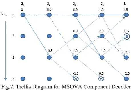
ii) The at most Nmax paths are saved at each trellis stage. If more than Nmax paths exist after pruning with threshold T, the Nmax paths with the highest path metrics are saved. The trellis diagram of modified SOVA for T = -2 and Nmax = 3 is given in figure 7.
Fig.7. Trellis Diagram for MSOVA Component Decoder for T = -2 and Nmax = 3
Here the numbers on top of each node represents paths metrics. The node obstructed by an open circle represents a path pruned using threshold T. The nodes encircled by cross indicate paths pruned using Nmax.
IV.
S
IMULATIONR
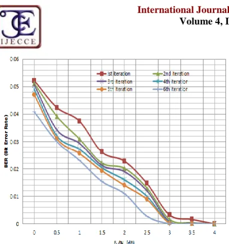
ESULTSThe proposed decoder using Modified SOVA algorithm is implemented using MATLAB. The simulation results of BER Vs. SNR for different iteration is shown in fig.8. The simulation parameter for this graph is shown in table 1.
Table 1: Parameter Used For Different Iterations
Parameters Value
Length of bit Sequence 1024
Channel Gaussian White Noise
Decoding Algorithm MSOVA
Iteration Times 1, 2, 3, 4, 5
Generator Polynomial g = [7, 5]
Copyright © 2013 IJECCE, All right reserved Fig.8. Modified SOVA algorithm for different Iterations
Table 2: Parameter Used For Different Iterations
Parameters Value
Length of bit Sequence 500, 1500
Channel Gaussian White Noise
Decoding Algorithm Modified SOVA
Iteration Times 6
Generator Polynomial g = [7, 5]
Constraint Length K=3
Fig.9. Modified SOVA algorithm for different block length
A comparison graph between the proposed algorithm and the existing LOG-MAP algorithm [11] for turbo codes is given in figure 10. The comparison graph is drawn between BER vs. SNR. The simulation parameters for the comparison are given in table 3.
Table 3: Parameter Used For Log-Map and SOVA
Parameters Value
Length of bit Sequence 1500
Channel Gaussian White Noise
Decoding Algorithm LOG-MAP, MSOVA
Iteration Times 4
Generator Polynomial g = [15, 13]
Constraint Length K = 4
Fig.10. A Comparison Graph between proposed and MAP algorithm
From the graph it can be concluded that there is an approximately 0.35db performance improvement of MSOVA over LOG-MAP at a BER of 0.069.
V.
C
ONCLUSIONR
EFERENCES[1] IEEE Std 802.16e-2005: Amendment to IEEE Std 802.16, IEEE Std., 2005.
[2] Evolved Universal Terrestrial Radio Access (E-UTRA): Multiplexing andchannel coding. 3rd Generation Partnership Project Std. 3GPP TS 36.212V8.2.0, 2008.
[3] Digital Video Broadcasting (DVB) interaction channel for satellitedistributionsystem, ETSI reference EN 301 799, v1.2.2, Dec. 2000.
[4] Framing Structure, channel coding and modulation for Satellite Services toHandheld devices (SH) below 3GHz, ETSI reference EN 302 583 V1.1.1, July2007.
[5] C. Berrou, “The Ten-Year-Old Turbo Codes are Entering intoService,” IEEE Communications Mag. vol. 41, no. 8, pp.110-116, Aug.2003.
[6] C. Berrou, A. Gliavieux, and P. Thitimajshima, “Near Shannon limiterror-correcting coding and decoding: turbo codes (1),” in Proceedings IEEE International Conference Communications, pp. 1064-1070, 1993.
[7] J. Hagenauer and P. Höher, “A Viterbi Algorithm with Soft Outputs and its Application,” in Proc. IEEE Global Communication Conference, pp.47.1.1-47.1.7, Nov. 1989. [8] Olaf J. Joeressen, Martin Vaupel, and Heinrich Meyr,
“High-SpeedVLSI Architectures for Soft-Output Viterbi Decoding,”,Proceedings IEEEInternational Conference Application Specific Array Processors, pp. 373-384, August 1992. [9] Engling Yeo, Stephanie A Augsburger, W. Rhett Davis,
BorivojeNikolic, "A 500-Mb/s Soft-Out Viterbi Decoder," in IEEE J. SolidState Circuits, Vol. 38, pp.1234-1241, July 2003.
[10] Ortin J, Garcia P, Gutierrez F and Valdovinos A., “Performance Analysis of Turbo Decoding Algorithmsin Wireless OFDM Systems,” IEEE Transaction on Consumer Electronics, Vol. 55, Issue 3, pp. 1149 – 1154, August 2009.
[11] Wang Huahua and Liu Wenwen, “Analysis of Turbo Decoding Algorithm in LTESystem,” IEEE International Conference on Fuzzy Systems andKnowledge Discovery (FSKD), pp. 1741-1744, 2012.
A
UTHOR’
SP
ROFILEMansi Rastogi
Miss Mansi Rastogi is pursuing her M.E. in Electronics and Communication Engineering from NITTTR, Chandigarh, India. She has done her B. Tech in Electronics and Communication Engineering from BIT U.P., India. Her areas of interest are Wireless Communication, Signal processing, embedded system design. Her current research is also based on Wireless Communication and Signal processing.