Adv. Radio Sci., 13, 155–159, 2015 www.adv-radio-sci.net/13/155/2015/ doi:10.5194/ars-13-155-2015
© Author(s) 2015. CC Attribution 3.0 License.
Analysis of the effect of different absorber materials and loading on
the shielding effectiveness of a metallic enclosure
S. Parr1, H. Karcoon1, S. Dickmann1, and R. Rambousky2
1Faculty of Electrical Engineering, Helmut-Schmidt-University/University of the Federal Armed Forces Hamburg, Germany 2Bundeswehr Research Institute for Protective Technologies and NBC Protection (WIS) Munster, Germany
Correspondence to: S. Parr ([email protected])
Received: 24 November 2014 – Revised: 26 February 2015 – Accepted: 4 March 2015 – Published: 3 November 2015
Abstract. Metallic rooms as part of a complex system, like a ship, are necessarily connected electromagnetically via aper-tures and cables to the outside. Therefore, their electromag-netic shielding effectiveness (SE) is limited by ventilation openings, cable feed-throughs and door gaps. Thus, elec-tronic equipment inside these rooms is susceptible to outer electromagnetic threats like IEMI1. Dielectric or magnetic absorber inside such a screened room can be used in order to prevent the SE from collapsing at the resonant frequencies. In this contribution, the effect of different available absorber materials is compared, as well as other properties like weight and workability. Furthermore, parameter variations of the ab-sorber as well as the effect of loading in form of metallic and dielectric structures on the SE are analyzed.
1 Introduction
Inside metallic, empty, perfectly conducting and cuboid rooms or enclosures, resonances are excited by external fields at the frequencies
F(m,n,p)= c 2
r m
a
2 +
n
b
2 +
p
d
2
(1) witha,bandd: dimensions,c: speed of light in free space, m, n andp: positive integers, one of which may be zero (Dawson et al., 2001). This results in large spectral and spa-tial variations in field levels up to 45 dB (Izzat et al., 1998). Electronic equipment inside the room can thus be impaired due to the high field strengths at the resonant frequencies. The SE at the resonances can be improved by lining the in-ner walls with absorbing material (Olyslager et al., 1999).
1Intentional Electromagnetic Interference
In this contribution, two studies are carried out. First, different absorber materials are compared with respect to their damping property, flammability, workability, weight and price. Therefore, a cuboid screened enclosure with di-mensions of 40 cm is analyzed in the frequency range of 400 to 1000 MHz via simulation and measurement. It is illumi-nated by a TEM wave which couples in through an aperture at its front side. The inner back side is tiled with a layer of dif-ferent absorber materials: polyurethane-carbon foam, ferrite tiles and two different types of ferrite composite absorber. The SE is determined via simulation and measurement. For the simulation, knowledge about the dielectric and magnetic properties of the absorber materials is necessary. This is pro-vided by a reflection and transmission measurement inside a coaxial transmission line.
In the second study, the SE of a full size room with a door gap as aperture is investigated numerically. As the field strength inside the resonator is spatially varying at the res-onant frequencies, the SE is calculated via the mean energy density. Different parameter variations of the absorber like thickness and number are carried out in the frequency range from 40 to 100 MHz. Furthermore, the impact of metallic and dielectric loading inside the enclosure on SE is determined.
2 Comparison of different absorbing materials
2.1 Permittivity and permeability of the absorber
per-156 S. Parr et al.: Analysis of the effect of different absorber materials
Table 1. Minimum electric shielding effectiveness of the enclosure with absorber.
Absorber ferrite polyurethane- silicon- polyethylene-
polyethylen-material carbon ferrite ferrite ferrite
(thickness) (5.5 mm) (20 mm) (2 mm) (4 mm) (2 mm)
Measurement 30 dB 24 dB 17 dB 30 dB 28 dB
Simulation 21 dB 20 dB 14 dB 34 dB 32 dB
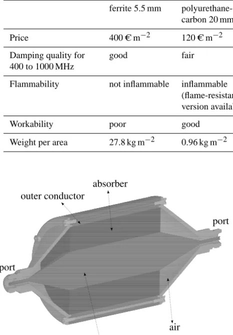
Table 2. Comparison of different properties of the absorber materials.
ferrite 5.5 mm polyurethane- silicon-ferrite polyethylene-
polyethylene-carbon 20 mm 2 mm ferrite 4 mm ferrite 2 mm
Price 400 C m−2 120 C m−2 1139 C m−2 2831 C m−2 1910 C m−2
Damping quality for 400 to 1000 MHz
good fair poor good good
Flammability not inflammable inflammable (flame-resistant version available)
not inflammable not inflammable not inflammable
Workability poor good good good good
Weight per area 27.8 kg m−2 0.96 kg m−2 6.3 kg m−2 14.8 kg m−2 7.4 kg m−2
due to the high field strengths at the resonant frequencies. The SE at the resonances can be improved
by lining the inner walls with absorbing material (Olyslager et al., 1999).
In this contribution, two studies are carried out. First, different absorber materials are compared with
respect to their damping property, flammability, workability, weight and price. Therefore, a cuboid
20screened enclosure with dimensions of 40 cm is analyzed in the frequency range of 400 to 1000 MHz
via simulation and measurement. It is illuminated by a TEM wave which couples in through an
aperture at its front side. The inner back side is tiled with a layer of different absorber materials:
polyurethane-carbon foam, ferrite tiles and two different types of ferrite composite absorber. The SE
is determined via simulation and measurement. For the simulation, knowledge about the dielectric
25and magnetic properties of the absorber materials is necessary. This is provided by a reflection and
transmission measurement inside a coaxial transmission line.
In the second study, the SE of a full size room with a door gap as aperture is investigated numerically.
As the field strength inside the resonator is spatially varying at the resonant frequencies, the SE is
calculated via the mean energy density. Different parameter variations of the absorber like thickness
30and number are carried out in the frequency range from 40 to 100 MHz. Furthermore, the impact of
metallic and dielectric loading inside the enclosure on SE is determined.
2
Comparison of different absorbing materials
2.1
Permittivity and permeability of the absorber
absorber
port
inner conductor outer conductor
port
air
Figure 1.Coaxial line experiment setup for determination of the complex permittivity.
2
Figure 1. Coaxial line experiment setup for determination of the complex permittivity.
meability εr=ε0r−j ε
00
r (2)
µr=µ0r−j µ
00
r (3)
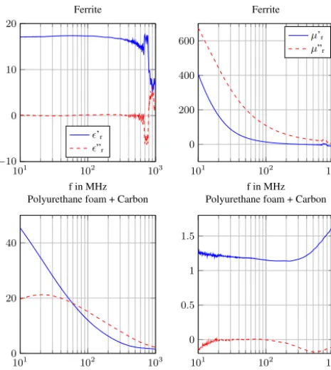
of the absorber have to be known. They are determined via a coaxial line experiment measuring the reflection and transmission coefficients with a network analyzer. The setup of the coaxial line with the absorber inserted is shown in Fig. 1. The analyzed absorber materials include polyurethane-carbon foam as an dielectric absorber, ferrite tiles, silicon-ferrite and polyethylene-ferrite as magnetic
ab-Figure 2.Absorber samples for the coaxial line experiment. From left to right: polyurethane-carbon, ferrite, silicon-ferrite, polyethylene-ferrite.
101 102 103
0 0.5 1 1.5
f in MHz
Polyurethane foam + Carbon
101 102 103
0 20 40
f in MHz
Polyurethane foam + Carbon
101 102 103
0 200 400 600
f in MHz Ferrite
µ’r µ”r
101 102 103
−10 0 10 20
f in MHz Ferrite
’r ”r
Figure 3.Permittivity and Permeability of ferrite and polyurethane-carbon absorber.
First, the influence of absorber inside a screened enclosure on the SE is analyzed for different
35
materials. In order to carry out numeric calculations, the complex permittivity and permeability
εr=ε0r−jε00r (2)
µr=µ0r−jµ00r (3)
Figure 2. Absorber samples for the coaxial line experiment. From left to right: polyurethane-carbon, ferrite, silicon-ferrite, polyethylene-ferrite.
sorber. The pre-cut absorber samples are shown in Fig. 2. The permittivity and permeability are calculated using the Nicolson-Ross-Weir (NRW) algorithm (Nicolson and Ross, 1970) from theS parameters. A measurement of the empty line yields reasonable results for permittivity and permeabil-ity of air up to 1 GHz. Above, higher order modes spoil the measurement (Ihsan et al., 2011). The extracted values for ferrite and polyurethane-carbon are shown in Fig. 3. 2.2 Shielding Effectiveness of the resonator with and
without absorber
A screened enclosure in form of a cube with dimensions of approximately 40 cm and a circular aperture with a radiusr0 of 15 mm at its front side is analyzed. The thickness of the
S. Parr et al.: Analysis of the effect of different absorber materials 157
Figure 2.Absorber samples for the coaxial line experiment. From left to right: polyurethane-carbon, ferrite, silicon-ferrite, polyethylene-ferrite.
101 102 103
0 0.5 1 1.5
f in MHz Polyurethane foam + Carbon
101 102 103
0 20 40
f in MHz Polyurethane foam + Carbon
101 102 103
0 200 400 600
f in MHz Ferrite
µ’r
µ”r
101 102 103
−10 0 10 20
f in MHz Ferrite
’r
”r
Figure 3.Permittivity and Permeability of ferrite and polyurethane-carbon absorber.
First, the influence of absorber inside a screened enclosure on the SE is analyzed for different 35
materials. In order to carry out numeric calculations, the complex permittivity and permeability
εr=ε0r−jε00r (2)
µr=µ0r−jµ00r (3)
3
Figure 3. Permittivity and Permeability of ferrite and polyurethane-carbon absorber.
Table 3. Minimum wavelength inside the absorber in the frequency range 40 to 100 MHz.
Material λminin m
vacuum 3
polyurethane-carbon 0.63
ferrite 0.069
silicon-ferrite 0.70 polyethylen-ferrite 0.38
absorber covering the inner back wall depends on the used material. The box is illuminated with a TEM wave and its electric shielding effectiveness SEelis defined as
SEel=20×log10 E0 E1
in dB. (4)
withE0: electric field in absence of the shield,E1: electric field inside the shield. SEel is determined via measurement and simulation in the frequency range of 400 MHz to 1 GHz. The lower limit is chosen in such a way that the first res-onance at 529 MHz is covered. A GTEM cell is used as a source for a TEM electromagnetic wave for the measurement (Parr et al., 2012). The simulation is done using the Finite-Element-Method within the software FEKO. The minimum of SEelof the empty resonator at the analyzed frequencies is at 10 dB. It is improved by the different absorbers reaching values shown in Table 1.
Table 2.Comparison of different properties of the absorber materials.
ferrite 5.5 mm polyurethane-carbon 20 mm
silicon-ferrite 2 mm
polyethylene-ferrite 4 mm
polyethylene-ferrite 2 mm Price 400 C/m2 120 C/m2 1139 C/m2 2831 C/m2 1910 C/m2
Damping qual-ity for 400 to 1000 MHz
good fair poor good good
Flammability not inflammable inflammable (flame-resistant
version
avail-able)
not inflammable not inflammable not inflammable
Workability poor good good good good
Weight per area
27.8 kg/m2 0.96 kg/m2 6.3 kg/m2 14.8 kg/m2 7.4 kg/m2
3 Parameter variations of the absorber and loading
3.1 Model for the numerical calculations
door crack
absorber
x y
z height
width depth
Figure 4.Screened room with door gap.
In this section, different parameter variations of the absorber geometry inside a screened room are
carried out, and the effect of dielectric and metallic structures inside is considered. Therefore, the SE 70
of a screened room with dimensions 4 m (depth) x 3 m (width) x 2.6 m (height) as shown in Figure
4 is analyzed via FEM simulation. As aperture a round about door gap is assumed, representing a
shielded door, that is not closed properly. The incoming TEM wave travels in−x- direction and its electric field is polarized 45◦ to thez- axis, in order to excite all modes. As the field levels inside
the room vary significantly in space at the resonant frequencies, the shielding effectiveness SEem is 75
5
Figure 4. Screened room with door gap.
Table 4. Minimum value for SEemwith different absorber thick-nessese.
e 0 cm 5 cm 10 cm 20 cm
SEmin −26 dB −21 dB −12 dB −2 dB
2.3 Consideration of other absorber properties
Not only the ability to improve the SE, but also other ab-sorber properties like flammability, workability, weight and price have to be considered for practical purposes. They are given for the different materials in Table 2. Ferrite has the best damping properties, but lacks workability and is heavy, whereas polyurethane-carbon absorber shows an overall de-cent performance.
3 Parameter variations of the absorber and loading
3.1 Model for the numerical calculations
In this section, different parameter variations of the absorber geometry inside a screened room are carried out, and the effect of dielectric and metallic structures inside is consid-ered. Therefore, the SE of a screened room with dimensions 4 m (depth)×3 m (width)×2.6 m (height) as shown in Fig. 4 is analyzed via FEM simulation. As aperture a round about door gap is assumed, representing a shielded door, that is not closed properly. The incoming TEM wave travels inx di-rection and its electric field is polarized 45◦ to thezaxis,
in order to excite all modes. As the field levels inside the room vary significantly in space at the resonant frequencies, the shielding effectiveness SEem is calculated via the mean energy densitywof the electromagnetic field:
SEem=10log10 w0 w1
dB (5)
158 S. Parr et al.: Analysis of the effect of different absorber materials
40 50 60 70 80 90 100
−20 0
f in MHz
SE
em
in
dB
e = 0 cm e = 5 cm e = 10 cm e = 20 cm
Figure 5.CEM results for SEemfor different polyurethane-carbon absorber thicknessese.
frequencies of the room shift slightly, as the resonator gets electrically larger. The minimum value for SEemis shown in table 5.
Table 5.Minimum value for SEemwith different number of walls lined with 10 cm absorber.
walls lined with absorber without absorber rear wall rear wall and ceiling ceiling, rear and side walls SEmin -26 dB -12 dB -6 dB -3 dB
3.3 Effect of dielectric and metallic structures inside the room
In order to distinguish between the effects of dielectric and metallic structures inside the room on SE, both cases are analyzed separately. At first, metallic structures in the form of two cuboids, named
100
here terminals, are inserted in the room model as depicted in Figure 6. The numeric results for SEem
with none, one and both terminals are shown in Figure 7. As a result, the metallic structures shift the resonant frequencies and cause additional resonances in the low frequency region.
Next, the effect of dielectric structures in form of persons is considered, that are modeled as columns with electromagnetic properties of human muscle. As a reasonable assumption, two persons are
105
modeled inside the room (Fig. 8). The numeric results in Fig. 9 show, that the (110) and (210) resonances are completely damped, because their electric field is polarized inz- direction, parallel to the columns in the centre of the room. The value for SEemat other resonances however is lower
with the dielectrics inside the room.
4 Conclusions 110
In the framework of an electromagnetic analysis of a complex system with consideration of resonant room and enclosure structures, two studies have been caried out. First, various absorber materials
7
Figure 5. CEM results for SEemfor different polyurethane-carbon absorber thicknessese.
Table 5. Minimum value for SEemwith different number of walls lined with 10 cm absorber.
walls lined without rear rear wall ceiling, rear and with absorber absorber wall and ceiling side walls
SEmin −26 dB −12 dB −6 dB −3 dB
inside the shield. It is calculated as the average value over 240 points with a spacing of 0.5 m. An adaptive frequency sampling is chosen with a minimum frequency increment of 150 kHz in the range of 40 to 100 MHz, covering the first resonance of the room at 62.5 MHz.
Due to its high permittivity and/or permeability, the ab-sorber region is meshed more densely. The minimum wave-length inside the absorber in the analyzed frequency inter-val for the different materials is shown in Table 3. Not only the absorber region is meshed densely but also the adjacent metallic surfaces of the enclosure. These are numerically solved with the Methods of Moments, which leads to high time and memory consumption in the case of ferrite. 3.2 Parameter variations of the absorber
As absorber material polyurethane-carbon is chosen. At first, the thickness of the absorber layereat the rear of the room is varied. The CEM2results for SEemfor values foreof 5, 10 and 20 cm are shown in Fig. 5. The minimum SEemwithout absorber is−26 dB at 62.5 MHz, which corresponds to the first resonance of the room (110). The resonance at 51 MHz is caused by the door gap and is therefore not affected by the absorber. SEmin, the minimum value for SEemin the analyzed frequency region for different absorber thicknesses is shown in Table 4.
Furthermore, the number of walls that are lined with ab-sorber is varied. As a result, the resonant frequencies of the room shift slightly, as the resonator gets electrically larger. The minimum value for SEemis shown in Table 5.
2Computational Electromagnetics
Figure 6.
Screened room with metallic
structures (terminals).
40
50
60
70
80
90
100
−
20
0
f in MHz
SE
em
in
dB
empty room
one terminal
two terminals
Figure 7.
CEM results for SE with and without terminals inside
the room.
Figure 8.
Screened room with
dielec-tric structures (persons).
40
50
60
70
80
90
100
−
20
0
f in MHz
SE
em
in
dB
empty room
one person
two persons
Figure 9.
CEM results for SE with and without persons inside the
room.
have been compared with respect to their effect on the SE in the frequency range of 400 to 1000 MHz.
Ferrite and a composite ferrite absorber have the best damping properties, improving the minimum
SE from 10 to 30 dB, while polyurethane-carbon foam has significant advantages in price, weight and
115
workability. Then, the effect of absorber on the resonances of a metallic room has been analyzed,
and the improvement in SE quantified with different parameter variations. It shows, that a 10 cm
polyurethane-carbon layer at the rearside of the room improves the minimum value for SE from -26
to -12 dB. Finally, the effect of loading on the resonance behavior has been considered. Metallic
structures inside the room cause additional resonances below the first room resonance, and therefore
120
reduce the SE. The effect of dielectric structures on SE depends on the electric field distribution
of the resonant modes. Both, metallic and dielectric loading, result in a slight shift of the resonant
frequencies. The results show, that the susceptibility of a complex system to an outer electromagnetic
threat in the form of IEMI can be reduced by using absorber inside the resonant structures.
Figure 6. Screened room with metallic structures (terminals).Figure 6.Screened room with metallic structures (terminals).
40 50 60 70 80 90 100 −20
0
f in MHz
SE
em
in
dB
empty room one terminal two terminals
Figure 7.CEM results for SE with and without terminals inside the room.
Figure 8.Screened room with dielec-tric structures (persons).
40 50 60 70 80 90 100 −20
0
f in MHz
SE
em
in
dB
empty room one person two persons
Figure 9.CEM results for SE with and without persons inside the room.
have been compared with respect to their effect on the SE in the frequency range of 400 to 1000 MHz.
Ferrite and a composite ferrite absorber have the best damping properties, improving the minimum
SE from 10 to 30 dB, while polyurethane-carbon foam has significant advantages in price, weight and 115
workability. Then, the effect of absorber on the resonances of a metallic room has been analyzed,
and the improvement in SE quantified with different parameter variations. It shows, that a 10 cm
polyurethane-carbon layer at the rearside of the room improves the minimum value for SE from -26
to -12 dB. Finally, the effect of loading on the resonance behavior has been considered. Metallic
structures inside the room cause additional resonances below the first room resonance, and therefore 120
reduce the SE. The effect of dielectric structures on SE depends on the electric field distribution
of the resonant modes. Both, metallic and dielectric loading, result in a slight shift of the resonant
frequencies. The results show, that the susceptibility of a complex system to an outer electromagnetic
threat in the form of IEMI can be reduced by using absorber inside the resonant structures.
8
Figure 7. CEM results for SE with and without terminals inside the room.
3.3 Effect of dielectric and metallic structures inside the room
In order to distinguish between the effects of dielectric and metallic structures inside the room on SE, both cases are an-alyzed separately. At first, metallic structures in the form of two cuboids, named here terminals, are inserted in the room model as depicted in Fig. 6. The numeric results for SEem with none, one and both terminals are shown in Fig. 7. As a result, the metallic structures shift the resonant frequencies and cause additional resonances in the low frequency region. Next, the effect of dielectric structures in form of persons is considered, that are modeled as columns with electromag-netic properties of human muscle. As a reasonable assump-tion, two persons are modeled inside the room (Fig. 8). The numeric results in Fig. 9 show, that the (110) and (210) reso-nances are completely damped, because their electric field is polarized inzdirection, parallel to the columns in the centre of the room. The value for SEemat other resonances however is lower with the dielectrics inside the room.
S. Parr et al.: Analysis of the effect of different absorber materials 159
Figure 6.
Screened room with metallic
structures (terminals).
40
50
60
70
80
90
100
−
20
0
f in MHz
SE
em
in
dB
empty room
one terminal
two terminals
Figure 7.
CEM results for SE with and without terminals inside
the room.
Figure 8.
Screened room with
dielec-tric structures (persons).
40
50
60
70
80
90
100
−
20
0
f in MHz
SE
em
in
dB
empty room
one person
two persons
Figure 9.
CEM results for SE with and without persons inside the
room.
have been compared with respect to their effect on the SE in the frequency range of 400 to 1000 MHz.
Ferrite and a composite ferrite absorber have the best damping properties, improving the minimum
SE from 10 to 30 dB, while polyurethane-carbon foam has significant advantages in price, weight and
115
workability. Then, the effect of absorber on the resonances of a metallic room has been analyzed,
and the improvement in SE quantified with different parameter variations. It shows, that a 10 cm
polyurethane-carbon layer at the rearside of the room improves the minimum value for SE from -26
to -12 dB. Finally, the effect of loading on the resonance behavior has been considered. Metallic
structures inside the room cause additional resonances below the first room resonance, and therefore
120
reduce the SE. The effect of dielectric structures on SE depends on the electric field distribution
of the resonant modes. Both, metallic and dielectric loading, result in a slight shift of the resonant
frequencies. The results show, that the susceptibility of a complex system to an outer electromagnetic
threat in the form of IEMI can be reduced by using absorber inside the resonant structures.
Figure 8. Screened room with dielectric structures (persons).4 Conclusions
In the framework of an electromagnetic analysis of a complex system with consideration of resonant room and enclosure structures, two studies have been caried out. First, various absorber materials have been compared with respect to their effect on the SE in the frequency range of 400 to 1000 MHz. Ferrite and a composite ferrite absorber have the best damping properties, improving the minimum SE from 10 to 30 dB, while polyurethane-carbon foam has significant advantages in price, weight and workability. Then, the effect of absorber on the resonances of a metallic room has been analyzed, and the improvement in SE quantified with different parameter variations. It shows, that a 10 cm polyurethane-carbon layer at the rearside of the room improves the minimum value for SE from−26 to−12 dB. Finally, the effect of loading on the resonance behavior has been considered. Metallic structures inside the room cause additional resonances below the first room resonance, and therefore reduce the SE. The effect of dielectric structures on SE depends on the electric field distribution of the resonant modes. Both, metallic and dielectric loading, result in a slight shift of the resonant frequencies. The results show, that the susceptibility of a complex system to an outer electromagnetic threat in the form of IEMI can be reduced by using absorber inside the resonant structures.
Edited by: F. Gronwald
Reviewed by: two anonymous referees
Figure 6.Screened room with metallic structures (terminals).
40 50 60 70 80 90 100
−20 0
f in MHz
SE
em
in
dB
empty room one terminal two terminals
Figure 7.CEM results for SE with and without terminals inside the room.
Figure 8.Screened room with dielec-tric structures (persons).
40 50 60 70 80 90 100
−20 0
f in MHz
SE
em
in
dB
empty room one person two persons
Figure 9.CEM results for SE with and without persons inside the room.
have been compared with respect to their effect on the SE in the frequency range of 400 to 1000 MHz.
Ferrite and a composite ferrite absorber have the best damping properties, improving the minimum
SE from 10 to 30 dB, while polyurethane-carbon foam has significant advantages in price, weight and 115
workability. Then, the effect of absorber on the resonances of a metallic room has been analyzed,
and the improvement in SE quantified with different parameter variations. It shows, that a 10 cm
polyurethane-carbon layer at the rearside of the room improves the minimum value for SE from -26
to -12 dB. Finally, the effect of loading on the resonance behavior has been considered. Metallic
structures inside the room cause additional resonances below the first room resonance, and therefore 120
reduce the SE. The effect of dielectric structures on SE depends on the electric field distribution
of the resonant modes. Both, metallic and dielectric loading, result in a slight shift of the resonant
frequencies. The results show, that the susceptibility of a complex system to an outer electromagnetic
threat in the form of IEMI can be reduced by using absorber inside the resonant structures.
8
Figure 9. CEM results for SE with and without persons inside the room.
References
Dawson, L., Dawson, J. F., Marvin, A. C., and Welsh, D.: Damp-ing resonances within a screened enclosure, IEEE Trans. Elec-tromagn. Compat., 43, 45–55, 2001.
Ihsan, Z., Lubkowski, G., Adami, C., and Suhrke, M.: Characteri-zation of the absorbing material used in EMC experiments, in: Proc. EMC Europe 2011 York, 774–777, 2011.
Izzat, N., Craddock, I. J., Hilton, G. S., and Railton, C. J.: Anal-ysis and realisation of low-cost damped screened rooms, IEE Proceedings-Science, Measurem. Technol., 145, 1–7, 1998. Nicolson, A. M. and Ross, G. F.: Measurement of the Intrinsic
Prop-erties of Materials by Time-Domain Techniques, IEEE Trans. In-strum. Meas., 19, 377–382, 1970.
Olyslager, F., Laermans, E., De Zutter, D., Criel, S., De Smedt, R., Lietaert, N., and De Clercq, A.: Numerical and experimental study of the shielding effectiveness of a metallic enclosure, Elec-tromagnetic Compatibility, IEEE Transact., 41, 202–213, 1999. Parr, S., Dickmann, S., and Rambousky, R.: Damping resonances of