ORIGINAL ARTICLE
Static Force Analysis of Foot of Electrically
Driven Heavy-Duty Six-Legged Robot
under Tripod Gait
Zhen Liu
1, Hong‑Chao Zhuang
2*, Hai‑Bo Gao
1, Zong‑Quan Deng
1and Liang Ding
1Abstract
The electrically driven six‑legged robot with high carrying capacity is an indispensable equipment for planetary exploration, but it hinders its practicability because of its low efficiency of carrying energy. Meanwhile, its load capac‑ ity also affects its application range. To reduce the power consumption, increase the load to mass ratio, and improve the stability of robot, the relationship between the walking modes and the forces of feet under the tripod gait are researched for an electrically driven heavy‑duty six‑legged robot. Based on the configuration characteristics of electri‑ cally driven heavy‑duty six‑legged, the typical walking modes of robot are analyzed. The mathematical models of the normal forces of feet are respectively established under the tripod gait of typical walking modes. According to the MATLAB software, the variable tendency charts are respectively gained for the normal forces of feet. The walk‑ ing experiments under the typical tripod gaits are implemented for the prototype of electrically driven heavy‑duty six‑legged robot. The variable tendencies of maximum normal forces of feet are acquired. The comparison results show that the theoretical and experimental data are in the same trend. The walking modes which are most available to realize the average force of distribution of each foot are confirmed. The proposed method of analyzing the rela‑ tionship between the walking modes and the forces of feet can quickly determine the optimal walking mode and gait parameters under the average distribution of foot force, which is propitious to develop the excellent heavy‑duty multi‑legged robots with the lower power consumption, larger load to mass ratio, and higher stability.
Keywords: Electrically driven, Heavy‑duty six‑legged robot, Tripod gait, Force of foot, Walking mode
© The Author(s) 2018. This article is distributed under the terms of the Creative Commons Attribution 4.0 International License
(http://creat iveco mmons .org/licen ses/by/4.0/), which permits unrestricted use, distribution, and reproduction in any medium,
provided you give appropriate credit to the original author(s) and the source, provide a link to the Creative Commons license, and indicate if changes were made.
1 Introduction
With the development of robotics, the autonomous mobile robot has been widely used [1, 2]. Intelligent [3,
4], high pass [5] and large load-ratio [6] robots have been gradually regarded as an important developing factor for the engineering of mobile robots. Based on the charac-teristics of common moving mechanisms, traditional mobile robots can be roughly divided into wheeled type, legged type, and wheel-legged type [7]. In the aspect of theoretical research and practical application, the legged robots relatively lag behind the wheeled ones [8], and the legged robots fall behind the wheeled ones in depth and
lack an extensive degree of research, especially the heavy-duty multi-legged robots. The technology parameters of the heavy-duty multi-legged robots, such as BigDog [9], Ambler [10], ATHLETE [11, 12], and Dante II [13], concludes that the heavy-duty multi-legged robots have three major characteristics comparing to the non-heavy-duty or small multi-legged robots; they are the larger vol-ume, bigger mass, and larger load to mass ratio [14].
In nature, the coordinated movement of legs is used for the legged animals to realize their walking from the current position to goal position. That coordinated movement is often called the gait. With the increase of the number of legs for legged animals and multi-legged robots, their gait types also increase, and the correspond-ing gait planncorrespond-ing method becomes more complex [15]. The conventional gait of the six-legged robot involves a tripod gait, a tetrapod gait, and a five-legged gait. The
Open Access
*Correspondence: [email protected]
2 College of Mechanical Engineering, Tianjin University of Technology and Education, Tianjin 300222, China
tripod gait is the fastest and most common for the six-legged robots and hexapod [16].
The normal force of the foot is the main component, and it is often larger than the tangential force of the foot. From the perspective of posture and balance, the main factors influencing the poses of the multi-legged robots are pitch, roll, and vertical fluctuation. The factors are directly related to the normal force of the foot on every leg [17]. From the perspective of power consumption for the mobile system of robot, the power consumption of joint is primarily confirmed by the normal force of foot. The reason is that the mass and load of robot are coun-terpoised by the normal force of foot of each leg. Hence, it shows that the normal force of foot directly affects the posture and balance of robot and power consumption of mobile system. However, the normal force of the foot var-ies when the same leg is under different walking modes or gait. The walking mode and gait of robot are inher-ently associated with the normal force of the foot. Hence, the relationship between the gait and the normal force of foot will be important for reducing the power consump-tion of mobile systems and improving the load to mass ratio and stability of heavy-duty multi-legged robots.
Based on the effective poses of robot under the quad-rangular gait, Zhuang et al. [18] presented a method to quickly obtain accurate the articulated torque by the normal force of foot for an electrically driven heavy-duty six-legged robot. The proposed method mainly involves the changes of rotational angles of the hip joint and knee joint. Li et al. [19] studied the optimal distribution of feet forces of multi-legged robots with uncertainties in both kinematics and dynamics. The analysis process is rela-tively complex because of referring to a large number of calculations and multiple algebraic derivations. Jiang et al. [20] introduced three new pseudo-inverse formula-tions for the real-time control of foot-force distribution of legged robot by avoiding foot-slip, minimizing the joint torques, and minimizing the joint work. The MAT-LAB simulation of six-legged robot is only employed to compare locomotion performance with the truly optimal foot-force distributions. Xi and Remy [21] explored the potential of trajectory optimization for unspecified con-tact sequences to identify optimal gaits and motions of legged robots. However, the proposed method was only evaluated by a 1D hopper and a 2D bipedal robot. Agheli et al. [22] presented a solution of foot force distribution based on Newton–Euler equations of motion. Elfes et al. [23] employed a virtual second order mechanical system to define the foot force in the z direction for the control of a multilegged autonomous explorer (MAX) robot. Montes and Armada [24] defined a virtual spring damper as the force of foot to evaluate the impedance control-ler of ROBOCLIMBER robot. Then, it can be found that
many researchers mainly focus on the gait or force dis-tribution for legged robots. There is less research on the relationship between the gait and the normal force of foot, especially for heavy-duty multi-legged robots.
Based on the above problems and our previous research [25–28], an electrically driven heavy-duty six-legged robot is considered to analyze its walking modes and the normal forces of its feet in different walking modes under the tripod gait. This paper is divided into six sec-tions. In Section 2, the walking modes of the electrically driven heavy-duty six-legged robot are analyzed by the configuration of the robot. In Section 3, the static anal-ysis of robot is performed. In Section 4, the theoretical analysis of the normal force of the foot is deduced in the typical walking mode under the tripod gait. In Section 5, the data of normal forces of the foot are collected from the walking experiments of the prototype under the tri-pod gait, and the experimental analysis is implemented. Then, the theoretical analysis and experimental analysis are mutually verified by comparing the theoretical cal-culation results with the experimental data for the nor-mal force of the foot under the same variable and same walking mode of the tripod gait. According to the analy-sis of the walking mode and the normal force of the foot, the walking mode which is the most favorable to carry out the walk and average force distribution of the foot is obtained, and it provides support for future research on power consumption of mobile systems. In the final sec-tion, the conclusions are presented (Additional file 1).
2 Configuration and Typical Walking Mode of Robot
2.1 Configuration of Robot
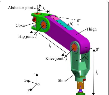
In order to facilitate appellation in this paper, the elec-trically driven heavy-duty six-legged robot is called by the heavy-duty six-legged robot for short. Based on the structure of ambulacra of the hexapod, the leg of the heavy-duty six-legged robot can be designed. A single leg contains three electric driving joints: abductor joint, hip joint, and knee joint. In addition, the axis of abductor joint follows the direction of z, and the axes of hip joint and knee joint run parallel to the y-axis. The structure of the single leg of the heavy-duty six-legged robot is shown in Figure 1. The lengths of coxa, thigh, and shin are respectively set by lc, lt, and ls. Ai, Hi, and Ki are
respec-tively regarded as the abductor joint, hip joint, and knee joint of leg i. βi′ is defined as the angle between the coxa
of leg i and the thigh of leg i, and its range is form − 90° to 90°. The angle βi, whose range is limited to 0°–150°, is
To keep the characteristics of universal walking, con-figuration of the heavy-duty six-legged robot is designed as a regular polygon. Due to the static gait for the six-leg-ged robot, the number of legs in the support phase var-ies from 3 to 6. su and tr are respectively defined as the
support phase of the legs and transfer phase of the legs rotating counterclockwise. The sets of the support phase and transfer phase are respectively defined by s= (s1, …, sk, …, su) and t= (t1, …, te, …, tr). Meanwhile, the
con-straint conditions should meet 3 ≤u≤ 6 and u+r= 6.
The mechanism and its top view of the heavy-duty six-legged robot are respectively shown in Figures 2 and 3.
In Figure 2, the body coordinate system of the robot is set by
B , and is located at the center of the body. The
principal vectors involving the gravity of the robot and principal moment are defined by FB=
FBx,FBy,FBz T
and MB=MBx,MBy,MBzT . z1(i)-axis in the abduc-tor joint coordinate system of leg i is parallel to the direction of ZB in the body coordinate system. Positive direction of the x(1i)-axis in the abductor joint coor-dinate system of leg i deviates from the coxa of leg i. The leg i lies on the plan of z1(i)x(1i) . The positive
direc-tions of the abductor joint coordinate system
Ai of leg
i and the foot coordinate system
fi of leg i are same. The positive directions of the foot’s coordinate system
oi of leg i are parallel to the positive direction of the
body’s coordinate system
B . The force of the leg sk
in support phase can be divided into BF(sk)
x , BFy(sk) , and BF(sk)
z in the coordinate system ok , and can be divided to F(fk)
x , Fy(fk) , and Fz(fk) in the coordinate system fk . The position vector of the foot at the end of the leg sk
is set by BP(sk)
F in the body coordinate system. The body coordinate system connecting leg i is defined as
0i . The coordinate system
0i and coordinate system
Ai
of abductor joint will coincide with each other when the rotating angle θi of abductor joint is zero degrees
for leg i.
In Figure 3, the 0° line is parallel to the XB axis in the body coordinate system, and it intersects with the cor-responding axes of joints. The included angle Δθi, whose
ranges is from 0° to 60°, is defined as the initial angle of the abductor joint between the 0° line and leg i, and the initial angle Δθi is used to set the initial position
of abductor joint when the robot begins to walk. θi is
defined as the rotation angle of the abductor joint of leg i from the initial angle Δθi. The initial angles Δθ2 and Δθ5 are always zero for leg 2 and leg 5 in this paper. The initial angles of abductor joints are 0°–60° for legs 1, 3, 4, and 6, and they are same when the heavy-duty six-legged robot begins to walk.
Abductor joint Knee joint t l c l s l Coxa Thigh Shin i β′ i β o 0 z y x o Hip joint o 0 − +
Figure 1 Structure of single leg of heavy‑duty six‑legged robot
3
H
3
K
Leg 1 Leg 2 Leg 3
Leg 4 Leg 5 Leg 6 1 o 2 o 3 o 4 o 5 o 6 o 1 A 2 A 3 A 4 A 5 A 6 A 1 H 1 K 6 H 6 K 4 H 4 K G Z G
Y OG
G X 2 H 2 K H5 K5 B Z B X B O B Y G ∑ B ∑
( )1 B s
z
F B ( )s1
x
F
( )1 B s y F B M B F
( )2 1
z
( )2 1
y
( )2 1
x
( )1 1
z
( )1 1
x ( )1
1
y
( )f1
z
F
( )f1
x
F ( )f1
y
F
( )3 1
z ( )3
1
y
( )3 1
x
( )4 1
z
( )4 1
y ( )4
1
x
( )5 1
x ( )5
1
z
( )5 1
y
( )6 1
z
( )6 1
x
( )6 1 y 1 f ∑ 1 o ∑
( )1 B
Fs
P
Figure 2 Mechanism of heavy‑duty six‑legged robot
Leg 1
Leg 2
Leg 3 Leg 4
Leg 5 Leg 6 l1 l2 l3 1 1 y 1 1 x 6 1 x 5 1 x 4 1 x 3 1 x 2 1 x 6 1 y 5 1 y 4 1 y 3 1 y 2 1 y 1 A 2 A 3
A A4
5 A 6 A 1 H 1 K 6 H 6 K 5 K 5 H 2 H 2 K 3 H 3 K 4 H 4 K B X B O B Y B ∑ 0º line 1 θ
∆ ∆θ6
3
θ
∆ ∆θ4
e n il º 0 e n il º 0 0º line
As shown in Figure 3, Φi is defined as the angle
between the coordinate system
0i and the coordinate
system
B for leg i. Therefore, the values of rotation
angle Φi can be 120°, 180°, 240°, 300°, 360°, and 60° for
the legs 1, 2, 3, 4, 5, and 6, respectively. Then, the fol-lowing equation can be obtained:
The matrix f
oR(i) can be deduced from the coordinate
system
Ai of abductor joint to the coordinate system
0i for leg i. Then
2.2 Typical Walking Mode of Robot
Based on the configuration of heavy-duty six-legged robot, the tripod gait contains four typical walking modes: crab type, ant type, mixture type I, and mixture type II, as shown in Figure 4. In the tripod gait of the heavy-duty six-legged robot, legs 2, 4, and 6 located at the support phase are defined as the first group, and legs 1, 3, and 5 lying in the transfer phase are defined as the second group. However, legs of the support phase are analyzed in this paper.
In Figure 4, l1, l2, and l3 are defined as straight lines, and they are respectively orthogonal to the relevant axes of the abductor joints. In order to expediently ana-lyze forces of the foot in typical walking modes of the tripod gait, the initial angles are respectively set by zero for legs 1, 2, 3, 4, 5, and 6. Meanwhile, θi is defined as
the rotating angle of the abductor joint between the leg i and 0° line under an ant-type tripod gait. θi′ is defined
as the rotating angle of the abductor joint between leg i and the 0° line under a crab-type tripod gait.
(1) B
0R(i)=Rot(z,Φi)=
cosΦi −sinΦi 0
sinΦi cosΦi 0
0 0 1
,
(2)
f oR(i)=
B
0R(i)0AR(i) −1
=(Rot(z,Φi)Rot(z,θi))T.
3 Static Analysis of Robot
The spatially parallel closed mechanism is combined by the legs of the support phase, body of robot, and ground. A passive sphere joint connects the foot and shin, and it can automatically adapt to the terrain ensuring that the foot completely contacts the ground. Hence, the moment does not exist between the ground and the foot, and the force only exists. The force analysis of heavy-duty six-leg-ged robot is shown in Figure 2. In order to simply ana-lyze, the force analysis of leg 1 is given in Figure 2. BP(s1) F is defined as the position vector in the body coordinate system
B for leg 1 in the support phase. The principal
vector of external force in robot system can be expressed as follows:
where JF is Jacobian matrix of force in the robot system,
an identity matrix of 3u×3u, BF
sk is force vector of foot in the coordinate system
B or
ok for leg sk in the support phase, BF
sk =
BF(sk)
x BFy(sk) BFz(sk)
T
, BF
s is force
matrix of the foot in the coordinate system
B for the leg in
support phase, BF
s=BFs1
BF
s2 · · ·
BF
sk · · ·
BF su
T . The expression can be written using the principal moment of external force in the robot’s system. Then
where JM is position matrix in the coordinate system B
for the leg in support phase,
(3)
u �
k=1
BF
sk=JF
BF s=
1 0 0· · · 1 0 0 0 1 0· · · 0 1 0 0 0 1· · · 0 0 1
BF(s1) x
BF(s1)
y
BF(s1) z
.. .
BF(su) x
BF(su)
y
BF(su) z
=FB,
(4) JMBFs=MB,
Leg 1
Leg 2
Leg 3 Leg 4
Leg 5 Leg 6
Moving
6 θ′
4 θ′
3 θ′
1 θ′
1
l l3
2 l
a
B X B Y
B
∑
0º line 0º line
0º line 0º line
Leg 1
Leg 2
Leg 3 Leg 4
Leg 5 Leg 6 Moving
6 θ
4 θ 3
θ 1 θ
2 θ
5 θ 1
l l3
2 l
b
B X B Y
B
∑
0º line 0º line
0º line 0º line
Leg 1
Leg 2
Leg 3 Leg 4
Leg 5 Leg 6
Moving
1 l l3
2 l
c
B X B Y
B
∑
Leg 1 Leg 2
Leg 3
Leg 4
Moving
Leg 5
Leg 6 1
l
3
l
2
l
d
B
X YB
B ∑
Based on Eqs. (3) and (4), the equilibrium matrix of generalized force can be obtained for the support phase of heavy-duty six-legged robot as follows:
where Jˆ is equivalent matrix of the foot position in the
support phase, I3×3 is the identity matrix of 3 × 3.
The force of the foot is zero when the leg is in transfer phase, and its matrix expression can be written using the body coordinate system
B . Then,
where BF
te is force vector of foot in the coordinate system
B or
ok for leg te in the transfer phase,
Based on Eqs. (5) and (6), the equilibrium matrix of general force can be written for the system of heavy-duty six-legged robot as follows:
where O is zero matrix.
Based on Figure 2 and Eq. (2), the mathematical rela-tionship of force of foot in the coordinate system
ok and the coordinate system
fk can be written for leg sk in the support phase as follows:
JM =�BP(s1)
F · · · BP
(sk)
F · · · BP
(su)
F �
,
BP(sk)
F =
0 −BP(sk)
Fz BP
(sk)
Fy
BP(sk)
Fz 0 −BP
(sk)
Fx
−BP(sk)
Fy BP
(sk)
Fx 0
.
(5)
ˆ
JBFs =
� I
3×3 I3×3 · · · I3×3 B
PF(s1) BPF(s2) · · · BP(su)
F �
B
Fs1 B
Fs2 . . . B
Fsu
= �
FB MB
� = ˆA.
(6)
BF
t=BFt1 BFt2 · · · BFte · · ·
BF
tr T
=0,
BF
te=
BF(te)
x BFy(te) BFz(te)
T
.
(7)
ˆ
J O6×3r O3r×3u I3r×3r
B
Fs BF
t
=
ˆ
A 0
.
(8)
Fx(fk) Fy(fk) Fz(fk)
=
f oR(sk)
BF(sk)
x BF(sk)
y BF(sk)
z
.
4 Force Theoretical Analysis of Foot under Gait of Robot
The normal force of the foot is generally much larger than the tangential force. The normal force of the foot is not only a key factor on influencing the position and balance of the robot as well as power consumption of the mobile system, but also a principle balance force to equilibrate the weight of the robot and its load. Thus, to easily cal-culate the normal force of the foot using the mechanical equilibrium equation, the tangential force of the foot can be ignored in the theoretical mechanical analysis of the foot force under the robot’s gait. The tripod gait is a com-mon gait, and it is also the fastest gait for the six-legged robot. In this section, the normal force of the foot in the support phase is only analyzed under the tripod gait, and the step pitch and initial angle are changing.
For the same leg in the support phase, its normal force varies under the same gait and different terrain. It shows that the terrain affects the value of the foot’s normal force, and it is difficult to reproduce the same relation between the gait and the normal force of the foot in com-plex terrain for the same supporting leg. That is to say, the values of the normal forces of the foot are difference when the robot repetitiously traverses the same terrain under the same gait. However, it is difficult to obtain the real relation between the gait and the normal force of the foot. Hence, the flat ground is used to research the rela-tion above, and it is useful to lay the foundarela-tion for ana-lyzing that relation on the complex terrain.
The walking speed keeps stable when the heavy-duty six-legged robot linearly walks. The distance of the mass center of body to the ground is a constant. The foot’s pro-jective tracks for every leg and mass center of the body are parallel to each other. It is assumed that the robot cannot bear the additional principal vector and princi-pal moment expect for the masses of robot and cargoes. Then, the principal vector and principal moment of robot should meet:
where mL is the mass of the robot, mR is the mass of cargo carried by the robot.
The tripod gait is used for the heavy-duty six-legged robot. Then, the support phase involves legs 2, 4, and 6, and the transfer phase involves legs 1, 3, and 5. The nor-mal force of the foot in the support phase is restricted by the mass mL of the robot and mass mR of cargo. When (9)
FB
MB
=
the tangential force of the foot is ignored, the expression can be obtained for the normal force of the foot in the support phase as follows:
Based on Eq. (5), the equilibrium matrix of general forces in the support phase can be deduced for the heavy-duty six-legged robot as follows:
Equations (4), (9), and (10) are respectively substituted into Eq. (11), and the equilibrium equations of robot can be deduced as follows:
When the heavy-duty six-legged robot begins to walk, the initial angles of abductor joints are equal for legs 1, 3, 4, and 6, and the initial angles of abductor joints of legs 2 and 5 are set as the zero degrees. Therefore, the relations of the initial angles are Δθ1 = Δθ3 = Δθ4 = Δθ6 and Δθ2 = Δθ5 = 0°. L′pi is defined as the projective length of leg i in the support phase on the ground, and it is the initial offset. To simplify the analysis, the variables Δθ and L′ps are introduced. Then, the following mathematical relationships can be obtained:
4.1 Theoretical Analysis of Normal Force of Foot under Ant‑type Tripod Gait
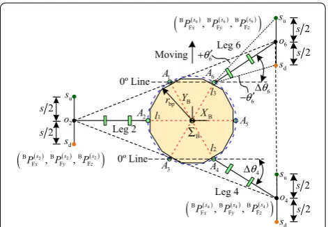
The support phase is shown in Figure 5, and the ant-type tripod gait is used for the heavy-duty six-legged robot. In Figure 5, the robot walks along the direction of YB axis. su and sd are respectively defined as the upper point and lower point for the legs in support phase. The distance from su to sd is defined by s, and it is also the step pitch in this paper. The coordinate of foot is expressed by BP(sk)
Fx ,BP
(sk)
Fy ,BP
(sk)
Fz
in the body coordinate system
B for leg sk.
Based on Figure 5, the coordinates of the legs’ feet in the support phase can be obtained along the x direction of the body coordinate system
B as follows:
(10) BF s2 BF s4 BF s6 T
=�0 0BFz(s2) 0 0BFz(s4) 0 0BFz(s6)
� .
(11) ˆ
JBFs=
�
I3×3 I3×3 I3×3 BP(s2)
F BP
(s4) F BP
(s6) F � BF s2 BF s4 BF s6 = � FB MB � . (12)
BF(s2)
z +BFz(s4)+BFz(s6)=mLg+mRg, BP(s2)
Fy BF (s2)
z +BPFy(s4)BF (s4)
z +BP(Fys6)BF (s6) z =0, BP(s2)
Fx BF (s2)
z +BPFx(s4)BF (s4)
z +BP(Fxs6)BF (s6) z =0.
(13)
�θ1=�θ3=�θ4=�θ6=�θ,
L′P2=L′P4=L′P6=L′PS.
When the body of the robot walks forward using step pitch s, the foot in the support phase relatively moves back distance s. The gravity center of the robot and sup-port points of the legs respectively move from the upper point su to the lower point sd. Then, the coordinates of the feet at the lowest point sd can be respectively deduced along the y direction in the body coordinate system
B for legs 2, 4, and 6; they are shown as follows:
Equations (14) and (15) can be substituted into Eq. (12). The mathematical models of the normal forces of feet can be respectively deduced for the legs 2, 4, and 6. Then
where (14)
BP(s2)
Fx = − �
rbp+L′P2 �
,
BP(s4)
Fx =rbpcos 60◦+L′P4cos(�θ4), BP(s6)
Fx =rbpcos 60◦+L′P6cos(�θ6).
(15)
BP(s2)
Fy = −s
�
2,
BP(s4)
Fy = −
�
rbpsin 60◦+L′P4sin(�θ4)�−s�2, BP(s6)
Fy =
�
rbpsin 60◦+L′P6sin(�θ6)�−s�2.
(16)
BF(s2)
z = rbp+2L ′ PScos(�θ )
Q3
�
mLg+mRg�
,
BF(s4)
z = QQ13×−QQ24�mLg+mRg�, BF(s6)
z = QQ31+×QQ24�mLg+mRg�.
Q1=�
rbp+L′PS��√
3rbp+2L′PSsin(�θ )�, Q2=�
3rbp�
2+L′PS+L′PScos(�θ )�s, Q3=3rbp+2LPS′ +2L′PScos(�θ ), Q4=√3rbp+2L′PSsin(�θ ).
Leg 2 Leg 4 Leg 6 l1 l2 l3 1 A 2 A 3
A A4
5 A 6 A B X B Y
Moving o6
4 o 2 o bp r u s d s u s d s u s d s 6 θ ∆ 4 θ ∆ 0º Line 0º Line 6 θ ′ + 6 θ ′ − 2 s 2 s 2 s 2 s 2 s 2 s ( ) ( ) ( )
(
B 2 B 2 B 2)
Fxs , Fys , Fzs
P P P
( ) ( ) ( )
(
B 4 B 4 B 4)
Fxs , Fys , Fzs
P P P
( ) ( ) ( )
(
B 6 B 6 B 6)
Fxs , Fys , Fzs
P P P
B
∑
When the feet in the support phase are located at the upper point su for legs 2, 4, and 6, their coordinates along the y direction in body coordinate
B can be obtained by
changing the s to −s in Eq. (15), and their normal forces can be also obtained by setting s to the −s in Eq. (16). Then, the mathematical models of the normal forces of the feet are not given for legs 2, 4, and 6 in this paper.
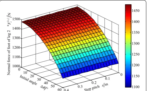
The step pitch s, height of body h, and initial offset L′PS are respectively set by 0.4 m, 0.5 m, and 0.68 m for the heavy-duty six-legged robot, when the feet in the support phase move from the upper point su to the lower point sd. The ranges of the initial angles of the abductor joints are from 0° to 60° for legs 1, 3, 4, and 6. The radius rbp of the body is introduced in Eq. (16). Then, MATLAB soft-ware is used to compile programs for analyzing the nor-mal forces of feet of the support phase under the ant-type tripod gait. The variable tendency charts of the normal forces of feet are obtained and respectively shown in Fig-ures 6, 7, and 8 for legs 2, 4, and 6.
Based on Figure 6, the normal force of the foot of leg 2 gradually decreases from 1478 N to 1098 N, when the initial angle Δθ of abductor joint varies from 0° to 60°. The normal force of the foot of leg 2 is a constant with a change of step pitch s. When the initial angle Δθ of the abductor joint is 20°, the normal force of the foot is about 1442 N for leg 2.
Based on Figure 7, with the initial angle Δθ varying from 0° to 60°, it shows that the variable tendency of the foot’s normal force overall presents from augmentation to a decrease for the leg 4, when the step pitch s is between 0 m to 0.2 m. In addition, the normal force of the foot of leg 4 gradually increases when the step pitch s is between 0.2 m to 0.4 m. It also shows that the normal force of the foot overall decreases for leg 4, when the initial angle Δθ is a fixed value and the range of step pitch s is from 0 m to 0.4 m. For the foot’s normal force of leg 4, the maximum
value is 1858 N when the step pitch s and initial angle Δθ are zero, and the minimum value is 45.62 N when the step pitch s is 0.4 m and the initial angle Δθ is 3°.
Based on Figure 8, with the initial angle Δθ varying from 0° to 60°, it shows that the variable tendency of the normal force of the foot overall presents from a decrease to aug-mentation for the leg 6, when the step pitch s is between 0.2 m to 0.4 m. The normal force of the foot of leg 6 gradu-ally increases when the step pitch s is between 0 m to 0.2 m. It can be found that the normal force of the foot increases overall for leg 6, when the initial angle Δθ is a fixed value and the range of step pitch s is from 0 m to 0.4 m. For the foot’s normal force of leg 6, its maximum value is 1858 N when the step pitch s and initial angle Δθ are zero, its mini-mum value is 45.62 N when the step pitch s is 0 m and the initial angle Δθ is 3°, and its value is 1098 N when the step pitch s is 0.2 m and the initial angle Δθ is 60°.
According to Figures 6, 7, and 8, the curves of the max-imum normal forces of feet are obtained for legs 2, 4, and 6 with the varying of the initial angle Δθ and step pitch
0 0.1 0.2 0.3 0.4 0
10 20
30 40
50 60 1000
1100 1200 1300 1400 1500
1100 1150 1200 1250 1300 1350 1400 1450
()2
B
N
s z
F
θ
∆ °
Initial angle
Normal force of foot of leg
2
Step pitch m s
Figure 6 Variable tendency chart of normal force of foot for leg 2 with changes in Δθ and s under ant‑type tripod gait
0 0.1 0.2 0.3 0.4 0
10 20
30 40
50 60 0
500 1000 1500 2000
200 400 600 800 1000 1200 1400 1600 1800
()4
B
N
s z
F
θ
∆ °
Initial angl e
Normal force of foot of leg
4
Step pitc h sm
Figure 7 Variable tendency chart of normal force of foot for leg 4 with changes in Δθ and s under ant‑type tripod gait
0 0.1
0.2 0.3
0.4
0 10 20 30 40 50 600 500 1000 1500 2000
200 400 600 800 1000 1200 1400 1600 1800
()6
B
N
s z
F
θ
∆ °
Initial angle
Normal force of foot of leg
6
Step pitc h sm
s. When s= 0.4 m and 20° ≤ Δθ≤ 60°, the curves of the maximum normal forces of feet are shown in Figure 9. When 0.1 m ≤s≤ 0.4 m and Δθ= 20°, the curves of the maximum normal forces of feet are shown in Figure 10. When 0.1 m ≤s≤ 0.4 m and Δθ= 60°, the curves of the maximum normal forces of feet are shown in Figure 11.
According to Figure 9, when the step pitch s is 0.3 m and the initial angle Δθ varies from 20° to 60°, it can be found that the maximum normal force of the foot of leg 2 gradually reduces, and the maximum normal forces of feet are from augmentation to a decrease for the legs 4 and 6.
Based on Figure 10, when the step pitch s varies from 0.1 m to 0.4 m and the initial angle Δθ is 20°, it shows that the maximum normal force of the foot is a con-stant for the leg 2, and the maximum normal forces of feet gradually decreases for the legs 4 and 6.
According to Figure 11, when the step pitch s changes from 0.1 m to 0.4 m and the initial angle Δθ is 60°, it can be found that the maximum normal force of the foot remains constant for the leg 2, the maximum nor-mal force of the foot first decreases, then increases, and finally decreases for leg 4, and the maximum normal force of the foot of leg 6 varies from augmentation to a decrease.
4.2 Theoretical Analysis of Normal Force of Foot under Crab‑type Tripod Gait
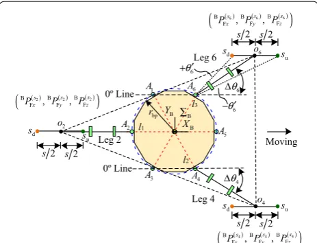
The robot in support phase is shown in Figure 12, when the crab-type tripod gait is employed for the heavy-duty six-legged robot. As shown in Figure 12, the robot walks along the XB axis in the body coordinate system.
Based on Figure 12, the feet’s coordinates in the sup-port phase can be obtained along the y direction of the body coordinate system
B . Then
(17)
BP(s2)
Fy =0,
BP(s4)
Fy = −
�
rbpsin 60◦+L′P4sin(�θ4) �
,
BP(s6)
Fy =
�
rbpsin 60◦+L′P6sin(�θ6)�.
20 30 40 50 60
1050 1100 1150 1200 1250 1300 1350 1400 1450
( )2 B
z
F
( )4 B
z
F
( )6 B
z
F
()
B
Maxi
mu
m
norma
l forces of feet
N
i z
F
Initial angle of abductor joint /º
Figure 9 Curves of maximum normal forces of feet under s= 0.4 m, 20° ≤ Δθ≤ 60°, and ant‑type tripod gait
0.10 0.15 0.20 0.25 0.30 0.35 0.40
1000 1100 1200 1300 1400 1500 1600
Step pitch s/m
( )2 B
z
F
( )4 B
z
F
( )6 B
z
F
()
B
Maxi
mu
m
norm
al forces of feet
N
i z
F
Figure 10 Curves of maximum normal forces of feet under 0.1 m ≤s≤ 0.4 m, Δθ= 20°, and ant‑type tripod gait
0.10 0.15 0.20 0.25 0.30 0.35 0.40
1000 1050 1100 1150 1200 1250
( )2 B
z
F
( )4 B
z
F
( )6 B
z
F
Step pitch s/m
()
B
Maxi
mu
m
normal forces of feet
N
i z
F
When the body of the robot walks forward with a step pitch s, the foot of the leg in support phase relatively moves back a distance s. That is to say, the support points of the legs respectively move from the upper point su to the lower point sd. Then, the coordinates of the feet at the lower point sd can be respectively obtained along the x direction in the body coordinate system
B for legs 2, 4,
and 6; they are shown as follows:
Equations (17) and (18) can be substituted into Eq. (12), and the mathematical models of the normal forces of the feet can be respectively deduced for legs 2, 4, and 6. Then
When the feet in support phase for legs 2, 4, and 6 are located at the upper point su,, their coordinates along the x direction in the body coordinate
B can be obtained
with changing s to −s in Eq. (18), and their normal forces
of the feet can be also obtained by setting s to −s in Eq.
(19). In addition, the mathematical models of the normal forces of the feet are not given for legs 2, 4, and 6 in this paper. Based on Eq. (19), it can be found that the normal (18)
BP(s2)
Fx = −
�
rbp+L′P2
�
− 2s, BP(s4)
Fx =rbpcos 60◦+L′P4cos(�θ4)−2s, BP(s6)
Fx =rbpcos 60◦+L′P6cos(�θ6)− s2.
(19)
BF(s2)
z =
�
rbp+2L′PScos(�θ )−s
�
(mLg+mRg)
3rbp+2L′PS+2L′PScos(�θ ) ,
BF(s4)
z =
�
rbp+L′PS+s/2
�
(mLg+mRg)
3rbp+2L′PS+2L′PScos(�θ ) ,
BF(s6)
z =
�
rbp+L′PS+s/2
�
(mLg+mRg)
3rbp+2L′PS+2L′PScos(�θ ) .
force of the foot of leg 4 is equal to the normal force of the foot of leg 6 under the crab-type tripod gait.
The step pitch s, height h of the body, and initial offset L′PS are respectively set by 0.4 m, 0.5 m, and 0.68 m for the heavy-duty six-legged robot, when the feet in support phase move from the upper point su to the lower point sd. The ranges of the initial angles of abductor joints are from 0° to 60° for legs 1, 3, 4, and 6. The radius rbp of body is introduced into Eq. (19). Then, the MATLAB software is employed to analyze the normal forces of the feet in the support phase under the ant-type tripod gait. The variable tendency charts of the normal forces of the feet are obtained and respectively shown in Figures 13 and 14
for legs 2, 4, and 6.
Based on Figures 13 and 14, the curves of the maximum normal forces of feet are respectively obtained for legs 2, 4, and 6 with the initial angle Δθ and step pitch s vary-ing. When s= 0.2 m and 0° ≤ Δθ≤ 60°, the curves of the maximum normal forces of feet are shown in Figure 15. When 0.05 m ≤s≤ 0.2 m and Δθ= 0°, the curves of the maximum normal forces of feet are shown in Figure 16. When 0.1 m ≤s≤ 0.4 m and Δθ= 60°, the curves of the maximum normal forces of feet are shown in Figure 17.
Based on Figure 13, it shows that the normal force of the foot decreases for leg 2, when the step pitch s is a fixed value and the range of initial angle Δθ is from 0° to 60°, or when the initial angle Δθ is a fixed value and the range of step pitch s is from 0 m to 0.4 m. The foot’s maxi-mum normal force of leg 2 is 1814 N, when the step pitch s and the initial angle Δθ are 0 m and 0°, respectively. The foot’s minimum normal force of leg 2 is 691.1 N, when the step pitch s is 0.4 m and the initial angle Δθ is 60°. The foot’s normal force for leg 2 is 1098 N, when the step pitch s is 0 m and the initial angle Δθ is 60°.
Based on Figure 14, it shows that the normal forces of legs 4 and 6 increase, when the step pitch s is a fixed value Leg 2
Leg 4 Leg 6
l1
l2
l3 1
A
2
A
3
A A4 5
A
6
A
B
X
B
Y
Moving 6
o
4
o
2
o rbp
u
s
d
s
u
s
d
s
u
s
d
s
6
θ
∆
4
θ
∆
0º Line
0º Line
6
θ′ +
6
θ′ −
2 s s2
2 s s2
2 s s2
( ) ( ) ( )
(
B 2 B 2 B 2)
Fxs , Fys , Fzs
P P P
( ) ( ) ( )
(
B 4 B 4 B 4)
Fxs , Fys , Fzs
P P P
( ) ( ) ( )
(
B 6 B 6 B 6)
Fxs , Fys , Fzs
P P P
B
∑
Figure 12 Support phase of heavy‑duty six‑legged under crab‑type tripod gait
0 0.1 0.2 0.3 0.4 0 10
20 30
40 50 60
600 800 1000 1200 1400 1600 1800 2000
800 1000 1200 1400 1600 1800
()2
B
N
s z
F
θ ∆ °
Initial angle
Normal force of foot of leg
2
Step pitch ms
and the range of initial angle Δθ is from 0° to 60°, or when the initial angle Δθ is a fixed value and the range of step pitch s is from 0 m to 0.4 m. The minimum normal forces of feet are 739.2 N for leg 4 and leg 6, when the step pitch s and initial angle Δθ are 0 m and 0°, respectively. The maximum normal forces of feet are 1301 N, when the step pitch s is 0.4 m and the initial angle Δθ is 60°. The normal forces of feet are 1098 N for leg 4 and leg 6, when the step pitch s is 0 m and the initial angle Δθ is 60°.
Based on Figure 15, when the step pitch s is 0.2 m and the initial angle Δθ varies from 0° to 60°, it shows that the maximum normal force of the foot gradually decreases for leg 2, and gradually increases for leg 4 and leg 6, respectively. The maximum normal forces of the feet are equal to each other for legs 2, 4, and 6, when the initial angle Δθ is 60°.
According to Figure 16, when the initial angle Δθ is 0° and the step pitch s varies from 0.05 m to 0.2 m, it shows that the maximum normal forces of feet gradually increase
for legs 2, 4, and 6. And the curves of the maximum nor-mal forces of the feet are the same for leg 4 and leg 6.
Based on Figure 17, when the initial angle Δθ is 60° and the step pitch s varies from 0.1 m to 0.4 m, it can be con-cluded that the variable tendency of the maximum nor-mal force of the foot augments then decreases for leg 2. And the maximum normal forces of the feet are equal and gradually increase with the change of the step pitch for leg 4 and leg 6.
5 Force Experimental Analysis of Foot under Robotic Gait
Based on the previous achievements in the scientific research, the prototype of electrically driven heavy-duty six-legged robot was developed. Its load to mass ratio is more than 0.46. The walking experiments of prototype are implemented under four kinds of typical tripod gaits on a flat ground. In addition, the walking experiments of the mixture-type II walking mode are shown in Fig-ure 18. The force experimental analysis of the foot is not
0 0.1
0.2 0.3
0.4
0 10 20 30 40 50 60 600 800 1000 1200 1400
800 900 1000 1100 1200 1300
()4/6
B
N
s z
F
Normal forces of feet of legs
4a
nd
6
θ
∆ °
Initial angle
Step pitch m s
Figure 14 Variable tendency charts of normal forces of feet for legs 4 and 6 with changes in Δθ and s under crab‑type tripod gait
0 10 20 30 40 50 60
900 1000 1100 1200 1300 1400 1500 1600
()
B
Maximu
m
norm
al forces of feet
N
i z
F
Initial angle of abductor joint /º
( )2 B
z
F
( )4 B
z
F
( )6 B
z
F
Figure 15 Curves of maximum normal forces of feet under s= 0.2 m, 0° ≤ Δθ≤ 60°, and crab‑type tripod gait
0.05 0.075 0.10 0.125 0.15 0.175 0.20
900 1000 1100 1200 1300 1400 1500 1600 1700
Step pitchs/m
()
B
Maximum norm
al forces of feet
N
i z
F
( )2 B
z
F
( )4 B
z
F
( )6 B
z
F
Figure 16 Curves of maximum normal forces of feet under 0.05 m ≤s≤ 0.2 m, Δθ= 0°, crab‑type tripod gait
0.10 0.15 0.20 0.25 0.30 0.35 0.40
1100 1120 1140 1160 1180 1200 1220 1240 1260
1280 B ( )2
z
F
( )4 B
z
F
( )6 B
z
F
Step pitchs/m
()
B
Maxi
mu
m
nor
mal
forces of feet
N
i z
F
only able to verify the correctness of the force theoreti-cal analysis, but is also helpful to further analyze the rela-tions between the gait and the normal force of feet.
Three walking periods are respectively set for the heavy-duty six-legged robot in walking experiments of the tripod gait. The six-dimension force/torque sensors are employed to collect the normal forces of the feet for all six legs in real time, and the maximum normal forces of the feet are col-lected for every leg. The curves of the maximum normal forces of the feet for the six legs are respectively obtained with the change in the step pitch and initial angle of the abductor joint. While the experimental and theoretical results of the variable tendencies of the maximum normal forces are the same, it can be concluded that the experi-mental data is correct, and the theoretical analysis is rea-sonable. When the four kinds of typical tripod gaits are used for the walking experiments, the initial offset L′pi is set by 0.68 m, and the mass mR of cargo is set by 0 kg.
5.1 Force Experimental Analysis of Foot under Ant‑type Tripod Gait
5.1.1 Changing Initial Angle
When the heavy-duty six-legged robot walks along the YB direction in the body coordinate system under the ant-type tripod gait, the initial angles of abductor joints vary from 20° to 60° for legs 1, 3, 4, and 6, and the initial angles are 0° for leg 2 and leg 5. In addition, the body height h and step pitch s are 0.5 m and 0.3 m, respectively. The variable tendency of the maximum normal force BF(i)
z of
the foot of leg i can be obtained with the change in the initial angle, as shown in Figure 19.
Figure 19 shows that the maximum normal forces for the feet of leg 2 and leg 5 gradually decrease with the change in the initial angle, and their variable tendencies are equal. When the initial angle is 20°, the maximum normal forces of the feet for leg 2 and leg 5 are larger than the other maximum normal forces of the feet. When the
initial angle is 60°, the minimum difference exists among the maximum normal forces of the feet. Based on Fig-ures 9 and 19, it is concluded that the variable tendencies of the feet’s maximum normal forces are respectively cor-responding to the same for legs 2, 4, and 6, when the step pitch is 0.3 m and the initial angle varies from 20° to 60°.
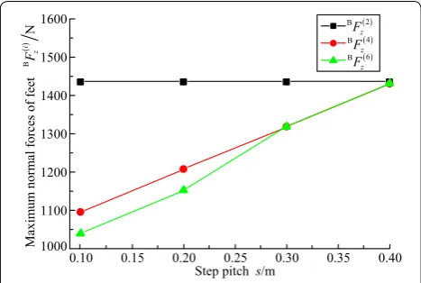
5.1.2 Changing Step Pitch
Without losing the generality, the initial angles are set by 20° for legs 1, 3, 4, and 6, and set by 0° for leg 2 and leg 5, when the heavy-duty six-legged robot walks along the YB direction in the body coordinate system under the ant-type tripod gait. In addition, the body height h keeps 0.5 m, and the step pitch s varies from 0.1 m to 0.4 m. The variable tendency of the maximum normal force BF(i)
z of
the foot of leg i can be obtained with the change in the step pitch, as shown in Figure 20.
Figure 18 Walking experiments of mixture‑type II walking mode 20 25 30 35 40 45 50 55 60 1000
1100 1200 1300 1400 1500
()
B
Maximum normal force of foot
N
i z
F
Initial angle of abductor joint i/º
( )1 B
z
F ( )2 B
z
F ( )3 B
z
F
( )4 B
z
F ( )5 B
z
F ( )6 B
z
F
Figure 19 Variable tendencies of maximum normal forces of feet with change in initial angle under ant‑type tripod gait
0.10 0.15 0.20 0.25 0.30 0.35 0.40
1000 1100 1200 1300 1400 1500
( )1 B
z
F
( )2 B
z
F
( )3 B
z
F
( )4 B
z
F
( )5 B
z
F
( )6 B
z
F
Step pitch s/m
()
B
Maximu
m
norm
al force of foot
N
i z
F
Based on Figure 20, with the step pitch varying from 0.1 m to 0.4 m, it is concluded that the curves of the max-imum normal forces of feet keep stable for leg 2 and leg 5, and they are over other curves. According to Figure 20, it can be found that the force distribution is easier to real-ize when the step pitch has a larger value. Based on Fig-ures 10 and 20, it can also be concluded that the variable tendencies of the maximum normal forces of the feet are respectively corresponding to the same for legs 2, 4, and 6, when the initial angle is 20° and the step pitch varies from 0.1 m to 0.4 m.
5.2 Force Experimental Analysis of Foot under Crab‑type Tripod Gait
5.2.1 Changing Initial Angle
When the heavy-duty six-legged robot walks along the XB direction in the body coordinate system under the crab-type tripod gait, the initial angles of the abduc-tor joints vary from 0° to 60° for legs 1, 3, 4, and 6, and the initial angles are 0° for leg 2 and leg 5. In addition, the body height h and step pitch s keep 0.5 m and 0.2 m, respectively. The variable tendency of the maximum nor-mal force BF(i)
z of the foot of leg i can be obtained with
the change in the initial angle, as shown in Figure 21. Based on Figure 21, it shows that the curves of the max-imum normal forces of the feet present a gradually down-ward trend for leg 2 and leg 5, and gradually rising trends for the other legs, with the initial angle varying from 0° to 60°. When the initial angle is in between 0° and 50°, the maximum normal forces of the feet of leg 2 and leg 5 are greater than the maximum normal forces of the feet of other legs. The maximum normal forces of the feet are approximately equal to each other, when the initial angle is 60°. Based on Figures 15 and 21, it can be found that the variable tendencies of the maximum normal forces
of the feet are respectively corresponding to the same for legs 2, 4, and 6, when the step pitch is 0.2 m and the ini-tial angle varies from 0° to 60°.
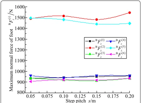
5.2.2 Changing Step Pitch
Without losing the generality, the initial angles are set by 0° for legs 1, 2, 3, 4, 5, and 6, when the heavy-duty six-legged robot walks with the ant-type tripod gait along the XB direction in the body coordinate system. In addi-tion, the body height h keeps 0.5 m, and the step pitch s is between 0.05 m and 0.2 m. The variable tendency of the maximum normal force BF(i)
z of the foot of leg i can
be obtained with the change in the step pitch, as shown in Figure 22.
Based on Figure 22, with the step pitch varying from 0.05 m to 0.2 m, it can be concluded that the curves of the maximum normal forces of the feet are mostly uni-form for leg 2 and leg 5, for leg 3 and leg 4, and for leg 2 and leg 5, respectively. Meanwhile, the maximum normal forces of leg 2 and leg 5 are greater than other legs’ maxi-mum normal forces. Figure 22 shows that the maximum normal forces of the feet gradually increase with the step pitch varying for legs 1, 2, 3, 4, and 6. Based on Figures 16
and 22, it can be concluded that the variable tendencies of maximum normal forces of the feet are respectively corresponding to the same for legs 2, 4, and 6, when the initial angle is 0° and the step pitch varies from 0.05 m to 0.2 m.
5.3 Force Experimental Analysis of Foot under Mixture‑type I Tripod Gait
When the heavy-duty six-legged robot walks using the mixture-type I tripod gait along the XB direction in the body coordinate system, the initial angles are all 60° for
0 10 20 30 40 50 60
900 1000 1100 1200 1300 1400 1500
1600 B ( )1
z
F ( )2 B
z
F ( )3 B
z
F
( )4 B
z
F ( )5 B
z
F ( )6 B
z
F
Initial angle of abductor joint i/º
()
B
Maxi
mu
m
norm
al force of foot
N
i z
F
Figure 21 Variable tendencies of maximum normal forces of feet with change in initial angle under crab‑type tripod gait
800 900 1000 1100 1200 1300 1400 1500 1600
( )1 B
z
F ( )2 B
z
F ( )3 B
z
F
( )4 B
z
F ( )5 B
z
F ( )6 B
z
F
()
B
Maxi
mu
m
norm
al force of foot
N
i z
F
0.05 0.075 0.10 0.125 0.15 0.175 0.20
Step pitch s/m
legs 1, 3, 4, and 6, and initial angles are all 0° for leg 2 and leg 5. In addition, the body height h keeps 0.5 m, and the step pitch s ranges between 0.1 m and 0.4 m. The variable tendency of the maximum normal force BF(i)
z of the foot
of leg i can be obtained with the change in the step pitch, as shown in Figure 23.
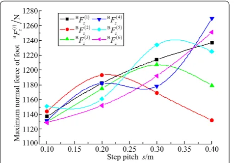
Based on Figure 23, it can be concluded that the devia-tions of maximum normal forces of the feet become larger with the step pitch increasing from 0.1 m to 0.4 m. According to Figures 17 and 23, it can be found that the variable tendencies of maximum normal forces of the feet correspond uniformly for legs 2, 4, and 6, respectively, when the initial angle is 60° and the step pitch ranges between 0.1 m to 0.4 m.
5.4 Force Experimental Analysis of Foot under Mixture‑type II Tripod Gait
When the heavy-duty six-legged robot walks using the mixture-type II tripod gait along the YB direction in body coordinate system, the initial angles are all 60° for legs 1, 3, 4, and 6, and initial angles are all 0° for leg 2 and leg 5. In addition, the body height h keeps 0.5 m, and the step pitch s ranges between 0.1 m and 0.4 m. The variable ten-dency of the maximum normal force BF(i)
z of foot of leg
i can be obtained with the change in the step pitch, as shown in Figure 24.
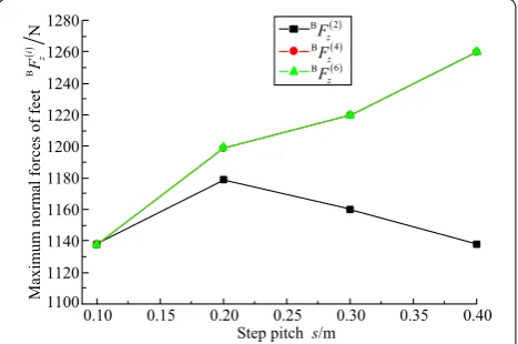
Based on Figure 24, with the step pitch ranging from 0.1 m to 0.4 m, it can be concluded that the curve of the maximum normal force of the foot approximately keeps stable for leg 2. The variable tendency of the maximum normal force of foot presents from decrease to augmen-tation for leg 4; the variable tendency shows adverse to leg 6’s. According to Figures 11 and 24, it can be found that the variable tendencies of the maximum normal forces of the feet are respectively corresponding to the
same for legs 2, 4, and 6, when the initial angle is 60° and the step pitch ranges between 0.1 m to 0.4 m.
5.5 Amplitude Interval Analysis of Normal Force of Foot under Gait of Robot
Based on the analysis above, it can be obtained that the results of theoretical and experimental data keep consist-ent in the aspect of the maximum normal force of the foot. Hence, it can be concluded that the reasonableness and correctness can be respectively obtained for the force theoretical analysis of the foot and experimental data under four kinds of typical tripod gaits of heavy-duty six-legged robots.
To further analyze the characteristics of normal forces of the feet, the range of maximum normal force of the foot is defined, it is a difference between the maximum value and the minimum value in the figure, and its sym-bol is set as RF. Based on Figures 19, 20, 21, 22, 23, and
24, the ranges of maximum normal forces of the feet are respectively obtained under four kinds of typical tripod gaits, as shown in Table 1. Which the range of maximum normal force of the foot is the least among the walking modes, it can be found that the force distribution is the most easily achieved under that walking mode.
Based on Table 1, it is concluded that the mixture-type I has the least range of maximum normal force of the foot. In the aspect of force distribution, it can be obtained that the ant-type tripod gait is better than the crab-type tripod gait, and the mixture-type I tripod gait is better than the mixture-type II tripod gait. Therefore, the hexapod mostly chooses the ant-type walking mode rather than the crab-type walking mode.
According to Figure 4, it can be found that the walk-ing speed of the heavy-duty six-legged robot depends on the hip joints and knee joints of leg 2 and leg 5, not Step pitchs/m
0.10 0.15 0.20 0.25 0.30 0.35 0.40
1100 1120 1140 1160 1180 1200 1220 1240 1260 1280
( )1 B
z
F
( )2 B
z
F
( )3 B
z
F
( )4 B
z
F
( )5 B
z
F
( )6 B
z
F
()
B
Maxi
mu
m
norm
al force of foot
N
i z
F
Figure 23 Variable tendencies of maximum normal forces of feet with change in step pitch under mixture‑type I tripod gait
( )1 B
z
F
( )2 B
z
F
( )3 B
z
F
( )4 B
z
F
( )5 B
z
F
( )6 B
z
F
0.10 0.15 0.20 0.25 0.30 0.35 0.40
1080 1110 1140 1170 1200 1230 1260
Step pitchs/m
()
B
Maxi
mu
m
norm
al force of foot
N
i z
F
on their abductor joints. When the actuating devices are confirmed and need to provide large torque, the hip joints and knee joints of leg 2 and leg 5 limits the walking speed of the robot. Hence, the mixture-type II walking mode is better than the mixture-type I walking mode in the aspect of walking speed.
Based on the analysis above, it can be concluded that the mixture-type I and mixture-type II walking modes are better than the ant type and crab type in the aspect of the force distribution and stability. Furthermore, it can be obtained that the mixture-type II walking mode is the best and should be preferentially employed for the heavy-duty six-legged robot with the consideration of walking speed. Actually, the reasonable walking mode can be used based on the practical requirements of the heavy-duty six-legged robot, and it can be concluded that the maximum walking speed of robot is easily achieved by the ant-type walking mode. The limited space can be traversed using the crab-type walking mode. The force distribution and stability can be easily realized using the mixture-type I walking mode and mixture-type II walk-ing mode.
6 Conclusions
(1) Four kinds of typical walking modes are obtained based on the configuration of root. The variable ten-dency charts of normal forces of the feet are described with the changes in the initial angle and step pitch by performing the theoretical analysis of static foot force. (2) According to the walking experiments of robot proto-type under four kinds of typical tripod gaits, the vari-able tendencies of the maximum normal forces of feet are respectively obtained with the changes in the ini-tial angle and step pitch. The comparison results show that the theoretical and experimental data are in the same trend under the same variable and same walking mode of the tripod gait.
(3) The optimal walking mode, the mixture-type II walk-ing mode, is confirmed, and it is firstly recommended for the electrically driven heavy-duty six-legged robot in view of its excellent characteristics in walking speed, stability, force distribution, and load to mass ratio.
Additional file
Additional file 1: Brief introduction of the article.
Authors’ Contributions
ZL and H‑CZ was in charge of the whole trial; H‑CZ wrote the manuscript; H‑CZ, H‑BG, Z‑QD, and LD assisted with sampling and laboratory analyses. All authors read and approved the final manuscript.
Author details
1 State Key Laboratory of Robotics and System, Harbin Institute of Technology, Harbin 150080, China. 2 College of Mechanical Engineering, Tianjin University of Technology and Education, Tianjin 300222, China.
Authors’ Information
Zhen Liu, born in 1983, is currently a lecturer at State Key Laboratory of Robotics and System, Harbin Institute of Technology, China. He received his PhD degree from Harbin Institute of Technology, China, in 2013. His research interests include planetary rover technology and aerospace mechanisms and control.
Hong‑Chao Zhuang, born in 1982, is currently a lecturer at College of Mechanical Engineering, Tianjin University of Technology and Education, China. He received his PhD degree from Harbin Institute of Technology, China, in 2015. His research interests include special robot systems and intelligent robotics.
Hai‑Bo Gao, born in 1970, is currently a professor and a supervisor for PhD candidates at State Key Laboratory of Robotics and System, Harbin Institute of Technology, China. He received his PhD degree from Harbin Institute of Technol-ogy, China, in 2004. His research interests include special robot systems and aerospace mechanisms and control.
Zong‑Quan Deng, born in 1956, is currently a professor and a supervisor for PhD candidates at Harbin Institute of Technology, China. He received his master’s degree from Harbin Institute of Technology, China, in 1984. His research interests include planetary rover technology and aerospace mechanisms and control.
Liang Ding, born in 1980, is currently a professor and a supervisor for PhD candidates at State Key Laboratory of Robotics and System, Harbin Institute of Technology, China. He received his PhD degree from Harbin Institute of Technol-ogy, China, in 2009. His research interests include planetary rover technology and aerospace mechanisms and control.
Competing Interests
The authors declare no competing financial interests.
Funding
Supported by National Natural Science Foundation of China (Grant Nos. 51505335, 51275106), and National Basic Research Program of China (973 Program, Grant No. 2013CB035502).
Publisher’s Note
Springer Nature remains neutral with regard to jurisdictional claims in pub‑ lished maps and institutional affiliations.
Received: 1 August 2016 Accepted: 2 August 2018 Table 1 Ranges of maximum normal forces of feet
under four kinds of typical tripod gaits
Walking modes Ranges of maximum normal forces
of feet RF/N
Change in initial angle Change
in step pitch
Ant type 370 432
Crab type 614.5 638.4
Mixture type I – 141
![Figure 4 Four kinds of typical tripod gaits of heavy‑duty six‑legged robot [26] (a crab type; b ant type; c mixture type I; d mixture type II)](https://thumb-us.123doks.com/thumbv2/123dok_us/9593506.1941853/4.595.67.540.579.690/figure-typical-tripod-gaits-heavy-legged-mixture-mixture.webp)