www.adv-radio-sci.net/4/293/2006/ © Author(s) 2006. This work is licensed under a Creative Commons License.
Advances in
Radio Science
On the synthesis and optimization of cascaded continuous-time
Sigma-Delta modulators
M. Keller, A. Buhmann, M. Kuderer, and Y. Manoli
Chair of Microelectronics, Department of Microsystems Engineering (IMTEK), University of Freiburg, Georges-Koehler-Allee 102, D-79110 Freiburg, Germany
Abstract. Up to now, there exist two completely different approaches for the synthesis of cascaded CT Sigma-Delta modulators. While the first method is based on a DT pro-totype and thus on the application of a DT-to-CT transforma-tion, the second one is entirely performed in the CT domain. In this contribution, the method of lifting will be applied to overcome the disadvantages afflicted with the first method (e.g. less ideal anti-aliasing filter performance, increased cir-cuit complexity) and to establish a time efficient DT simula-tion model for the second method. Thereby, optimal modula-tor coefficients as well as optimal digital cancellation filters for an arbitrary cascaded CT modulator can be simulated in an efficient and rapid manner. For illustrative purposes, the complete synthesis procedure is demonstrated by the exam-ple of a 2-1-1 cascaded CT modulator.
1 Introduction
Owning to their inherent robustness to most circuit non-idealities afflicted with deep-submicron CMOS technologies, the concept of Sigma-Delta A/D conversion has proven it-self as a very efficient technique for the implementation of A/D converters in such technologies over the last decades. While their classical field of application is found in low to medium bandwidth with medium to high resolutions such as telephone or audio, nowadays, they have to deal with ever-growing bandwidth standards altogether with the demand for higher or even adjustable resolution as it may be imposed by video or broadband data communication applications.
For several reasons, especially the principle of cascaded continuous-time (CT) Sigma-Delta modulators seems to be a most promising concept for such applications. Compared to a single stage realization of the same overall modulator order N(N ≥3), they achieve a higher resolution (Marques et al., Correspondence to: M. Keller ([email protected])
1998). This benefit stems from the a priori stability of such modulators when only first and second order modulators are used in the cascade, which enables a noise-shaping filter be-havior more closely to the one of an ideal high-pass filter of the same order. Moreover, the resolution of cascaded archi-tectures can simply be adjusted by switching on or off several stages in the cascade which makes them very attractive for multi-standard adaptive circuits (Rodr´iguez-V´azquez, 2005). Compared to DT realizations, CT modulators show the ad-vantage of a lower power consumption due to their lower bandwidth requirements for their operational amplifiers. Fi-nally, any CT modulator offers an intrinsic anti-aliasing filter, thus giving it the additional advantages of reduced die area and further power savings compared to DT realizations.
After a short introduction to the state-of-the-art techniques for the synthesis of cascaded CT modulators and their af-flicted drawbacks in the next Section, the method of lifting will be introduced using the example of a CT 2-1-1 modula-tor to overcome these drawbacks.
2 State-of-the-art techniques
2.1 DT-to-CT transformation
addi-294 M. Keller et al.: On the synthesis and optimization of cascaded CT Sigma-Delta modulators
y[n] k113
x(t) k I(s)
2 k I(s)1
k112 k123 k122 k13 k12
k213 k23
DCF2 x (t)1 x (t)2
x (t)3
DCF1 y [n]1
DAC1
fS
y [n]2
DAC2
fS
DCF3 y [n]3
DAC3
fS
x (t)4 k I(s)3
k I(s)4
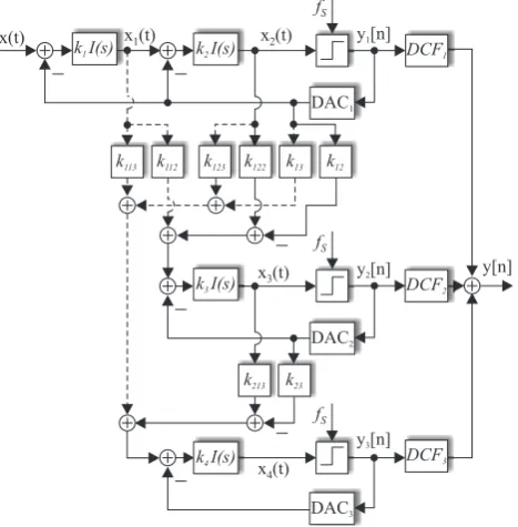
Fig. 1. Continuous-time 2-1-1 modulator based on the classical DT architecture (solid) and as obtained from a DT-to-CT transformation (including dashed signal paths).
tional signal paths (Fig. 1, dashed lines) are needed in order to enable the DT-to-CT transformation. Other than the men-tioned drawback of increased circuit complexity (Tortosa et al., 2005), it has been shown that due to the direct connection from the first stage to the third stage viak113, the high fre-quency behavior of the signal transfer functionST F (s)and therewith the anti-aliasing feature is given by Keller et al. (to be published):
ST F (s)≈k1k113k4 f
s s
2DCF 3[z] LF3[z]
z=es/fs (1) wherefs/s represents the integrator transfer functionI (s), DCF3[z] the digital cancellation filter andLF3[z] the loop filter of the last stage, respectively. The magnitude of the STF together with its approximation for high frequency input signals according to Eq. (1) is shown in Fig. 2 (dashed line vs. dashdot line). All CT coefficients have been derived via a DT-to-CT transformation of the DT coefficients given in Marques et al. (1998).
2.2 Direct synthesis
To overcome the drawback of increased circuit complexity afflicted with the DT-to-CT transformation, it has been pro-posed to skip the additional signal paths, which are solely needed to make the DT-to-CT transformation possible, and rather to re-adjust the digital cancellation filters (Tortosa et al., 2005). The first step toward that end is to trans-y[n] k113
x(t) k I(s)
2 k I(s)1
k112 k123 k122 k13 k12
k213 k23
DCF2 x (t)1 x (t)2
x (t)3
DCF1 y [n]1
DAC1 fS
y [n]2
DAC2 fS
DCF3 y [n]3
DAC3 fS
x (t)4 k I(s)3
k I(s)4
Fig. 1.Continuous-time 2-1-1 modulator based on the classical DT architecture (solid) and as obtained from a DT-to-CT transformation (including dashed signal paths).
connection from the first stage to the third stage via k113,
the high frequency behavior of the signal transfer function
ST F(s)and therewith the anti-aliasing feature is given by
(Keller et al., to be published):
ST F(s)≈k1k113k4
fs
s
2
DCF3[z]
LF3[z]
z=es/fs (1)
wherefs/srepresents the integrator transfer functionI(s),
DCF3[z]the digital cancellationfilter andLF3[z]the loop
filter of the last stage, respectively. The magnitude of the STF together with its approximation for high frequency in-put signals according to (1) is shown in Fig.2 (dashed line vs. dashdot line). All CT coefficients have been derived via a DT-to-CT transformation of the DT coefficients given in (Marques et al., 1998).
2.2 Direct Synthesis
To overcome the drawback of increased circuit complexity afflicted with the DT-to-CT transformation, it has been pro-posed to skip the additional signal paths, which are solely needed to make the DT-to-CT transformation possible, and rather to re-adjust the digital cancellation filters (Tortosa et al., 2005). The first step toward that end is to trans-form the given modulator into its mathematical representa-tion as shown in Fig.3. A detailed descriprepresenta-tion to this ap-proach is given in (Keller et al., to be published). Replacing the strongly nonlinear quantizers by their linear white noise models and transforming every conglomerate of DAC, CT loop-filter LF or CT connecting loop-filter CLF and sampler
−20 −40 −60 −80 −100 −120 0
0 0.5 1 1.5 2 2.5 3
f/fs STF STF approx. sinc4 | STF(f) | [dB]
Fig. 2.Signal transfer function of the CT 2-1-1 modulator shown in Fig.1 with and without additional signal paths (dashed line vs. solid line) and approximation of the former by (1) (dashdot line).
to its DT equivalent allows for each noise transfer function, i.e. the transfer function from one quantization error to the outputy[n], to be entirely calculated in thez-domain.
There-with, the digital cancellationfilter can be adjusted in the tra-ditional manner, namely to cancel the quantization errors of all stages but the last. Furthermore, the overall noise trans-fer function related to the quantization error of the last stage should result in an ideal high-passfilter whose order is equal to the overall modulator order, i.e. the sum of the orders of all single stage modulators in the cascade, while maintaining a DC gain of one for the signal transfer function.
The application of this method overcomes the drawback of increased circuit complexity. Moreover, the resulting signal transfer function is equal to an ideal fourth order sinc-filter and therewith offers a superior anti-aliasing feature com-pared to the approach of the DT-to-CT transformation (Fig.2, solid line vs. dashed line). However, it is detrimental in that one still has to resort to time consuming CT simulations. This becomes even more apparent whenever optimal coeffi -cients as well as optimal digital cancellationfilters for any cascaded CT architecture have to be found or to be verified by simulation.
3 Lifting
To obtain a fast but yet precise DT simulation model for any CT cascaded modulator, the method of lifting is introduced using the example of the CT 2-1-1 modulator without addi-tional signal paths in Fig.1. Toward that end, the state space description of this modulator has to be found. Assuming a sample frequency equal to one and following the notations in Fig.1 and Fig.4, the state space description of this multiple input and multiple output system results in:
Fig. 2. Signal transfer function of the CT 2-1-1 modulator shown in Fig.1 with and without additional signal paths (dashed line vs. solid line) and approximation of the former by Eq. (1) (dashdot line).
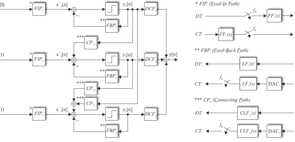
form the given modulator into its mathematical representa-tion as shown in Fig. 3. A detailed descriprepresenta-tion to this ap-proach is given in Keller et al. (to be published). Replacing the strongly nonlinear quantizers by their linear white noise models and transforming every conglomerate of DAC, CT loop-filter LF or CT connecting loop-filter CLF and sampler to its DT equivalent allows for each noise transfer function, i.e. the transfer function from one quantization error to the outputy[n], to be entirely calculated in thez-domain. There-with, the digital cancellation filter can be adjusted in the tra-ditional manner, namely to cancel the quantization errors of all stages but the last. Furthermore, the overall noise trans-fer function related to the quantization error of the last stage should result in an ideal high-pass filter whose order is equal to the overall modulator order, i.e. the sum of the orders of all single stage modulators in the cascade, while maintaining a DC gain of one for the signal transfer function.
LF zi[ ]
**FBPi( eed- ack ath)F B P
DT:
CT: LF s)i( DACi fS
*FIPi( eed- n ath)F I P
CT: F (s)Fi
fS
DT: F zFi[ ] fS
y[n]
DCF1
y [n]2
DCF2
y [n]3
DCF3
y [n]1
CP12
CP13 CP23
x (t)1
x (t)2
x (t)3
**
***
FIP1
*
**
** *
*
FIP2
FIP3
FBP1
FBP2
FBP3
***
*** ***CPij( onnecting ath)C P
DT: CLF zij[ ]
CT: CLF s)ij( fS
DACi
x´ [n]1 x (t)1
x´ [n]2
x´ [n]3
Fig. 3. System theoretical approach for a DT or CT modulator realized as a cascade of three single stage modulators possessing arbitrary orders. Allxi(t )are equal to the input signalx(t )- generally applied to the first stage of the cascade only - and may therefore be shorted.
DCF2 x(t) = u (t)1
DCF1 y (t)1
DAC1
fS
DAC2
DCF3 DAC3
u (t)2
u (t)3
u (t)4
y (t)2
y (t)3
y[n] State
Space Description
A B C D
( )
Fig. 4. State space representation of a cascaded CT modulator com-posed of three single stage modulators possessing arbitrary orders.
3 Lifting
To obtain a fast but yet precise DT simulation model for any CT cascaded modulator, the method of lifting is introduced using the example of the CT 2-1-1 modulator without addi-tional signal paths in Fig. 1. Toward that end, the state space description of this modulator has to be found. Assuming a sample frequency equal to one and following the notations in Figs. 1 and 4, the state space description of this multiple input and multiple output system results in:
˙
X(t)=A X(t)+B U (t)
Y (t)=C X(t)+D U (t) (2)
with
A=
0 0 0 0
k2 0 0 0
0 k122k3 0 0 0 0 k213k4 0
C=
0 1 0 0 0 0 1 0 0 0 0 1
B=
k1 −k1 0 0
0 −k2 0 0
0 −k12k3 −k3 0 0 0 −k23k4−k4
D=0 (3)
The DT state space description is then easily obtained as (Ya-mamoto, 1999):
X[n+1]=eAX[n]+ Z 1
0
eA(1−τ )BU[n](τ )dτ
Y[n]=CX[n] (4)
U[n](τ ) is a vector containing the lifted input signals to the state space system block, each defined as a sequence of functions:
L:u7→ {u[n](τ )}∞ n=0, u[n](τ )=u(n+τ ),
296 M. Keller et al.: On the synthesis and optimization of cascaded CT Sigma-Delta modulators
DCF1[z]=
(k1+12b1k1+4)z3+(11k1+12−12b1k1)z2+(11k1−12−12b1k1)z+k1+12b1k1−4 24k1z4
DCF2[z]=
(2b2+1)z3−(6b2+1)z2+(6b2−1)z+1−2b2 2c1z4
DCF3[z]=
(1−z−1)3 c1c2
(6)
DCF1[z] = (k1+ 12b1k1+ 4)z 3+ (11k
1+ 12−12b1k1)z2+ (11k1−12−12b1k1)z+k1+ 12b1k1−4 24k1z4
DCF2[z] = (2b2+ 1)z 3−(6b
2+ 1)z2+ (6b2−1)z+ 1−2b2
2c1z4 DCF3[z] = (1
−z−1)3
c1c2 (6)
In order to validate the correctness of the application of lift-ing, exemplary simulations have been performed on the lifted model of the 2-1-1 modulator in Fig.1 tofind optimal values for the connecting coefficientsk112,k12,k213andk23. More
precisely, these connecting coefficients have been substituted byc1/(k1k2),c1b1,c2/k3andc2b2and the new coefficients
bi andci have been optimized. Although beyond the scope of this paper, this allows for a direct comparison with the op-timal DT connecting coefficients as presented in (Marques et al., 1998). Note that already a parametric sweep over these four coefficients between 0.1 and 2 with a step width of 0.1 results in 160000 simulations. In this context, a set of coeffi -cients is defined as optimal in case that the highest signal-to-noise-and-distortion ratio (SNDR) within a signal bandwidth
fbof 1/32 (OSR 16,fs1) is achieved using a sine wave input signal with an amplitude of 0.7 times the reference voltage of the DAC and a frequency offb/4. The remaining
coef-ficients k1 to k4 (2/3, 3/8, 1/2, 1/2) have been chosen
ac-cording to a DT-to-CT transformation of the DT coefficients given in (Marques et al., 1998). For the reason of simplicity, only NRZ digital-to-analog converters have been used. The digital cancellation filters given in (6) are obtained by cal-culations using effective quantizer gains of1/(k1k2)in the
first stage, 1/k3 in the second stage and1/k4 in the third
stage, respectively. With the obtained coefficientsb1,b2,c1
andc2(9/10, 1/5, 1/5, 11/10), simulations concerning the
dy-namic range of the modulator have been performed on both the original modulator and its lifted model. Obviously, the results shown in Fig.5 are almost identical and therewith do
10 20 30 40 50 60 70
0
0 −70 −60 −50 −40 −30 −20 −10
Original CT 2-1-1 Modulator Lifted CT 2-1-1 Model
Input Amplitude / Vref [dB]
SNDR
[dB]
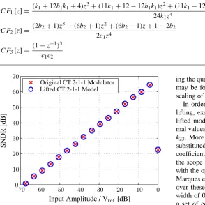
Fig. 5.SNDR of the CT 2-1-1 modulator, simulated on the original modulator (x-mark) and its lifted model (o-mark).
confirm the correctness of the lifting approach.
4 Conclusions
In this contribution, it has been shown that cascaded CT mod-ulators based on the classical DT architecture, i.e. feeding the quantization error to the next stage only, have two important advantages over those derived by DT prototypes: reduced circuit complexity and superior anti-aliasingfilter behavior. The drawback of long simulation runtime afflicted with be-havioral models of cascaded CT modulators was overcome by the application of lifting to the CT modulator. Time
ef-ficient simulations can then be performed on the equivalent DT model with almost identical results. However, lifting is thus far only applied to the simulation of ideal modulators. The embedding of non-idealities such asfinite opamp gain or even jitter in these simulations will further improve both the quality and the profitableness of this method.
References
Marques, A., Peluso, V., Steyaert, M. S. and Sansen, W. M.:
Opti-mal Parameters for∆ΣModulator Topologies, IEEE Trans.
Cir-cuits Syst. II, vol. 45, no. 9, pp. 1232-1241, Sep. 1998.
Rodr´ıguez-V´azquez, A.: UsingΣ∆ Converters for
Communica-tions and their Application to Multi-Standard Receivers part of
Multi-Standard Adaptive Circuits and Systems for Wireless Com-munications, Half Day Tutorial, Int. Sym. on Circuits and Sys-tems, Kobe, Japan, 2005.
Ortmanns, M., Gerfers, F. and Manoli, Y.: On the Synthesis of
Cascaded Continuous-TimeΣ∆Modulators, in Proc. IEEE Int.
Symp. on Circuits and Systems, 2001, pp. 419-422.
Medeiro, F., P´erez-Verd´u, B. and Rodr´ıguez-V´azquez, A.:
Top-Down Design Of High-Performance Sigma-Delta Modulators, Dordrecht, The Netherlands: Kluwer Academic Publishers, 1999.
Cherry, J. A. and Snelgrove, W. M.: Continuous-Time Delta-Sigma Modulators for High-Speed A/D Conversion, Norwell, MA: Kluwer Academic Publishers, 2000.
Tortosa, R., de la Rosa, J. M., Rodr´ıguez-V´azquez, A. and
Fern´andez, F. V.: A Direct Synthesis Method of Cascaded Continuous-Time Sigma-Delta Modulators, in Proc. IEEE Int. Symp. on Circuits and Systems, 2005, pp. 5585-5588.
Keller, M., Buhmmann, A., Ortmanns, M., Gerfers, F. and Manoli, Y.: On the Implicit Anti-Aliasing Feature of Continuous-Time Multistage Noise-Shaping Sigma-Delta Modulators, IEEE Trans. Circuits Syst. I, to resubmit after revision.
Yamamoto, Y.: Digital Control, Wiley Encyclopedia of Electrical and Electronics Engineering, vol. 5, pp. 445-457, 1999
Schreier, R. and Temes, G. C.: Understanding Delta-Sigma Data Converters, Piscataway, NJ: IEEE Press, 2005.
Fig. 5. SNDR of the CT 2-1-1 modulator, simulated on the original modulator (x-mark) and its lifted model (o-mark).
Unlike the classical DT state space transformation, which assumes the input signalsui(t )to be constant over one sam-pling interval, this approach allows for arbitrary waveforms of both the input signal as well as the feedback signals. With regard to the mathematical modelling of cascaded CT Sigma-Delta modulators, the former has its justification only in case of a DC input signal in combination with non-return-to-zero (NRZ) DAC output signals while it is erroneous for every other type of input or DAC output signal.
The only condition to be fulfilled for an efficient imple-mentation of this model in a simulator like MATLAB is im-posed by the integral in Eq. (4) to be solvable in closed form. Since usually criteria like stability, dynamic range or achiev-able signal-to-noise-ratio are determined by applying a sine wave input signal to the modulator (Schreier et al., 2005), troubles in solving the integrals may only be encountered de-pending on the choice of the DAC signal waveforms.
The application of lifting to the CT modulator thus results in an exact DT state space representation of the CT modula-tor. This in turn allows for fast and yet precise DT simula-tions to be performed without paying the penalty of loosing the inter-sampling behavior of the CT system and therewith loosing the information of the exact states of the state space variables. In this way optimal coefficients for a cascaded CT modulator based on the traditional DT architecture, i.e.
feed-ing the quantization error of one stage to the next stage only, may be found by resorting to fast simulations. Moreover, scaling of the state space variables can easily be performed.
In order to validate the correctness of the application of lifting, exemplary simulations have been performed on the lifted model of the 2-1-1 modulator in Fig. 1 to find opti-mal values for the connecting coefficientsk112,k12,k213and k23. More precisely, these connecting coefficients have been substituted byc1/(k1k2),c1b1,c2/ k3andc2b2and the new coefficientsbiandcihave been optimized. Although beyond the scope of this paper, this allows for a direct comparison with the optimal DT connecting coefficients as presented in Marques et al. (1998). Note that already a parametric sweep over these four coefficients between 0.1 and 2 with a step width of 0.1 results in 160000 simulations. In this context, a set of coefficients is defined as optimal in case that the highest signal-to-noise-and-distortion ratio (SNDR) within a signal bandwidthfbof 1/32 (OSR 16,fs 1) is achieved us-ing a sine wave input signal with an amplitude of 0.7 times the reference voltage of the DAC and a frequency offb/4. The remaining coefficientsk1tok4(2/3, 3/8, 1/2, 1/2) have been chosen according to a DT-to-CT transformation of the DT coefficients given in Marques et al. (1998). For the rea-son of simplicity, only NRZ digital-to-analog converters have been used. The digital cancellation filters given in Eq. (6) are obtained by calculations using effective quantizer gains of 1/(k1k2)in the first stage, 1/ k3in the second stage and 1/ k4 in the third stage, respectively. With the obtained coefficients b1,b2,c1andc2(9/10, 1/5, 1/5, 11/10), simulations concern-ing the dynamic range of the modulator have been performed on both the original modulator and its lifted model. Obvi-ously, the results shown in Fig. 5 are almost identical and therewith do confirm the correctness of the lifting approach.
4 Conclusions
effi-cient simulations can then be performed on the equivalent DT model with almost identical results. However, lifting is thus far only applied to the simulation of ideal modulators. The embedding of non-idealities such as finite opamp gain or even jitter in these simulations will further improve both the quality and the profitableness of this method.
Acknowledgements. This work was supported by Deutsche Forschungsgemeinschaft (German Research Foundation) under grant MA 2193/6-1.
References
Marques, A., Peluso, V., Steyaert, M. S., and Sansen, W. M.: Opti-mal Parameters for16Modulator Topologies, IEEE Trans. Cir-cuits Syst. II, 45, 1232–1241, 1998.
Rodr´iguez-V´azquez, A.: Using61Converters for Communica-tions and their Application to Multi-Standard Receivers part of Multi-Standard Adaptive Circuits and Systems for Wireless Communications, Half Day Tutorial, Int. Sym. on Circuits and Systems, Kobe, Japan, 2005.
Ortmanns, M., Gerfers, F., and Manoli, Y.: On the Synthesis of Cascaded Continuous-Time61Modulators, in Proc. IEEE Int. Symp. on Circuits and Systems, 419–422, 2001.
Medeiro, F., P´erez-Verd´u, B., and Rodr´iguez-V´azquez, A.: Top-Down Design Of High-Performance Sigma-Delta Modulators, Dordrecht, The Netherlands: Kluwer Academic Publishers, 1999.
Cherry, J. A. and Snelgrove, W. M.: Continuous-Time Delta-Sigma Modulators for High-Speed A/D Conversion, Norwell, MA: Kluwer Academic Publishers, 2000.
Tortosa, R., de la Rosa, J. M., Rodr´iguez-V´azquez, A., and Fern´andez, F. V.: A Direct Synthesis Method of Cascaded Continuous-Time Sigma-Delta Modulators, in Proc. IEEE Int. Symp. on Circuits and Systems, 5585–5588, 2005.
Keller, M., Buhmmann, A., Ortmanns, M., Gerfers, F., and Manoli, Y.: On the Implicit Anti-Aliasing Feature of Continuous-Time Multistage Noise-Shaping Sigma-Delta Modulators, sub-mitted to IEEE Trans. Circuits Syst. I.
Yamamoto, Y.: Digital Control, Wiley Encyclopedia of Electrical and Electronics Engineering, 5, 445–457, 1999.