49
Copyright © 2016. Vandana Publications. All Rights Reserved.
Volume-6, Issue-6, November-December 2016
International Journal of Engineering and Management Research
Page Number: 49-55
Fuzzy Based Control Scheme for H-Bridge Multilevel PV Inverter with
Individual MPPT Control in 3-Phase Grid-Connected Applications
Prasanna Lakshmi B1, J.Suresh2
1PG Scholar, Department of EEE, Audisankara college of Engineering &Tech., Autonomous, Gudur, Nellore(dt),AP, INDIA 2
Professor & HOD, Department of EEE, Audisankara college of Engineering &Tech., Autonomous, Gudur, Nellore(dt),AP, INDIA
ABSTRACT
This paper proposed Fuzzy based control scheme for H-Bridge multilevel PV inverter with individual MPPT control in 3-phase grid connected applications. This type of inverter topology helps to increase the flexibility and efficiency of PV systems. For better operation of PV modules and increase the solar power extraction, an individual MPPT control scheme is applied to 3-phase multilevel inverters at each phase, it will allows independent control of each dc-link voltage. Due to PV panel mismatches, it produce an unbalanced delivered power, which leads to unbalanced grid current in 3-phase grid-connected applications. In order to solve this problem, a fuzzy based control scheme with modulation compensation is proposed. Simulation results are presented to verify the possibility of the proposed approach by using MATLAB SIMULINK model design.
Keywords— H-Bridge Multilevel inverter, Maximum Power Point Tracking, Fuzzy, PV modules
I.
INTRODUCTION
Solar energy is an alternate energy resource or an energy-resource complementary in hybrid systems have been becoming possible due to the increase of research and development work in this area. In order to make best use of the PV systems, a reasonable cost, a high reliability, and a user-friendly design must be achieved in the proposed PV topologies. Several standards given by the utility companies must be obeyed in the PV-module connection. Nowadays, the standards EN61000-3-2 [1], IEEE1547 [2], and the U.S. National Electrical Code (NEC) 690 [3] are being considered. These standards deal with issues like power quality, detection of islanding operation, grounding, etc. They define the structure and the features of the present and future PV modules. In this paper cascaded H-Bridge multilevel inverter are proposed it is shown in Fig1.Cascaded inverters involves several converters connected in series, thus, the high power and high voltage extract from the combination of the multiple modules. This topology would favor in large and medium grid-connected PV systems [12]-[14]. Each PV module has its own dc/ac converter, and the modules with their connected
converters are connected in series to generate a high dc voltage, which is provided to a simplified dc/ac electrical converter. This system is combined topologies of series inverters and ac-module inverters and offers the benefits of individual maximum power point (MPP) tracking (MPPT), but the main advantage of this method is less costly and more efficient than ac-module inverters.
Fig: 1.Cascade H-Bridge Multilevel Inverter
However, there are two power conversion stages in this configuration. Here each PV panel is connected to each dc/ac inverter and it creates one module, those modules are placed in series to generate a high-voltage level [17]-[20]. The benefits of this cascaded inverter are ―one converter per panel,‖ for better utilization per PV module. In addition, this dc/ac cascaded inverter eliminates the necessity of per-string dc bus and the central dc/ac inverter, which further increases the overall efficiency. In this topology multilevel inverter requires an isolated dc source for each H-bridge inverter. The separate DC links are used in the multilevel inverter, it creates an individual voltage control. As a result, individual MPPT control in each PV module can be achieved, and it extracts maximum quantity of energy from PV panels. Meanwhile, the modularity and low cost of multilevel electrical converters locate them as a major issue for the future generation for efficient and reliable grid connected solar power electronics.
3-50
Copyright © 2016. Vandana Publications. All Rights Reserved.
phase modular cascaded multilevel inverter topology has been assembled. Each inverter is connected to one solar panel. This modular design will increases the efficiency and flexibility of the system and it is very economical. The H-bridge inverter is connected to the grid through L filters, for reduction of switching harmonics in the current. Simulation results are provided to establish the developed control scheme.
II.
SYSTEM DESCRIPTION
Topology of the modular cascaded H-bridge multilevel inverter for three-phase grid-connected PV systems shown in Fig-2
Fig: 2.The modular cascaded H-bridge multilevel PV inverter for 3-phase grid applications
‘n’ H-bridge inverters are connected in series per phase , and dc link of each H-bridge can be fed by a solar panel. This modular design is connected to the grid through L filters, it is used to decrease the switching harmonics in the system. A variety of combination in four switches for each H-bridge module, it generates three output voltage levels. −vdc, 0, or +vdc. The cascaded multilevel inverter with n input sources will offer 2n+1 levels to produce the ac output waveform. This (2n+1)-level voltage waveform enables the reduction of harmonics in the produced current, and also reducing the size of the required output filters.
TABLE-1
System Parameters
Parameters Values
DC link capacitor 3600µF
Connection Inductor 2.5mH
Grid Resistor 0.1Ω
Grid rated Phase voltage 60 Vrms
Switching Frequency 1.5kHz
III.
PANEL MISMATCHES
Let us study an operating condition that each panel has a different irradiation from the sun; panel 1 has irradiance
S=1000W/m2, and panel 2 has S= 600W/m2. If only panel 1 is tracked and its MPPT controller defines the average voltage of two panels, power extracted from panel 1 would be 133W, and the power from panel 2 would be 70W. Without individual MPPT control, the total power collected from the PV panels is 203W.
The maximum output power values of two panels will be 185W and 108.5W, when the S values are 1000W/m2 and 600 W/m2, respectively. Which means that the total power extract from the PV panels would be 293.5W if individual MPPT can be achieved. This higher value is about 1.45 times of the one before. PV mismatch is an essential issue due to the different irradiance, unequal temperatures, and aging of the PV panels. MPP of each PV module may be different for each H-bridge has its own PV panel.
IV.
CONTROL SCHEME
A. MPPT CONTROL FOR INDIVIDUAL PV
In order to enhance the efficiency of the system and reduce the PV panel mismatches, the PV modules need to operate at different voltages in order to improve the application.
Fig: 3.FLC based control scheme for 3-phase modular cascaded H-bridge multilevel PV inverter.
51
Copyright © 2016. Vandana Publications. All Rights Reserved.
Fig: 4 PV-Array ControllersIn this, output of MPPT block is given to fuzzy controller, which is used to diminish the error between desired value and measured value. For each module, an MPPT controller is connected to produce the link voltage reference. Each dc-link voltage is compared with the resultant voltage reference, and the sum of all errors is controlled by fuzzy logic controller that gives the current reference ‗Idref.‘ The reactive current reference
‗Iqref ‗can be set to zero, or if reactive power compensation is
required, ‗Iqref‘ given by a reactive current calculator. The
synchronous reference frame phase-locked loop (SRF-PLL) is used to find the frequency and phase angle of the active current reference. As the typical control scheme in 3-phase systems, the grid current is in abc coordinates are converted into dq
coordinates and controlled through PI controllers, to create the modulation index in the dq coordinates.
In order to make each PV module operate at its own MPP, consider phase ‗a’ as an example; the voltages Vdca2 to
Vdcan are controlled individually through n-1 loops. Each voltage
controller gives the modulation index proportion of one H-bridge module in phase a. After multiplied by the modulation index of phase a, n−1 modulation indices can be found. The control schemes in phase ‗b’ and ‗c’ are almost the same. The only difference is that all dc-link voltages are controlled through fuzzy logic controllers, and n modulation index proportions are obtained for each phase. A phase-shifted sinusoidal pulse width modulation switching scheme is applied to control the switching devices of each H-bridge it will shown in Fig: 5.It can be seen that there is one H-bridge module out of N modules whose modulation index is obtained by subtraction .For three-phase system ,N=3n, where n is the number of H-bridge modules per phase.
Fig: 5 Phase shift pulse circuit for each phase.
The reason is that N voltage loops are necessary to manage different voltage levels on N H-bridges, and one is the total voltage loop, which gives the current reference. So, only
N−1modulation indices can be determined by the last N−1 voltage loops, and one modulation index has to be obtained by subtraction. The incremental conductance technique has been used in this paper.
B.Incremental conductance method
Incremental conductance method are used for maximum energy extraction from PV panels, in this controller it measures incremental changes in PV array current and voltage to calculate the effect of changein voltage. This method requires more calculations in the controller, but can easily track the track changing conditions and more quickly than the perturb and observe method (P&O). Like the P&O algorithm, it can produce oscillations in power output. This method utilizes the incremental conductance (dI/dV) of the photovoltaic array to calculate the sign of the change in power with respect to change in voltage (dP/dV).The incremental conductance method calculates the maximum power point by comparison of the incremental conductance (∆I / ∆V) to the array conductance (I / V). When these two are the same (I / V = ∆I / ∆V), the output voltage is the MPP voltage. The controller maintains this voltage until the irradiation changes and the process is repeated.
0
dv
dp
, at MPP
0
dv
dp
, at left of MPP0
dv
dp
, at right of MPP
dv
Iv
d
dv
dp
(
)
=
dv
dI
v
I
So that ,
V
I
V
I
at MPP V I VI
, at left of the MPP
V
I
V
I
, at right of the MPP
The incremental conductance method have more advantages compare to perturb and observe (P&O) method. But this method can determine the maximum power point without oscillating around this value.
C. Modulation Compensation Technique
52
Copyright © 2016. Vandana Publications. All Rights Reserved.
Fig: 6 Modulation compensation and measurements
Fig: 7 Sub-circuit for Modulation compensation scheme
The Fig.7 indicates modulation compensation block is added to the control scheme of 3-phase modular cascaded H-Bridge multilevel PV inverters. The main concept is how to update the modulation index of each phase without increasing the complexity of the control system.
First, the unbalanced power is weighted by ratio , which is calculated as
(1)
Where ‗Pinj‘ is the input power of phase ‗j’ (j=a, b, c), and ‗Pinav‘
is the average input power. Then, the injected zero sequence modulation index can be generated as
(2) Where ‗dj‘ is the modulation index of phase‘j’ (j=a, b, c) and is
determined by the current loop controller.
The modulation index of each phase is updated by
(3)
Only simple calculations are needed in the scheme, which will not increase the complexity of the control system.
D. Fuzzy Logic Controller
In FLC, basic control action is determined by a set of linguistic rules. These rules are determined by the system. Since the numerical variables are converted into linguistic variables, mathematical modeling of the system is not required in FC.
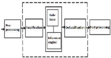
Fig.8.Fuzzy logic controller
The FLC contains three parts: Interference engine, Fuzzification, and Defuzzification. The FLC is characterized as, i.seven fuzzy sets for each input and output, ii.Triangular membership functions for simplicity, iii. Fuzzification using continuous universe of discourse, iv. Implication using mamdani ‗min‘ operator, v. Defuzzification using the height method
TABLE I: Fuzzy Rules Change
in error
Error
NB NM NS Z PS PM PB
NB NB NB NB NB NM NS Z
NM NB NM NM NM NS Z PS
NS NB NM NS NS Z PS PM
Z NB NM NS Z PS PM PB
PS NM NS Z PS PM PM PB
PM NS Z PS PM PM PM PB
PB Z PS PM PM PB PB PB
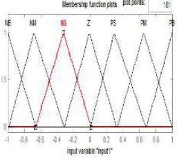
Fuzzification: Membership function values are assigned to the linguistic variables, using seven fuzzy subsets: NB (Negative Big), NS (Negative Small), NM (Negative Medium), ZE (Zero), PS (Positive Small), PM (Positive Medium), and PB (Positive Big). The Partition of fuzzy subsets and the shape of membership CE (k) E (k) function adapt the shape up to appropriate system. The value of input error and change in error are normalized by an input scaling factor.
In this system the input scaling factor has been designed such that input values are between -1 and +1. The triangular membership function of this arrangement presumes that for any particular E(k) input there is only one dominant fuzzy subset. The input error for the FLC is given as
E (k) = (4)
53
Copyright © 2016. Vandana Publications. All Rights Reserved.
Fig.9.Membership functions
Inference Method: Several configuration methods such as Max–Min and Max-Dot have been in the literature. In this paper Min method is used. The output membership function of each rule is given by the minimum operator and maximum operator. Table 1 shows rule base of the FLC.
Defuzzification : As a plant usually requires a non-fuzzy value of control, a defuzzification stage is needed. To compute the output of the FLC, „height‟ method is used and the FLC output modifies the control output. Further, the output of FLC controls the switch in the inverter. In active power, reactive power, terminal voltage of the line and capacitor voltage are required to be maintained. In order to control these parameters, they are sensed and compared with the reference values. To achieve this, the membership functions of FLC are: error, change in error and output .The set of FLC rules are derived from
u=-[α E + (1-α)*C] (6)
Where ‗α‘ is self-adjustable factor which can regulate the entire operation. ‗E‘ is the error of the system, C is the change in error and u is the control variable. A huge value of error ‗E‘ indicates the given system is in unbalanced state. When the system is in unbalanced state, the controller should increase its control variables to balance the system as early as possible. One the other hand, low value of the error ‗E‘ indicates that the system is near to balanced state.
V.
SIMULATION RESULTS
The 3-phase grid connected PV inverter is simulated in two different conditions. First, all PV panels are operated under the same irradiance S =1000W/m2 and temperature T =25 ◦C. At t
= 0.8 s, the solar irradiance on the first and second panels of phase a decreases to 600 W/m2, and that for the other panels stays the same. The dc-link voltages of phase a are shown in Fig.10.At the beginning, all PV panels are operated at an MPP voltage of 36.4V.
Fig: 10(a)
Fig: 10(b)
Fig: 10(a) DC-link voltages of phase ‗a‘ with distributed MPPT (T = 25 ◦C).
(a).DC-link voltage of modules 1 and 2 (b) DC-link voltage of module 3.
Fig: 11. PV currents of phase ‗a‘with distributed MPPT (T = 25 ◦C)
As the irradiance changes, the first and second dc-link voltages decrease and track the new MPP voltage of 36 V, while the third panel is still operated at 36.4 V. The PV current waveforms of phase ‗a‘ are shown in Fig. 11. After t = 0.8 s, the currents of the first and second PV panels are much smaller due to the low irradiance, and the lower ripple of the dc-link voltage can be found in Fig. 10(a).
Fig: 12 DC-link voltages of phase ‗b‘ with distributed MPPT (T=25◦C).
54
Copyright © 2016. Vandana Publications. All Rights Reserved.
controlled independently. In other words, the connected PV panel of each H-bridge can be operated at its own MPP voltage and will not be influenced by the panels connected to other H-bridges. Thus, more solar energy can be extracted, and the efficiency of the overall PV system will be increased.
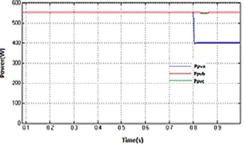
Fig: 13 Power extracted from PV panels with distributed MPPT.
Fig. 13 shows the power extracted from each phase. At the beginning, all panels are operated under irradiance S = 1000W/m2, and each phase is generate a maximum power of 555 W. After t = 0.8 s, the power harvested from phase a decreases to 400 W, and those from the other two phases stay the same. Obviously, the power supplied to the three-phase grid-connected inverter is unbalanced. However, by applying the modulation compensation scheme, the power injected to the grid is still balanced, as shown in Fig. 14. In addition, by comparing the total power extracted from the PV panels with the total power injected to the grid, it can be seen that there is no extra power loss caused by the modulation compensation scheme.
Fig. 14. Power injected to the grid with modulation compensation
Fig. 15. Three-phase inverter output voltage waveforms with modulation compensation
Fig. 15 shows the output voltages (vjN) of the three-phase inverter. Due to the injected zero sequence component, they are unbalanced after t = 0.8 s. The THD of the grid current is 0.57%.
Fig. 16. Three-phase grid current waveforms with modulation compensation
Fig: 16 THD Analysis
VI.
CONCLUSION
The multilevel inverter topology will help to improve the utilization of connected PV modules if the voltages of the separate dc links are controlled independently. Thus, a distributed MPPT control scheme for both single- and three-phase PV systems has been applied to increase the overall efficiency of PV systems. For the three-phase grid-connected PV system, PV mismatches may introduce unbalanced supplied power, resulting in unbalanced injected grid current. A modulation compensation scheme, which will not increase the complexity of the control system or cause extra power loss, is added to balance the grid current. A modular three-phase seven-level cascaded H-bridge inverter has been developed through simulation and verified with PV panels under different partial shading conditions. With the proposed control scheme, each PV module can be operated at its own MPP to maximize the solar energy extraction, FLC is used to reduce the THD value of grid current from 3.3% to 0.57% and the three-phase grid current is balanced even with the unbalanced supplied solar power.
REFERENCES
55
Copyright © 2016. Vandana Publications. All Rights Reserved.
[2] IEEE Standard for Interconnecting Distributed Resources WithElectic Power Systems, IEEE Std. 1547, 2003.
[3] 2002 National Electrical Code, Natl. Fire Protection Assoc., Inc., Quincy, MA, 2002.
[4] Characteristics of the Utility Interface for Photovoltaic (PV) Systems.CDV (Comittee Draft for Vote), IEC 61727, 2002. [5] J. M. Carrasco et al., ―Power-electronic systems for the grid integration ofrenewable energy sources: A survey,‖ IEEE Trans. Ind. Electron., vol. 53, no. 4, pp. 1002–1016, Jun. 2006.
[6] S. B. Kjaer, J. K. Pedersen, and F. Blaabjerg, ―A review of single-phase grid connected inverters for photovoltaic modules,‖ IEEE Trans. Ind. Appl., vol. 41, no. 5, pp. 1292–1306, Sep./Oct. 2005.
[7] M. Meinhardt and G. Cramer, ―Past, present and future of grid connected photovoltaic- and hybrid power- ystems,‖ in Proc. IEEE PES Summer Meet., 2000, vol. 2, pp. 1283–1288.
[8] M. Calais, J. Myrzik, T. Spooner, and V. G. Agelidis, ―Inverter for singlephase grid connected photovoltaic systems— An overview,‖ in Proc. IEEE PESC, 2002, vol. 2, pp. 1995–2000. [9] J.M. A.Myrzik andM. Calais, ―String and module integrated inverters for single-phase grid connected photovoltaic systems— A review,‖ in Proc. IEEE Bologna Power Tech Conf., 2003, vol. 2, pp. 1–8.
[10] F. Schimpf and L. Norum, ―Grid connected converters for photovoltaic, state of the art, ideas for improvement of transformerless inverters,‖ in Proc. NORPIE, Espoo, Finland, Jun. 2008, pp. 1–6.
[11] L. M. Tolbert and F. Z. Peng, ―Multilevel converters as a utility interface for renewable energy systems,‖ in Proc. IEEE Power Eng. Soc. Summer Meet., Seattle, WA, USA, Jul. 2000, pp. 1271–1274.
[12] H. Ertl, J. Kolar, and F. Zach, ―A novel multicell DC–AC converter for applications in renewable energy systems,‖ IEEE Trans. Ind. Electron., vol. 49, no. 5, pp. 1048–1057, Oct. 2002. [13] S. Daher, J. Schmid, and F. L. M. Antunes, Multilevel inverter topologies for stand-alone PV systems,‖ IEEE Trans. Ind. Electron., vol. 55, no. 7,pp. 2703–2712, Jul. 2008.
[14] E. Roman, R. Alonso, P. Ibanez, S. Elorduizapatarietxe, and D. Goitia, ―Intelligent PV module for grid-connected PV systems,‖ IEEE Trans. Ind. Electron., vol. 53, no. 4, pp. 1066– 1073, Jun. 2006.
[15] F. Filho, Y. Cao, and L. M. Tolbert, ―11-level cascaded H-bridge gridtied inverter interface with solar panels,‖ in Proc. IEEE APEC Expo., Feb. 2010, pp. 968–972.
[16] C. D. Townsend, T. J. Summers, and R. E. Betz, ―Control and modulation scheme for a cascaded H-bridge multi-level converter in large scale photovoltaic systems,‖ in Proc. IEEE ECCE, Sep. 2012, pp. 3707–3714.
[17] B. Xiao, L. Hang, and L. M. Tolbert, ―Control of three-phase cascaded voltage source inverter for grid-connected photovoltaic systems,‖ in Proc. IEEE APEC Expo., Mar. 2013, pp. 291–296. [18] Y. Zhou, L. Liu, and H. Li, ―A high-performance photovoltaic moduleintegrated converter (MIC) based on cascaded quasi-Z-source inverters (qZSI) using eGaN FETs,‖ IEEE Trans. Power Electron., vol. 28, no. 6,pp. 2727–2738, Jun. 2013.