_____________________________________________________________________________________________________ *Corresponding author: Email: [email protected];
Adaptive Design and Performance Evaluation of
Compact Acoustic Enclosures Built with GFRP for
Portable Mini-generators
Cornelius Ogbodo Anayo Agbo
1*1Department of Mechanical Engineering, University of Nigeria, Nsukka, Nigeria.
Author’s contribution
The sole author designed, analysed, interpreted and prepared the manuscript.
Article Information
DOI: 10.9734/JERR/2019/v7i316972 Editor(s): (1) Dr. Djordje Cica, Associate Professor, Faculty of Mechanical Engineering, University of Banja Luka, Bosnia and Herzegovina.
Reviewers: (1) Şükrü Kitiş, Dumlupınar University, Turkey. (2) Subrata Kumar Mandal, CSIR-Central Mechanical Engineering Research Institute, India.
(3) Yash Pal, Hindustan Institute of Technology and Science, India. Complete Peer review History: http://www.sdiarticle4.com/review-history/51956
Received 09 August 2019 Accepted 11 October 2019 Published 16 October 2019
ABSTRACT
A simple, portable and effective design for enclosing portable generators to reduce the radiated noise has remained a daunting challenge to noise control advocates in many developing countries. This research aims to use an adaptive design approach to create an enclosure for minimizing portable mini-generator noise. The noise characteristics of the mini-generators was ascertained and construction of a 730 by 640 by 600 mm enclosure was accomplished by using glass fiber reinforced plastic (GFRP) to build a double walled enclosure surfacing and rock wool as the sandwiched absorbing material. The sound pressure level (SPL) around the generator before and after the application of the enclosure was measured and evaluated. The results obtained showed that the acoustic enclosure could achieve an insertion loss of up to 16 dB (A) at a distance of 1.0 m. Also, the heat transfer characteristic of the enclosure design was put into consideration as well as the requirements of the engine air aspiration and cooling inside of the enclosure. Incorporation of fans in the acoustic enclosure design increased convectional fresh air circulation into, and discharge of the heat generated in, the enclosure, thus maintaining a safe temperature of about 40oC inside of the acoustic enclosure at the generator operating maximum load.
Keywords: Compact acoustic enclosure; portable mini-generator noise; sound pressure level; glass fiber reinforced plastic; insertion loss.
1. INTRODUCTION
A large number of individuals are exposed to noise hazards on daily basis without consideration. Noise can cause physical problems such as permanent hearing loss, as well as psychological traumas, stress, annoyance and communication distortions. In many developed countries more and more requirements by regulating bodies are being applied to every facet of daily life in order to reduce noise pollution. Cars have limiting noise requirements, new buildings have code requirements on the amount of transmitted noise through its walls [1,2]. With the frequent power outages in many developing countries, the use of portable generators is increasing. Even though these items of convenience are beneficial to us, they are extremely loud during operation. Mini generators constitute part of the noise sources within the neighbourhoods and communities in the developing economies with little limiting noise regulation.
There are two general methods which can be used to achieve the required noise levels; active and passive noise control. Active noise control (ANC) involves generating a stable destructive interference pattern of noise against a transmitting noise. It is specific in its application. It works well for the control of low frequency noise sources [3]. ANC requires state-of-the-art electronic hardware and precise computer software. It is an expensive form of noise control often requiring large amounts of engineering time and costly control systems. The active noise control can however be used to complement the passive control where necessary [4].
The most cost effective and widely used form of noise suppression is the passive noise control. Passive control is achieved by the use of barriers, enclosures or some type of acoustical material. Barriers are large panels that interrupt the direct “line of sight” from the noise source to the receiver. Technically, the barrier acts as a reflective surface. The noise is reflected off of the surface and back at the source. Barriers are effective when the noise source or the receiver is too big to enclose in a structure. When the noise source is small enough to permit the construction of barriers on all sides of the source, the barrier effectively becomes an enclosure. Sound reflection occurs when the acoustic wave is
reflected back towards the source by the material. A material with significantly greater impedance than the surrounding medium, in which the acoustic wave travels, will cause reflection. Hence no noise will pass through such an enclosure material. In order for a material to have sound reflecting properties that will provide effective noise attenuation in most settings, the material must be very dense, and very thick. This results in a massive, heavy enclosure construction.
For a lighter weight portable enclosure, noise attenuation is achieved by the use of an acoustic absorbing material. An absorbing material is used in this context to describe the material’s ability to attenuate or absorb the sound’s incident pressure wave, thus reducing the amplitude of the transmitted and reflected pressure waves. The resulting sound pressure level on the opposite side of the absorbing material will therefore be reduced.
The purpose of this research is to design and evaluate the performance of a functional and practical enclosure. The portable enclosure will attenuate some of the radiated sound due to the absorbing mass of the structure, and its effectiveness will depend on the source to panel distance, and also the stiffness of the enclosure material, the enclosure panel vibration and the panel thickness. The optimal design of the enclosure will be guided by specific material properties and panel thickness depending on the sound pressure level noise spectrum.
The enclosure is developed to reduce the sound pressure level of commercial portable mini electricity generators. It focuses on the selection of the appropriate primary material for the construction and the geometry of the enclosure. Enclosures are ideally, sealed environments and any opening or gap in the enclosure allows sound to escape uninterrupted which is detrimental to the function of the enclosure. Although, it is practically impossible to have a completely sealed design as allowances are made for cooling fans, piping for exhaust gas and wiring for the output socket and switch.
radiated noise of the generator, the research defines precise design methods intended to optimize the performance of a passive enclosure for a generator. The primary focus will be on the insertion loss of the enclosure, cooling and heat transfer requirements and minimal cost through material selection and fabrication technique. The enclosure is intended to be fabricated from commercially available materials.
2. LITERATURE REVIEW
The identification of noise source and its characteristics is a first step in the study of noise mitigation measure. Krishna and Wegrzyn [5] surveyed noise suppression technologies and a background review of diesel engine noise and observed sources of noise to include engine airflow interactions, combustion noise and mechanical noise. They attributed the combustion noise to the rate of change in gas pressure due to combustion and therefore dependent on the type of injection and combustion system. The mechanical noises arise from the valves, gear train, etceteras. Jozwik [6] also presented an analysis of sound field emitted by selected CNC machine tools which enable the isolation of the noise from the workers. The identification of the noise sources and level measurements at different bandwidths of frequency enables proper designs and selection of appropriate materials. In a noise suppression review in package generators, Okpighe [7] surmised that the economics, environment of usage, mobility and versatility of the package generator suggests that passive control method for noise should be considered as the first line of action. The design, testing and installation of the noise suppression unit are a welcome development. With the improvement, the efficiency and effectiveness of the package generator will be enhanced and this will elevate the overall health and wellbeing of the society.
In a passive control the amount of transmission or insertion loss that the enclosure panel will provide is primarily dependent on the internal damping of the panel material. To increase transmission loss, a double walled system is implemented. This type of configuration has two panels separated by a gap. The gap is usually filled with a sound absorbing material to further enhance the transmission loss. Kinsler and Frey [8] stated that the transmission loss of a double panel system where the acoustic impedance surrounding both panels is the same is simply the transmission loss of one panel plus the
transmission loss of the second panel. However, a double partition does not always increase the sound transmission loss at every frequency. The double partition may be less effective than each of the single partitions individually at low frequencies because then the double partition acts as if it were a single degree-of-freedom resonator system. The double layer partition becomes an effective mass-spring-mass system and the result is extremely deleterious at low frequencies [9]. This effect was especially prevalent for small gap distances between panels, such as those found in close fitting enclosures. These discussions of double walled enclosures also assume no mechanical coupling between the two panels which is an ideal situation and cannot be fully realized in practice. Unlike insertion loss, transmission loss measurement is difficult to obtain as it focuses on the pressure wave immediately before and immediately after the panel surface which is assumed to be completely rigid. The near field effect of the noise source on the enclosure panel forces the panel to vibrate thereby making the panel surface behave as a non-rigid wall which is subject to many modes of vibration. It is therefore more beneficial and practicable to evaluate the enclosure or barrier from the perspective of insertion loss. Insertion loss is the reduction in SPL of a noise source. It is more effective, and measurable, than the transmission loss of an enclosure. To measure insertion loss, an array of microphone positions is used around a piece of machinery or equipment [10,11,12].
Insertion loss is similar to transmission loss with respect to material thickness, density and stiffness. The denser and thicker the panels of the enclosure are, the more transmission loss there will be in the mass controlled region. For low frequencies, the greater the stiffness the more insertion loss there will be in the stiffness controlled region [13,14,15].
Sound pressure level measurements are taken with the equipment operating. The enclosure is then applied and the same sound pressure level measurements are taken again. There is no need to get measurements of incident and transmitted pressures. As long as the measurements are taken in the same locations and the background noise is taken into account, insertion loss measurements are rather simple.
noise source to panel dimension is less than 1.0 meter. The acoustical field inside the close fitting enclosure does not behave the way it would in a large room as there is normally considerable coupling between the noise source and the enclosure [16]. There are numerous other considerations in enclosure design beyond noise levels, such as airflow, exhaust, site requirements and weather protection [17]. The design, materials used and the construction of the enclosure should be such as to minimize additional weight and be able to withstand ambient temperatures between -50ºF (-46ºC) to +140ºF (+60ºC) at any possible humidity [5]. The design and construction should also be easily transportable for such a portable generator, permit quick setup and sufficiently rugged. The design should be such as to minimize maintenance and possess mean time between overhaul at least equal to that of the engine – generator system. Parvathi and Gopalakrishnan [18] studied control of noise from portable power generator through experimental assessment and mitigation of indoor and near-field noise levels due to the generator operation using anti-vibration mounts and various configurations of enclosure panels. Tandon et al. [19] identified the major sources of noise in a petrol-start kerosene-run portable internal combustion engine driven generator-set and treated them in parts. To suppress the noise and avoid the cooling problem associated with full enclosures, a partial enclosure, constrained layer damping treatment and stiffening of the cooling fan cover, and rigid clamping of the silencer were applied to reduce the noise. It was however noted that for an insertion loss of more than 10 dB a full enclosure is required.
According to Bloxsom [20] acoustic insulation sound-absorbing acoustic foam is effective for controlling high frequency noise and is used extensively in outdoor enclosures. In indoor installations, it can be very effective at reducing noise when used to line air ducts or when used as wall or ceiling covering. The use of fire retardant urethane foam and fiber glass as the absorbing material for enclosures is recommended [21]. Kuku et al. [22] developed a sound proof enclosure for portable generators fabricated from plywood panels, a combination of sawdust and grinded glass with perforated foam inner lining were used as absorbers. Mushiri et al. [23] proposed using the same plywood, combination of sawdust and grinded glass and polyurethane foam, but added a heat exchanger for transferring out the heat built up inside the
enclosure. Akhaze and John [24] also developed a sound proof enclosure for a 950 W rated portable generator using medium density fireboard lined with polyurethane foam. Hammad et al. [25] discussed on materials selection of adequate noise suppressant suitable for generator canopy as well as effective heat transfer technique to ensure stable generator function. They evaluated concrete, brick, steel, aluminium, wood and plywood, and settled for steel panels and rock wool absorber combination as preferred choice. Karuppiah and Ramiah [26] carried out an assessment for possible use of jute fiber, which is a cheaper and biodegradable natural fibre material, as alternative soundproofing replacement for synthetic materials like gypsum and foam. While the result is promising, it is worthy of note that natural fiber materials are susceptible to moisture absorption, pests and fungi attacks and subsequent deterioration. Generally, most materials that are efficient at sound absorption are usually soft and fluffy with many air spaces to trap sound waves and weaken them after several reflections inside them. From the literature assessment, it is observed that glass fiber reinforced polymer composite panels have not been tried in the construction of acoustic enclosure for mini generators. It is therefore a mission to develop passive acoustic enclosure to suppress the noise emitted by mini generators using glass fiber reinforced polymer composite panels with rock wool sandwich absorber.
3. METHODOLOGY
Design considerations: Some major design considerations were made during the fabrication of the enclosure and these include; the type and level of noise produced by the targeted categories of generators, heat generation and control within the enclosure, the sizing of the enclosure and materials selection. A typical model of the discussed generators is shown in Fig. 1a. It is a petrol engine run generator with rated output of 450 W at 50 Hz frequency.
(a) (b)
Fig. 1 (a) A typical portable petrol engine run mini-generator and (b) Sound level meter
Heat control and exhaust emission removal: forced convection was adopted using fans to draw-in fresh air and expel exhaust gas which would have otherwise lowered the engine combustion efficiency.
The overall dimension of the generator was taken into consideration in providing a suitable cross-sectional dimension of the acoustic enclosure. Because the generator noise SPL is more in the low frequency region, to avoid acoustic resonances caused by standing wave between the enclosure panel and the generator, the space in-between was limited but enough to enable air movement and easy removal of the generator from the enclosure. The standing wave frequency, f, is given by [8].
= /2
where c = 20.05√T = speed of sound (ms-1); T = temperature (313 K) and d = distance between source (generator) and panel. A maximum distance of 0.10 m between the generator and the side panel gave 1774 Hz which is high and outside the low frequencies of the generator noise but within the high frequency region. A sandwiched rock wool with perforated inner casing was adopted to destroy the standing wave
by absorption, reduction of the noise amplitude and raising the frequency of the wave.
Materials: As a way to achieve the goal of generator noise reduction using the passive noise control method, which is cheaper to implement and widely used, the following materials and tools were deployed.
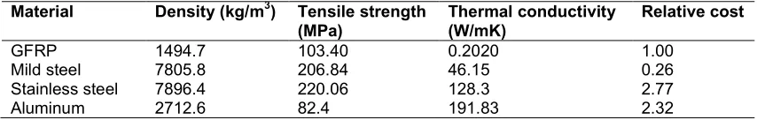
Glass fibre reinforced plastic (GFRP): the choice of glass fiber reinforced composite laminate was informed by its excellent strength to weight ratio (see Table 1), high natural damping ratio, high durability, high insulation, corrosion free and water proofing property.
GFRP was produced from procured E-glass fibre mats (with area density of 450 g/m2) which serve as the reinforcement and unsaturated polyester resin which serves as the binding matrix; methyl ethyl ketone peroxide (MEKP) catalyst and cobalt naphthanate accelerator which acted as curing agents.
Rockwool absorber material: The vast majority of rock wool use in the world is used for insulation purposes much like fiberglass. Rock wool was used as absorbent and incorporated in-between the interior and exterior casing. The acoustical
Table 1. Desired properties comparison of glass fibre reinforced plastic [27]
Material Density (kg/m3) Tensile strength (MPa)
Thermal conductivity (W/mK)
Relative cost
GFRP 1494.7 103.40 0.2020 1.00
Mild steel 7805.8 206.84 46.15 0.26
Stainless steel 7896.4 220.06 128.3 2.77
Table 2. Sound absorption Properties of Rockwool, oil palm fibre, and coir fibre [29]
Sound frequency (Hz)
Sound absorption coefficient Rock wool Oil palm
fibre
Coconut coir fibre
Polyurethane foam 5 cm
Fibrous glass 5cm
Wood
125 0.54 0.20 0.19 0.35 0.2 0.15
250 0.74 0.30 0.21 0.51 0.55 0.11
500 0.93 0.61 0.44 0.82 0.89 0.10
1000 0.95 0.91 0.64 0.98 0.97 0.07
2000 0.95 0.81 0.74 0.97 0.83 0.06
4000 0.95 0.96 0.76 0.95 0.79 0.07
behavior of a rock wool product depends mostly on the following properties and characteristics: airflow resistance, dynamic stiffness, surface protection of the product, density (kg/m3), fibre diameter and fibre orientation. The absorption of energy from a sound wave mainly depends on the airflow resistivity of the wool [28]. If the resistivity is too high, the sound wave is reflected and only a minor part is absorbed. If the resistivity is too low, the sound wave can pass through the wool without being absorbed. As shown in Table 2 both rock wool and fibre glass gave high absorption coefficients at frequency range of 125 Hz – 500 Hz. Thus a choice was made that satisfies the generator disturbing noise frequency range.
Fans: SUNON fans model DP200A with operating voltage of 185 – 245 VAC, rated speed 2850/3150 rpm, air delivery 97/117 CFM, static pressure 0.34/0.39 inch – water column, input power 22/21 W and noise level of 45/50 dB(A). The fans help to suck in fresh air and drive out heated air from inside of the enclosure based on their facings.
Sound level meter: V&A, VA8080 sound level meter designed according to the IEC651, Type 2 and, frequency weighting: A Type, used to measure the sound pressure level of the mini generator noise (see Fig. 1(b)).
Methods: Some engineering design optimization techniques were adopted in producing the enclosure. The conceptual design in 3-D AutoCAD drawings (see Fig. 2(a) and (b)) of the acoustic enclosure both in closed and open conditions is presented below. The acoustic enclosure is a double walled enclosure with rock wool placed in between them (see Fig. 3). Composite laminates of 3 mm thickness were produced from E-glass fiber and unsaturated polyester resin using the wet lay-up method [29]. The laminates were cut to sizes and cold welded to form the inner and the outer casing with
dimensions of 610 by 520 by 480 mm and 730 by 640 by 600 mm respectively. These measurements were adopted after considering the sizes of typical mini generators, with maximum overall dimensions of 590 by 500 by 470 mm for Yamaha and 375 by 315 by 325 mm for Tiger portable mini-generators.
The two boxes were such that they fit together with the outer box enveloping the inner one but with a gap of 60mm between them. The top panel was constructed to form the door through which the generator could be accessed. The internal wall was perforated with checkered holes to enhance the acoustic attenuation capabilities of the enclosure. The perforated panel and the air space acts like a resonator type muffler system [30]. The perforated panels have small diameter holes that are spaced far apart relative to the hole’s diameter. The double wall enclosure box was made by placing 60 mm rock wool inside the outer casing and then inserting the perforated inner casing and cold welding them with some trimming materials. Holes were created for the fans, socket installation and wirings.
The generator is also expected to generate heat in the enclosure which if not controlled, would reduce the efficiency of the generator. The heat transfer characteristics of the enclosure design were put into consideration as well as the requirements of the engine aspiration air and cooling inside of the enclosure. Three through holes of diameter 120 mm each were made at strategic positions on both sides of the enclosure box for the cooling fans installation.
enclosure using the sound level meter. The evaluation was carried out according to the ISO 8528-10 standard [31]. The background noise was 52 dB (A) during the tests.
The thermal condition of the generator was also monitored from start and readings taken of the temperature of the inside of the acoustic enclosure at time intervals while the generator was on full load. The inside enclosure ambient
temperature was obtained by inserting a thermocouple sensitive junction into the enclosure. Two sets of readings were obtained; first trial with the fans switched off and in a second trial with the fans switched on. Because the experiment was done outside during the morning hours, the temperature of the outside surrounding was rising with the sunrise and reached up to 32ºC by the end of the experiment.
(a)
(b)Fig. 2. Isometric views in 3-D AutoCAD design of the acoustic enclosure in (a) closed and (b) open conditions
Fig. 3. Enclosure panel composition: GFRP composite laminate and rock wool sandwich
3 mm FRP 60 mm rock
4. RESULTS AND DISCUSSION
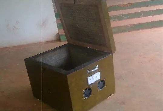
Fig. 4 shows the locally designed and fabricated acoustic enclosure for mini generators. The generator is displayed in an open condition in which the generator can be placed and then closed during operation. The total size of the portable acoustic enclosure in closed condition is 730 mm by 640 mm by 600 mm.
Fig. 5 shows the sound pressure levels (SPLs) of the generator noise for both with and without the acoustic enclosure. It can be seen that at a distance of 0.5 m the SPL of the generator noise dropped from 87 dB(A) without the enclosure to 74 dB(A) with the enclosure resulting in an insertion loss of 13 dB(A). This could be attributed to the blocking and damping of the high frequency noise by the composite panels as well as the absorption by the rock wool ma At 1.0 m the insertion loss increased to about 16 dB(A) and at 2.5 m the insertion loss increased up to 21 dB(A). The increase in insertion loss with distance away from the generator and enclosure seems to suggest that the near field source effect decreases as the distance away from the generator increases. Also the low frequency noise which is usually difficult to attenuate using passive control gets attenuated by the atmospheric air as distance from generator noise source increases.
The generator noise without the enclosure was deadened out at a distance of 64 m but with the enclosure the generator noise was not perceived at a distance of 21 m shortening the noise perception distance by more than 67%. It
Fig. 4. Locally designed and fabricated acoustic enclosure for mini generators 4. RESULTS AND DISCUSSION
4 shows the locally designed and fabricated acoustic enclosure for mini generators. The generator is displayed in an open condition in which the generator can be placed and then closed during operation. The total size of the closed condition is
Fig. 5 shows the sound pressure levels (SPLs) of the generator noise for both with and without the acoustic enclosure. It can be seen that at a distance of 0.5 m the SPL of the generator noise 87 dB(A) without the enclosure to 74 dB(A) with the enclosure resulting in an insertion loss of 13 dB(A). This could be attributed to the blocking and damping of the high frequency noise by the composite panels as well as the absorption by the rock wool material. At 1.0 m the insertion loss increased to about 16 dB(A) and at 2.5 m the insertion loss increased up to 21 dB(A). The increase in insertion loss with distance away from the generator and enclosure seems to suggest that the near field decreases as the distance away from the generator increases. Also the low frequency noise which is usually difficult to attenuate using passive control gets attenuated by the atmospheric air as distance from
noise without the enclosure was deadened out at a distance of 64 m but with the enclosure the generator noise was not perceived at a distance of 21 m shortening the noise perception distance by more than 67%. It
appears to be that the weak noise waves tha were transmitted through the enclosure wall or escaped through provisional openings to the outside of the enclosure were rapidly dampened out by the atmospheric air. Hence with the acoustic enclosure the generator could be located closer to the use envir
shorter cable, with more efficient power transfer and better monitoring.
In order to evaluate the fans cooling effect on temperature inside the enclosure the temperatures without and with the fans on were measured and compared. Table 3 and
show the temperature measurements inside the enclosure without the fan on and with the fan on respectively while the generator was in operation. It was observed that without the fan the temperature inside the acoustic enclosure rose to 110ºC within 40 minutes which is above the recommended safe limit of 65ºC. This portends a danger to the generators service life as heat accumulates inside the enclosure. However with the fans on the maximum temperature attained was 40ºC. This suggests that the fans effectively and continuously expelled out the heated air inside the enclosure as it is been generated while drawing in fresh air for the effective generator functioning.
Table 5 shows the values for temperature measurement with time in the surrounding environment due to the daily sunrise during the experimental test. The temperature of the environment increased by about 3°C within the 80 minutes monitoring from about 12.00 noon to 1.20 pm.
Locally designed and fabricated acoustic enclosure for mini generators
appears to be that the weak noise waves that were transmitted through the enclosure wall or escaped through provisional openings to the outside of the enclosure were rapidly dampened out by the atmospheric air. Hence with the acoustic enclosure the generator could be located closer to the use environment with shorter cable, with more efficient power transfer
In order to evaluate the fans cooling effect on temperature inside the enclosure the temperatures without and with the fans on were measured and compared. Table 3 and Table 4 show the temperature measurements inside the enclosure without the fan on and with the fan on respectively while the generator was in operation. It was observed that without the fan the temperature inside the acoustic enclosure 40 minutes which is above the recommended safe limit of 65ºC. This portends a danger to the generators service life as heat accumulates inside the enclosure. However with the fans on the maximum temperature attained was 40ºC. This suggests ffectively and continuously expelled out the heated air inside the enclosure as it is been generated while drawing in fresh air for the effective generator functioning.
Table 5 shows the values for temperature measurement with time in the surrounding ronment due to the daily sunrise during the experimental test. The temperature of the environment increased by about 3°C within the 80 minutes monitoring from about 12.00 noon to
Fig. 5. Generator noise sound pressure level (SPL) measurements for both with and without the acoustic enclosure
Table 3. Temperature measurement inside the model enclosure without cooling fans
Temperature (°C) 29 38 54 65 78 86 91 94 100 105 110
Time (min) 0 2 6 10 14 18 22 26 30 34 40
Table 4. Temperature measurement inside the enclosure with cooling fans
Temperature (°C) 29 32 35 37 40 40 40
Time (min) 0 5 10 15 20 25 30
Table 5. Temperature measurement of the surroundings due to sunrise outside the enclosure
Temperature (°C) 29 29 30 31 32 32
Time (min) 0 10 20 40 60 80
The enclosure was equipped with lifting handles to facilitate its movement as both the generator and the acoustic enclosure are expected to be frequently taken from one place to another as need arises. The total weight is about 20 kg which is light enough for such a portable design and without necessarily compromising the noise reduction capability.
5. CONCLUSION
An acoustic enclosure for mini generators have been designed and fabricated to help reduce the noise pollution in communities and neighbourhoods. The need to get rid of unwanted sound or reduce noise pollution cannot be over emphasized. The combination of fibre reinforced plastic surfacing and rock wool absorbent sandwich made the enclosure light, portable and suitable for mini generator noise attenuation. The passive noise control method used in the
enclosure was effective in reducing the sound pressure level by 16 dB (A) at 1m distance and 21 dB(A) at 2.5 m distance, which is an indicator of the high performance of the enclosure in sound reduction. It was observed that the generator noise without the enclosure was perceived up to a distance of about 64m but when placed inside the acoustic enclosure the sound was not heard at a distance of about 21m away from the enclosure. Hence locating the enclosed generator at about one third of the no enclosure deadened sound distance will give the same result. With the help of the cooling fans the temperature of the enclosure was maintained at a temperature of about 40°C, which is safe for the generator operation. Though the result of the model would improve for a completely sealed enclosure but this is not practicable due to the need to provide for the generator cooling and effective engine operation. The exhaust system emissions, both noise and carbon monoxide,
0 10 20 30 40 50 60 70 80 90 100
0 0.5 1 1.5 2 2.5 3
SP
L
(d
B
A
)
distance from generator (m)
SPL (dB A) without enclosure
pose significant challenge in the design of an effective enclosure. A further study is required to determine the contribution of the exhaust noise to the overall radiated sound pressure level to enable a combined design to handle the noise as well as the fumes.
ACKNOWLEDGEMENTS
I wish to acknowledge the contributions of my undergraduate supervisees and the JuNeng Nig. towards the execution of the project.
COMPETING INTERESTS
Author has declared that no competing interests exist.
REFERENCES
1. Oserogho & Associates. The law, the environment and permissible noise levels. Business Regulations, Law & practice environment, Proshare Economy; 2017. 2. Environmental Protection Authority.
Regulatory impact statement: proposed environmental protection (residential noise) regulation 2018, Victoria, Australia; 2018. 3. M. Saif, Abd El Gawad, Acoustical
treatment of emergency power generator, 14th International Congress on Sound & Vibration (ICSV14) Cairns. Australia; 2017. 4. Cuesta M, Cobo P. Optimisation of an active control system to reduce the exhaust noise radiated by a small generator. Appl Acoust. 2001;62:513– 526.
5. Krishna CR, Wegrzyn JE. Survey of noise suppression systems for engine generator sets. Brookhaven National laboratory (BNL) 67163 Informal Report; 1999. 6. Jozwik J. Identification and monitoring of
noise sources of CNC machine tools by acoustic holography methods. Advances Sci Technology Research J. 2016;10(30): 127–137.
7. Okpighe SO. Review of noise suppression in package generators. J Sci Research & Reports. 2015;5(5):361–374.
8. Kinsler LE, Frey AR. Fundamentals of acoustics, John Wiley and Sons, New York; 1982.
9. Vinokur RY. Evaluating sound transmission effect in multi-layer partitions, J. Sound Vib; 1996.
10. Ghorbani Z, Hassan-Beygi SR, Ghobadian B. Noise reduction of a portable gas
generator set using an acoustic enclosure, Agricultural Engineering International: CIGR J. 2016;18:(3):159–170.
11. Paillasseur S, Chaufour ., Measurement of component’s sound power emission on PSA’s diesel engine by means of 3D acoustic imaging technique and its applications. In 22eme Congres Francaise de Mecanique, Lyon, 24 au28 Aout; 2015. 12. ISO 1996 – 2 International Standard 2nd
ed.: Acoustics- Description, measurement and assessment of environmental noise – Part 2: Determination of environmental noise levels; 2007.
13. O’Boy DJ, Krylovk VV. Vibration of a rectangular plate with a central power-law profiled groove by the Rayleigh – Ritz method. Appl Acoust. 2016;104:24–32. 14. Bowyer EP, Krylov VV. Experimental
investigation of damping flexural vibrations in glass fibre composite plates containing one – and two – dimensional acoustic black holes. Composite Structures. 2014; 107:406 – 415.
15. Hawkings TG. Studies and research regarding sound reduction materials with the purpose of reducing sound pollution. M.Sc. California Polytechnic State University; 2014.
16. Oldham DJ, Hilarby SN. The acoustical performance of small close fitting enclosures, Part 2, experimental investigations. J Sound and Vib. 1991; 150:283-300.
17. Gries D. Noise control solutions for standby power generators. EAR Aearo Technologies LLC, Indianapolis, Indiana; 2004.
18. Parvathi K, Gopalakrishnan AN. Studies on control of noise from portable power generator, In Proceedings of the Third International Conference on Environment and Health, Chennai, India; 2003;328– 338.
19. Tandon N, Nakra BC, Ubhe DR, Killa NK. Noise control of engine driven portable generator set, Appl acoust. 1998;55(4): 307–328.
20. Bloxsom W. Sound science: understanding and implementing generator set noise control. MTU Onsite Energy; 2013.
21. Genesis – Soundproofing and Generators; 2015.
Available:acoustics.co.za
Research J Appl Sci, Eng Technology. 2012;4(16):2600–2603.
23. Mushiri T, Madziro N, Mbohwa C. Design of an optimum acoustic enclosure for an open frame diesel generator. 14th Global conference on Sustainable Manufacturing, GCSM 3 – 5 October 2016, Stellenbosch, south Africa, Procedia Manufacturing. 2017;8:424–431.
24. Akhaze MN, John E. Development of a soundproof device for 950 Watt rated portable generators, J Appl Sci Environmental Management. 2016;20(1): 83–86.
25. Hammad U, Aizaz A, Kahn A, Qurehi T, Design and development of noise suppression system for domestic generators, Special edition. European Sci J; 2013.
26. Karuppiah T, Ramiah KVS. Testing various synthetic and natural fiber materials for soundproofing, J Emerging Investigators; 2017.
27. Rockwool Marine and Offshore Acoustic Manual, 3rd edition, Denmark; 2010. 28. Maa DY, Microperforated-panel wide band
absorbers. Noise Control Engineering J. 1987;29(3):77-85.
29. Wood R. Car bodywork in glass reinforced plastics, plymouth, London: Pentech Press; 1980.
30. Dept of Occupational Safety and Health, Malaysia: Guidelines for control of occupational noise; 2005.
31. Marazza C. Noise and vibrations measurements and analysis in high power diesel generating sets, M. Engineering Project, Politecnico Milano; 2016.
© 2019 Agbo; This is an Open Access article distributed under the terms of the Creative Commons Attribution License (http://creativecommons.org/licenses/by/4.0), which permits unrestricted use, distribution, and reproduction in any medium, provided the original work is properly cited.
Peer-review history:
![Table 2. Sound absorption Properties of Rockwool, oil palm fibre, and coir fibre [29]](https://thumb-us.123doks.com/thumbv2/123dok_us/9830780.1969215/6.612.97.518.116.216/table-sound-absorption-properties-rockwool-palm-fibre-fibre.webp)