INTRODUCTION
Software systems are extremely complex; the amount of information contained in a system implementation is more than we can hope to comprehend. The same is true of the natural world that surrounds us, and we cope with it in exactly the same way: by creating a suitable model of the system, and working with that.
The suitability of a model depends upon the intended application. Clearly, we must include every piece of information that is relevant to our purpose, but we must also try to exclude any piece of information that is not. A model with too much information may be difficult to comprehend, and too complex for automated software engineering.
A model that is entirely suitable for one purpose may be less suitable for another: some vital piece of information may be missing. If we have several purposes in mind, then we may need several different models of the same system. A sensible, economical way of doing this is to define a single large model of the system, and then construct smaller models as projections of this model, one for each purpose.
Using UML for automatic test generation
Y. PRASANTH, K. SUBBA RAO and L.S.S. REDDY
K.L. College of Engineering, Vaddeswaram, Guntur District (India).
(Received: October 10, 2008; Accepted: November 21, 2008)
ABSTRACT
This paper presents an architecture for model-based verification and testing using a profile of the Unified Modeling Language (UML). Class, object, and state diagrams are used to define essential models: descriptions that are relatively complete. Object and state diagrams are used to introduce test directives. Models written in this profile may be compiled into a tool language: the Intermediate Format (IF). Descriptions written in IF can be animated, verified, and used to generate tests. As well as defining the profile for UML, the paper explains the basis of the compilation into IF, and reports upon the problems encountered.
Key words: UML, automatic test generation.
In this paper, we describe an architecture for model-based verification and testing in which projected models are generated automatically for each specified purpose. We explain how these projected models can be translated-again, automatically-into a language of state machines, animated, verified, and used as a basis for automatic test generation. The models and purposes are described using the United Modeling Language (UML)10, although the architecture could
be applied to any modeling language with as suitable, state-machine semantics.
We begin with a descr iption of the architecture itself. In Section 3, we define a UML profile for models and purposes. In Sections 4 and 5, we explain how models are translated into eXtensible Meta-Language (XML), projected, and then compiled into the Intermediate Format (IF). We end with a discussion of related and future work.
Architecture
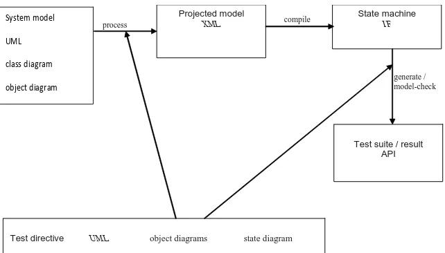
The first component of the architecture is the system model, written in UML; this is a collection of class, state, and object diagrams:
• The state diagrams-one for each class-explain how these entities may evolve. ´ The object diagram specifies an initial
configuration.
The object diagram is not required if an initial configuration is supplied for each test.
The second component, again written in UML, is the test directive; this consists of object and state diagrams:
´ The object diagrams informs the construction of the projected model, identifying particular states of interest;
´ The state diagram explains how the projected model is to be explored.
The system model and the test directive can be constructed using any of the standard toolsets, such as Rational Rose³ or Together Control Center16. The model is then exported in XML
Metadata Interchange (XMI)9 format, and processed
to produce a projected version. The processor takes, as an additional input, the object diagrams from the test directive, again in XMI format.
The projected version of the model is written in XML, using a set of schemas in which the information needed for the subsequent compilation is easily accessible. Naturally, the compiler could be written to accept XMI, but
´ separating the tasks of orientation and compilation simplifies the design of the compiler;
´ it is easy to define-and embed-extensible Style-sheet
Language (XSL) transformations between XMI and our compiler-oriented XML representation. The compiler takes the XML representation of the projected model and produces a collection of interacting state machines, written in the Intermediate Format (IF) language¹. The form of each machine is dictated by the state diagrams of the projected model, their interaction mimics the action–event mechanism of UML.
An if representation can be animated, verified, or model checked using the tools of the CAESAR/ALDEBARAN Development Package (CADP)6. In this case, the test directive describes a
test upon the model, a property to be checked, and the output is either a confirmation that the property holds, or an explanation of why it does not. Alternatively, an IF representation can be provided as input to the TGV (Test Generation with Verification) tool7.
In this case, the state diagram component of the test directive is used to guide the exploration of the underlying transition system, constructed-on-the-fly, if necessary-from the IF state machine description.
System model
UML
class diagram
object diagram
process compile
generate / model-check
Projected model
XML State machineIF
Test directive UML object diagrams state diagram
Test suite / result API
TGV provides output in Tree and Tabular Combined Notation (TTCN)-a standard format in the telecommunications industry-but this output can be translated to produce test cases in the language of any API (Applications Programming Interface), whether this is C, C++, or Java.
Using UML
The Unified Modeling Language (UML)10
is a set of techniques for specification, visualisation, and documentation. The language is based primarily upon object-oriented methodology; however, concepts were added from Harel’s language of StateCharts¹¹, Petri Nets, Message Sequence Charts and SDL.
An impor tant aspect of UML is the presence of variation points in the language semantics: the definition of the language is intentionally incomplete; further interpretation is required before a model written in UML can be used as a basis for formal analysis or automatic test generation.
Also required is instantiation. UML does not include a language of data types and operations; instead, these are written in the target language of the specification, nor mally an imperative programming language. If we wish to compile our models, we must define a target language.
The selection of a target language, and a prescription that lists the various notations and features-UML comprises several different notations, each with a range of features-is called a UML profile. In this section, we will describe a UML profile for system models and test directives.
Target language
We will use IF as our target language. Operations, actions, and data types will all be written using a basic subset of IF syntax, accessible to anyone who has some familiarity with imperative programming languages. There are two obvious advantages to this choice:
´ our diagrams will use the same target language, whether the language of implementation is C, C++, or Java;
´ The compiler can focus upon the translation
of state machines, and the interpretation of UML actions; it does not need to translate primitives.
The translation from the implementation language of an API-whether it is C, C++, or Java-to this syntax is easily automated. The only aspect that invites user intervention is the choice of data representation.
The primitive types defined for IF include the standard C datatypes, float, arrays, and records. So user intervention is not required; however, it may be desirable. If we choose abstract interpretations for our model, using user defined enumerations, our projected models will be smaller, and more amenable to analysis.
Class diagrams
A class is a description of a set of objects that share the same attr ibutes, operations, relationships, and semantics. In a class diagram, each class is drawn as a rectangle with three compartments: the top compartment holds the class name, the middle holds a list of attributes; the bottom holds a list of operations.
In our profile, attributes may be observable: the values of observable attributes may be inspected at any point during a test. By default, attributes are not observable: we indicate that they are by adding a tag.
Operations may also be observable, in that the occurrence of the operation (and any return value) will be recorded in any projected model. Furthermore, they may be controllable, indicating that they may be called from outside the system during a test; we may use another tag to indicate this.
Object diagrams
An object diagram shows the state of the system at a certain point in time, as a collection of objects, each in a particular state. We will use object diagrams to describe the initial configuration of the system model, to specify a starting configuration in a test directive, and to flag configurations for inclusion or exclusion in a projected model.
The object diagram notation is similar to the class notation, although there are now only two compartments to each rectangle. The state of an object may be constrained using an assertion, a state name from the corresponding state diagram see below, or by constraining the values of its attributes.
The presence of a link between objects indicates that communication is possible:
• call actions in one object can produce call events in the other;
• send actions in one object can produce signal events in the other.
A link may be decorated with information about roles: an attribute name at one end of a link reveals the name used, within the context of the closer object, for the object at the other end.
The role of the object diagram itself is indicated using a stereotype:
• <<initial>>: the initial state of the system model; • <<start>>: the start state of the projected model; • <<finish>>: a finish state for testing;
• <<include>>: a state to be included in tests; • <<exclude>>: a state to be excluded.
State diagrams
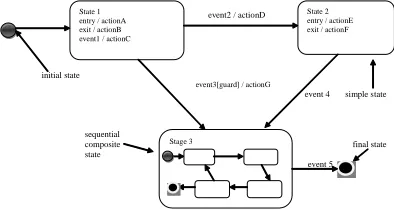
A state diagram shows how an object will react to the arrival of an event. Each reaction may be a sequence of actions, possibly accompanied by a transition from one named state to another. An event represents the receipt of a signal, or the effect of an operation call. An action represents the sending of a signal, or the call of an operation.
In a diagram, each state is represented by a rectangle with rounded corners. To simplify the
presentation, we may factor some of the transition information into the rectangles:
• actions that are common to every incoming transition may be included as entry actions for that state;
• actions that are common to every outgoing transition may be included as exit actions.
If the only transition(s) that do not mention a particular action are self-transitions, then we may make these internal transitions, and proceed with the factorization.
Each internal transition is represented by the name of an event, followed by an action expression. An optional guard-a Boolean-valued expression-tells us whether a particular occurrence of the event should trigger the specified actions-if it is false, then the fact that the event has occurred is simply forgotten. In general, the event must actually occur for the guard to be evaluated-value of the guard may depend upon the values of attributes in the event.
A transition may be annotated with an event, a guard, and an action expression. The transition begins, or fires, with the occurrence of the trigger event. If there is a guard, it is evaluated before the action list is considered-should it prove to be false, no change in state will take place; in a sense, the transition is cancelled.
If there is no guard, or if the guard is true, then the exit actions of the source state are performed, followed by the actions of the transition itself, and then, finally, the entry actions of the target state.
event2 / actionD
initial state
event3[guard] / actionG
event 4 simple state
sequential
composite final state
state
event 5 State 1
entry / actionA exit / actionB event1 / actionC
State 2 entry / actionE exit / actionF
Stage 3
The state diagram shown in Figure 2 tells us that the corresponding object starts in State 1, and can move from State 1 to State 2 whenever ‘event2’ occurs: the sequence of actions ‘actionB; actionD; actionE’ is associated with this move.
On the other hand, if ‘event3’ were to occur while the object was in State 1, then the transition to (composite) State 3 will occur only if the expression ‘guard’ is true. The value of ‘guard’ may depend upon the values of attributes of the event, as well as those of attributes of the current object. If two outgoing transitions are enabled at the same time-either because they are both labelled with the same event, or because neither requires an event, and both guards are true-then either may fire. State diagrams cope easily with the phenomenon of nondeterminism.
There is no need to stereotype the state diagrams used to define the system model: these will have the corresponding class as a classifier. However, we will label any state diagram that forms part of a test directive with the stereotype <<test>>.
Actions
A call action is an action in which a stimulus-a call event-is created that can trigger an action sequence in another object. Call actions are synchronous: the caller waits for the event to be processed before resuming execution. A call action may have a return value: if this is the case, we insist that it is immediately assigned to a named variable.
A send action also creates a stimulus-this time, a signal event. Send actions are asynchronous: the caller proceeds without waiting for the event to be processed. An object can send a signal event to any object for which it has a reference, including itself. A send action has no return value.
Send actions need not correspond to operations in the receiving object. This means that we require a class diagram to explain the structure of signal events (the structure of a call event is already described by the signature of the corresponding operation, given in the main class diagram).
In this class diagram, we may include a
tag in each name compartment to indicate whether these events are observable or controllable-can be sent by the environment. To indicate that these are classes of signal events, we label each class with the stereotype <<signal>>.
Both send and call actions begin with the name of the target object, which must be within the scope of the state diagram. It could be one of the declared attribute names, but it is more likely to be a role name, at the far end of a link or association.
In the case of an object diagram, the role name is not needed to identify the callee object unless the object has been left anonymous, or is known by a different name inside the state diagram of the current object. Role names are not needed in class diagrams unless the object performing a particular role can be created during the test phase-in this case, it can’t be named phase-in the phase-initial object diagram.
Only call actions (and call events) can form part of a test-provided that the corresponding operations are controllable or obser vable. Nevertheless, send actions (and signal events) may be used in test directives, as well as in the main model of the system.
Processing
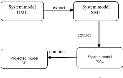
Any tool used to create or edit UML models should be capable of exporting these models-as a complete project-in XMI. We may process this XMI, in a number of stages, to produce compiler-ready XML.
Extraction
An XMI document need not represent a complete project: many classes may be mentioned but not defined; action expressions may be informal, or contain syntactic errors; some classes may be missing state diagrams. It may also contain information that is irrelevant to the chosen test directive.
This aspect of the processing task can be characterized using a meta-model for the output format: compiler-ready XML. In the current, prototypical version of the architecture, it is carried out by a Java program, using standard DOM (Document Object Model) libraries.
Transformation
Our test directive may contain object diagrams that are intended to exclude specific configurations or states. For each of these diagrams, we may apply a simple transformation to the state diagrams in the XML document.
An <<exclude>> object diagram will describe a configuration to be avoided in terms of the states of various objects. We may rewrite the state diagrams for these objects to render these states inaccessible. In each diagram, this will entail the removal of one or more states, along with the associated transitions.
The result is a projection of the system model in which the specified states are never explored; none of the tests that are subsequently generated will involve visits to these states.
If we wish to include particular states in our tests, then we may wish to detect, externally, that these states have been reached-we may then discard any test that does not do this. Furthermore, we may wish to add a controllable operation that takes the system into such a state.
Working from <<include>> object diagrams, we may wish to add transitions to the state diagrams of the model. These represent observable events and controllable operations in a testing interface.
Finally, we may wish to insist that each test produced ends with the system in a particular configuration. Working from a <<finish>> object diagram, we may add an observable event to detect this configuration.
The transformations described here are merely examples of what can be achieved. If our focus were animation, or verification, of the model, then we would not wish to exclude states in this
fashion; however, we may wish to apply a more complex transformation that achieves abstraction or
encapsulation
Each of the transfor mations may be implemented as a separate program in Java, or any other language; we may then pipe these programs together to produce a processing pipeline, taking the exported XMI representation to compiler-ready XML: see Fig. 3.
At any stage, up to compilation, the XML representation can be transformed back to XMI, using a transformer written in XSLT, allowing visual inspection in any UML tool.
Compilation
The Intermediate Format (IF) language was developed to sit between high-level specification languages, such as LOTOS², and tool-specific internal representations. IF representations can be passed between tools, and translated into other languages: for example, users of the CADP toolset6
can analyse their models using the SPIN model-checker¹².
In IF, each of the objects in our specification is represented as an extended finite state machine, or process. The state of each process-the values of local variables-is private; processes evolve and communicate by sending and receiving signals along specified signal routes.
export
.
extract
compile
transform System model
UML
System model XML
Projected model
IF
System model
XML
A signal route can be reliable or lossy, peer-to-peer or multicast, FIFO or multiset, timely or delayed. At present, we consider only reliable, peer-to-peer communication between objects, but there is considerable potential within the language, and hence the architecture, for alternative abstractions. As in UML, the arrival of a signal may trigger a transition between states, accompanied by a specified sequence of actions. This sequence may involve sending signals to other processes, or changing the values of local variables.
The process of compilation from XML to IF revolves around the state diagrams of our model; each of these will be transformed into an IF process. The initial (or start) object diagram for the model (or test) defines the initial configuration of processes. The class diagram provides information about data types and operations.
The translation into IF defines an effective semantics for the UML language of state diagrams. We need to define:
• an IF signal for each operation;
• an acknowledgement signal, including a retur n value parameter, for each synchronous operation;
• a process for each object in the model; • a communication buffer for each object.
States
Each state in a state diagram is translated into an IF control state, with stability and initiality attributes. If a state is marked as unstable, then any transaction through this state-a transition to, and a transition from-is treated as atomic, across the system. If a state is marked as initial, then it is treated as an initial state of the process.
A start state in a state diagram becomes an :init state in IF; a finish state becomes a state with no transitions. To translate a simple state, we append the entr y actions to ever y incoming transition; prepend the exit actions to every outgoing transition; transform any internal transition into an external, self transition, but without entry or exit actions.
Transitions
Having mapped the object states into IF,
we can construct a transition in IF for each transition in the state diagram:
from currentState
input operationName from thisBuffer if guard
do action ;
[ output ack(returnValue) to callerBuffer ] to newState
The output clause is used only in response to synchronous operations, modeled as call actions.
Events
A call event represents an operation invocation in which the caller will be notified of completion, and provided with any return value. We translate call events into IF signal inputs:
input operation-name (reference-list) from buffer
where operation-name is an operation of the current object; reference-list is a list of variables in which the received parameters are stored, buffer the name of the buffer from which the event will be read.
To achieve synchronisation with the caller object, we add a symmetrical action after every signal input representing a call event, sending an appropriate completion or return signal to the caller. A signal event represents the reception of a UML signal-used to model asynchronous communication. We translate signal events directly into IF signal inputs: input signal (reference-list) from buffer but this time there is no matching acknowledgement action.
Guards
These are translated into post guarded inputs where the received parameters can be tested; this guard is evaluated after the input is done and, if false, the execution of the transition is disabled, restricting the values that the process is willing to accept. In our modeling language, guards will be expressed by IF expressions.
Actions
additional, stable state to the IF representation of the object. This is the state in which the object has issued the call, but the operation has yet to return. If the state diagram has a transition from State1 to State2, labelled with call action a, then we obtain an IF representation of the form
from State1
input event from callerBuffer if guard
do action ; to StateX
from StateX
input ack_a from calleeBuffer to State2
Each send action becomes an IF output:
output signal(parameters) to targetBuffer
This has the effect of appending the specified signal to the buffer associated with the target object.
DISCUSSION
The work described here is still in progress. An architecture has been defined, and a software tool has been constructed to convert exported XMI projects into compiler-ready XML descriptions. The compiler itself has yet to be written; all of the examples used thus far have been translated-from UML directly into IF-by hand.
Although most industry testing of complex software is conducted at the system level, most formal research has focused on the unit level. As a result, most system level testing techniques are only described informally. This paper presents a novel technique that adapts pre-defined state-based specification test data generation criteria to generate test cases from UML state charts. UML state charts provide a solid basis for test generation in a form that can be easily manipulated. This technique includes coverage criteria that enable highly effective tests to be developed. To demonstrate this technique, a tool has been developed that uses UML state charts produced by Rational Software Corporation’s Rational Rose tool to generate test data.
Experimental results from using this tool are presented.
There is an increasing need for effective testing of software for complex safety-critical applications, such as avionics, medical, and other control systems. These software systems usually have clear high level descriptions, sometimes in formal representations. Unfortunately, most system level testing techniques are only descr ibed informally. This paper is part of a project that is attempting to provide a solid foundation for generating tests from system level software specifications via new coverage criteria. Formal coverage criteria over testers ways to decide what test inputs to use during testing.
Using UML
The use of UML as the language of models and test directives has significant advantages: • the graphical notations are familiar and
accessible to most software engineers; • a large number of tools exist for creating and
editing models.
It has also significant disadvantages:
• the semantics of communication within UML is only partially defined;
• the language provides features that can be used to create models of deceptive complexity.
We have dealt with the first of these by defining a semantics for the action–event mechanism; one that can be used to model both synchronous and asynchronous communication. The second is harder to deal with; we need to assess the value of each language feature.
Run to completion A state diagram accepts events one at a time. Subsequent events will be blocked until the current sequence of actions has been completed, and all active regions have reached the next stable state. This property is called the run to completion assumption, and it has implications for our use of the notation.
processed. If two objects (or a cycle of objects) are able to call synchronous operations on each other, then a deadlock may result: each object is unable to complete its current action until the next accepts an event; in the meantime, it cannot accept an event itself. If an action represents an operation call on the current object, then this cannot be regarded as a synchronous operation for the purposes of the event mechanism, or deadlock would be immediate. It may be asynchronous, but the results may be unexpected: the actions associated with the call will be postponed until the current sequence of actions has been completed.
The task of modeling concurrent behaviour purely in UML-without the assistance of a suitable formal semantics-is made more difficult by flexibility in the language definition. The relationship between an action and the corresponding event is left as a semantic variation point.
Composite states In the state diagram notation, states may be included in other states. Indeed, every state in the diagram is included in a single, outermost state. A state that includes others is said to be composite; a composite state defines a region of the state diagram, a fact that has semantic importance when we come to consider the arrival of events.
There are two kinds of composite state. A sequential composite state defines a region with a single flow of control; a concurrent composite state defines two or more regions, each of which is itself a sequential composite state. The concurrency in such a state is limited to the performance of actions: if an event is processed that triggers transitions in more than one regions, then the sequences of actions from each region may be arbitrar ily interleaved.
At present, the translation to IF does not exploit the composite state mechanism; every state in the diagram is included explicitly in the IF process. The forthcoming version of the IF language adds support for substate processes; we may therefore hope to reduce the complexity of our projected model by encapsulating states.
However, in UML notation, a transition
arrow may be drawn between any pair of states in the diagram. We may cross boundaries between regions, entering or leaving a series of composite states. This flexibility may be superficially attractive, but greatly increases the potential for confusion. It also prevents the use of composite states as an encapsulation mechanism.
Deferred events In state diagrams, simple or composite states may be associated with an additional attribute, a set of deferred events. If a deferred event occurs, then it is placed in a local queue-one that cannot be accessed outside the current region of the state diagram; it will occur again immediately after the next external transition.
If an event outside the deferral set occurs, and no transition of the current state is associated with it, then it will be ignored. The effect is exactly the same as if the event had occurred, but the corresponding guard was false: the event is processed-removed from the input queue, but no actions are performed; neither is there any change in state. If deferred events are used with composite states, then the resulting model will be too complex for use in test generation. Each region has its own queue of deferred events, and this queue must be checked, and filtered, at each transition. This problem is compounded in the presence of boundary crossing transitions.
Related work
The prospect of some degree of automation in the testing process is clearly an attractive one. Computing is becoming more pervasive, and more critical to our lives; at the same time, designs are becoming more complex, and interactions between components are becoming harder to measure and predict. Software testing is becoming more difficult, and more expensive.
A considerable amount of research has been carried out into the application of Finite State Machine (FSM) notations to testing, and test generation, particularly with regard to the testing of communicating systems17,15. This research solves
Other research, from theories of testing for State-Charts¹¹ and methods for behavioural model generation4, through to toolkits for automated
testing8, and packages for generating input
sequences for testing user interfaces14, has taken
a more pragmatic, industrial approach. Of these, only one8 presents an architecture: a precursor to
that adopted for the AGEDIS project.
There are several reports of success in automated test case generation. One of the examples5 includes the comment:
However, questions remained about the scalability of the approach. . . A state-machine based approach. would perhaps be more appropriate.
The focus of our research is exactly this: we are working towards scalable methods for automated test generation, using object-oriented principles, and building on fundamental research from the world of finite state machines.
ACKNOWLEDGMENTS
The authors would like to acknowledge the support of the EU AGEDIS project (AGEDIS 1999-20218)-and, in particular, the contributions of Laurent Mounier, Thierr y Juron, YvesMarie Quemener, Alan Hartman, and Ken Nagin—and the support of IBM, through their Faculty Partnership Program.
1. M. Bozga, J. Cl, F. Ghirvu, S. Graf, J. Krimm, L. Mounier, and J. Sifakis. IF: an intermediate representation for SDL and its applications. In SDL FORUM 99 (1999).
2. Ed Brinksma and Tommaso Bolognesi.
Introduction to the ISO specification language LOTOS. Computer Networks and ISDN Systems, 1987.
3. Rational Software Corporation. Rational Rose. June 2001, http://www.rational.com. 4. Ibrahim Khalil Ibrahim El-Far. Automated
construction of software behavior models. Master’s thesis, American University of Beirut, 1995. http://se.it.edu/ielfar/thesis.pdf. 5. M. S. Feather and B. Smith. Automatic generation of test oracles-from pilot studies to application. Automated Software Engineering, 8(1): 31-61 (2001).
6. J. Fernandez, H. Garavel, A. Kerbrat, R. Mateescu, L. Mounier, and M. Sighireanu. CADP: A protocol validation and verification toolbox. In CAV ’96: 8th Conference on Computer-Aided Verification, (1996). 7. Jean-Claude Fer nandez, Claude Jard,
Thierry Jeron, and Cesar Viho. An experiment in automatic generation of test suites for protocols with verification technology. Science of Computer Programming, 1997.
citeseer.nj.nec.com/2326.html.
8. I. Gronau, A. Hartman, A. Kirshin, K. Nagin, and S. Olvovsky. A methodology and architecture for automated software testing. h t t p : / / w w w. h a i fa . i l . i b m . c o m / p r o j e c t s / verification/gtcb/papers/gtcbmanda.pdf, 2000.
9. Object Management Group. OMG XML
Metadata Interchange (XMI) specification, version 1.1, November 2000. http:// www.omg.org/cgi-bin/doc?formal/2000-11-02.
10. Object Management Group. Unified Modeling Language (UML) 1.4 draft, February 2001. http:/ /www.omg.org/cgi-bin/doc?ad/2001-02-13. 11. David Harel and Eran Gery. Executable object
modeling with statecharts. In Proceedings of the 18th Inter national Conference on Software Engineer ing. IEEE Computer Society Press, 1996.
12. Gerard J. Holzmann. The model checker SPIN. Transactions on Software Engineering, 1997.seer.nj.nec.comholzmann97model.html.
13. The AGEDIS project, 2000. “http://
www.agedis.de”.
14. S. Rosaria and H. Robinson. Applying models in your testing process. Information and Software Technology (2000).