Tribology in Industry
www.tribology.rsMethod of Accelerated Testing of Crankshaft Shells
of the Combustion Engine in the Operating Process
O. Grytsyuk
a,
O. Vrublevskyi
b,*
aKharkiv National University of Automobile and Highways, Kharkov, Jaroslawa Mudrego 25, 61-002 Charków, Ukraina, bUniversity of Warmia and Mazury in Olsztyn, Oczapowskiego 11A, 10-736 Olsztyn, Polska.
Keywords:
Combustion engine Crankshaft bearing Accelerated test Wear
Oil spectrograph
A B S T R A C T
This article discusses the method and results of accelerated tests of crankshaft bearings of the compression ignition engine, carried out to determine the possibility of modernising the basic engine model and improving the methods of friction joint diagnostics. The essence of the method consists in changing the operating conditions of the crankshaft bearings of one of the engine cylinders. This increases the bearing load and causes changes in the engine oil temperature. The bearing condition was monitored non-invasively by determining the share of wear products in the oil samples. The results obtained from the tests have shown that on the basis of oil analysis for the presence of wear products, the cause of engine failure related to the acceptable wear of engine friction pairs can be clearly identified and located.
© 2019 Published by Faculty of Engineering * Corresponding author:
Oleksandr Vrublevskyi Email:
Received: 26 September 2019 Revised: 29 October 2019 Accepted: 22 November 2019
1. INTRODUCTION
Compression ignition engines (CI) are currently, and in the future will be, the basic source of drives for trucks, buses or tractors. The latest trends in the design and manufacture of CI engines are aimed at increasing the crankshaft rotational speed [1], limiting the piston stroke, reducing the engine geometry [2,3] and increasing the actual compression ratio and maximum combustion pressure [4]. These solutions increase oil temperature and contact stresses at friction joints. In such conditions, friction pairs operate in much more difficult conditions than in engines operated 15-20 years ago. Over the last decade, the leading car manufacturers have been offering a warranty
period of at least three years [5,6]. At the same time, in order to reduce operating costs and cope with competition in the market, the time between oil changes in engines has been extended. It should also be emphasised that a modern car, and especially the engine, are designed for a specified period of use [7]. At the same time, the aim is to change the model frequently, which is economically attractive for manufacturers. The importance of the issue of the accelerated implementation process of new energy conversion and green transport technologies should be emphasised. This justifies the cancellation of the design of new vehicles with increased durability and reliability. Designing engines with specified durability requires a new approach to tests, aimed at
R
ES
EA
R
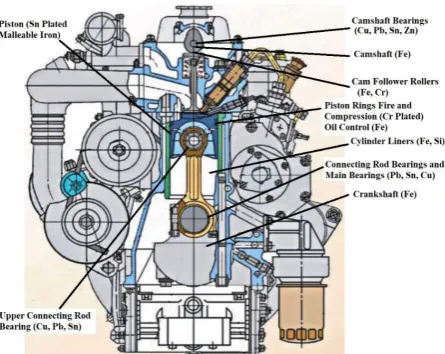
identifying important joints while designing in the aspect of changing conditions of use. It is important to determine the time of the occurrence of the borderline change in the technical condition of the structural elements forming the friction joints. Such CI engine joints cover a piston-crank system, also including the crankshaft and camshaft bearings (Fig. 1).
Fig. 1. General view of the lubrication system and
crankshaft friction units engine: 1-4 cylinder sequence; 5 – parts of the connecting rod bearing; 6 – parts of the main bearing.
Based on the analysis of energy consumption resulting from friction in passenger cars [8] as well as trucks and buses [9] and own research [10], aimed at determining critical friction elements that determine the value of CI engine loss torque during starting, crankshaft bearings generate up to 30 % of the total friction losses in the engine (Fig. 2).
Fig. 2. Engine friction distribution.
Operating conditions of these bearings mainly result from significant and high dynamics of load changes occurring at the moment of combustion up to 10 MN/s, temperature exceeding 100 °C and variable rotational speed of the crankshaft in the range from 0 to 470 rad/s. So far, no alternative
solutions for the indicated structural elements have been developed. It is indicated that these solutions are characterised by many important advantages [11]. The processes occurring in these elements are describe by the hydrodynamic [12], thermal [13] and tribological theories [14,15] relatively well. Taking into account the significance of these joints for the correct functioning of the entire engine, there is a need to conduct tests aimed at online evaluation of the wearing degree of journal bearings, develop criterion values and determine the probability of engine damage as a function of oil ageing.
As a rule, the process determining the system
status includes the following stages:
measurement of the parameter and comparing it with the criterion value; analysis of the nature and causes of possible deviations; presentation of projects to obtain the system probable average values or to restore the proper operation.
The course of the wear process is unnoticeable and random, and its effects are quite difficult to predict. However, it is possible to obtain information about the nature and degree of wear with the use of accelerated tests. They can be carried out under laboratory conditions based on the physical model of functioning of the object tested [12,16,17]. This is related to the adoption of a number of assumptions that, to some extent, reduce the reliability of results. Another option is to perform accelerated tests under real operating conditions. Accelerated tests of tribological objects are conducted with the same damage mechanisms as under normal operating conditions, but in much shorter (10-15 times) time. The damage mechanism is accelerated by changing one or more parameters. In this case, it is possible to obtain reliable data not only about the wear process and operational potential of the object, but also about observing the impact of the conditions of use of the object on the engine as a whole.
The conditions for the implementation of accelerated tests of the tribological object are connected with the need to solve a number of
tasks. They include: development and
2. AIM AND SCOPE OF THE WORK
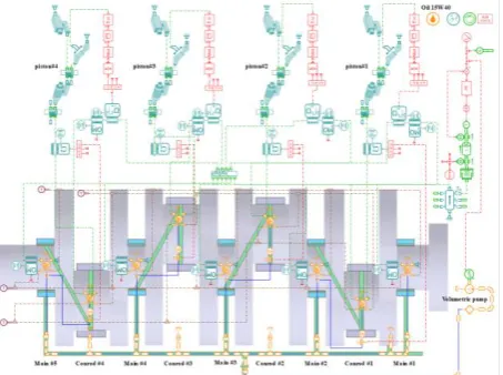
Identification of the damage process in modernised CI engines with increased (by 20-30 %) power; accelerated testing of friction pair is groundless in the running-in period. The phenomena of this period are the subject of separate studies. The decisive factors in this period are the properties of the materials obtained during the application of anti-wear coatings and special covers. The phenomena accompanying the running-in period prevent the unequivocal identification of wear as well as technological and construction factors affecting its nature during operation. The tests of friction pairs under operating conditions were carried out in a 4DTNA1 [18] engine mounted in a light-duty truck (LDV). Wear products in oil result from the processes taking place in the following friction pairs - cylinder-piston system, crankshaft, camshaft, auxiliary mechanisms (Fig. 3). Among the wear products, the elements containing Pb, Sn, Cu, Fe characteristic for engine journal bearings were identified. The basis for the evaluation of the current technical condition of the tested elements was the content of individual metals in the oil samples taken. This will clarify the maximum allowable concentration of wear products, defined to maintain proper engine operation.
Fig. 3. 4DTNA1 elements used in the engine found in
the oil analysis.
3. RESEARCH FACILITY
3.1 Accelerated test conditions
It was found that among the working factors, the dynamic nature of the load has the greatest
impact on the bearing wear process [19]. This statement is correct when other factors such as the manufacturing technology and the material of the shell and the journal, the initial lubrication conditions, the change of the crankshaft rotation frequency, physical and chemical properties of oil at the beginning of the experiment and the mounting technology are the same.
The bearing load is increased as a result of changing the conditions of fuel supply to individual engine cylinders. Due to the strength conditions for this engine, the maximum possible combustion pressure should not exceed 15 MPa. The test results obtained so far have shown that with the increase in the fuel dose to the values specified in Tab. 1 and adjustment of the beginning of fuel injection, there is an increase in forces acting on the bearings during the combustion process expansion (Fig. 4).
Table 1. Cycle supply of fuel in the characteristic
points of the external velocity characteristic during accelerated tests.
shaft speed,
rpm fuel delivery to cylinders q, mm
3/cycle
1 2 3 4
1600 30.5 58.5 36 35
3000 35.5 54 37.5 34.5
Fig. 4. The dependence of the relative cycle supply to
the force acting on the main and connecting rod bearings of the crankshaft during combustion-expansion.
For the presented values, these are the least favourable conditions for the lubrication of
crankshaft bearings. Computational and
mode, one should expect accelerated wear of the connecting rod bearing on the cylinder to which the increased fuel dose will be supplied. Accordingly, when operating a vehicle outside built-up areas (e.g. on a motorway), a significant increase in the wear of the connecting rod bearings should be expected.
To test the proposed methodology for accelerated tests of bearings, a thermal-hydraulic bearing model (Fig. 5) with 3D mechanical ports allowing the load and mobility calculations was used. The model is made in the software package Simcenter Amesim. In contrast to the crankshaft model from the library of examples of the Simcenter Amesim software package, the model used in the study allows you to set the pressure for each cylinder separately. To study the influence of hydrodynamic processes in the lubrication system on the operation of bearings, elements of this system are included in the model. This model
computes bearing eccentricity oil film
characteristics (minimum oil film thickness, maximum pressure, oil film angles) and oil flow rate. The geometry of the oil inlet can be modelled with a single hole, a partial or a full groove. Oil feeding is done through the bearing model and provides 3D torque and load calculations, including dry friction and elastic contact. Hydrodynamic effects (pumping effect) due to eccentricity variations and rotary velocity can be taken into account.
Fig. 5. General view and computational scheme for a
crankshaft.
For the type of thrust bearing when tested with 0.25≤B / D≤1, where B is the width of the bearing; D is the diameter of the bearing. To solve the Reynolds equation, the Goenko method [20] was used. If we take into account the
hydrodynamic effects, the total volumetric flow rate Qt of oil through the bearing is calculated from the equation of Martin et al. [21]. The data for model identification were obtained based on the calculations of processes in crankshaft bearings using the above-described principles of hydrodynamic lubrication. The dependence was applied on a minimum oil layer in main crankshaft bearings for various crankshaft rotational speeds and a minimum idle run frequency of 800 rpm up to nominal load frequency at 3,000 rpm (Fig. 6). A change in the depth of wear of burnishing PbSn and CuPb antifriction surfaces of the bushing (Fig. 6), which were used in a vehicle with a mixed driving cycle with an odometer reading of 20,600 km, may depict the results of the calculations.
Fig. 6. Comparison of calculated oil film in the main
bearing of cylinder # 1 with an image of the bushing and wear patterns.
Fig. 7. Comparison of journal centre orbit main
bearings (3,000 rpm).
in the course of operation. The analysis was carried out based on a comparison of the change in the location of the journal center (Fig. 7). As the fuel supply to the second cylinder is increased (Table 1), the largest area created by the trajectory of the main journal center displacement in the plane perpendicular to its axis refers to the second main bearing (Fig. 7). The maximum eccentricity in the second bearing is 0.068, while in the rest it does not exceed 0.058. The intensification of the journal center displacement caused by the increase of the fuel supply accelerates the wear process of the bearing shells and the bearing journal.
The second factor significantly affecting the wear intensity of journal bearings is the temperature of the collaborating surfaces [22]. Accelerated tests in the conditions of increased temperature of the coolant within the specific engine operation time (not exceeding 18 hours) allow obtaining information on the technical condition of the crankshaft bearings.
The change of local lubrication conditions in tribological units was made to one of the engine operating cylinders. Based on the analysis of the evaluation of the technical condition of the crankshaft bearings, the use of an accelerated test was suggested for the tribological joint under operating conditions. It was assumed that the cooling system in urban areas is stabilized at 90 °С. In non-urban areas, e.g. in motorway traffic, the coolant temperature increases up to 95-105 °С due to the change in the operating conditions of the fan viscous clutch.
3.2 Selection of a single friction unit
The operating conditions of the friction joints of the crankshaft in the engine tested depend not only on the operating factors, but also on the decisions made when designing its systems. For accelerated tests, taking account of the lubrication system (Fig. 1) the bearing joint of the second cylinder has been selected.
Due to the power supply conditions and the oil pressure levels achieved with a four-cylinder engine, the crankshaft bearings can be divided into two groups (Fig. 8). The first group is used at a lower pressure, and therefore the worst ablation of wear products. It includes the bearings of the first and fourth cylinders.
Selecting the study subject among them is pointless. This is due to the fact that oil is used as an "indicator" of the presence of wear products. Therefore, the use of this feature for the bearings of the first group may not reflect the current state of the object. The second group includes the bearings of the second and third cylinders. In this case, the ablation of wear particles with oil is more favourable and the bearing temperature depends on the operating conditions of the lubrication system and is less susceptible to additional external factors. In addition, the choice of, for example, the second cylinder enables a comparison of the main and connecting rod bearings in the next stage of accelerated and normal wear.
Fig. 8. Relative change in pressure in the lubrication
system at a rated load on 3,000 rpm.
Accordingly, the analysis of the wear conditions was carried out for the bearings of the second cylinder to which the oil supplied is characterised by the lowest pressure loss. As a consequence, the impact of additional factors influencing consumption was eliminated during the tests.
3.3 The choice of "indicator" characterizing the course of the wear process in the object
Identification of these quantities requires disassembly. This is not consistent with the idea of the diagnostics itself. Therefore, a method was suggested that was based on the analysis of the concentration of wear products in oil taken from the lubrication system at specified times in the operating process. It is a measure of the wear "indicator" defined on the basis of accelerated tests under operating conditions.
Based on the basic assumption of the wear
process (Lorenz curve), consisting in
distinguishing three separate stages of normal wear - running in, normal operation and accelerated wear, the test start time was determined after the end of the running in the stage. The oil chemical composition was examined using a spectrographic analysis. In tests, the limit value of the oil viscosity is reduced by 20 % in relation to the new oil at 100 °C.
3.4 Measuring apparatus
The evaluation of the content of elements in wear products in the oil was carried out by spectral analysis using the MFS-7 spectrograph (Tables 2 and 3). The analysis process is automated from the moment of installing the sample on a tripod, and the results of the concentration analysis are then presented on the display screen and transferred to the computer memory and printed.
Table 2. Specifications of the spectrograph MFS-7.
Parameter Value
The number of simultaneously
analysed elements to 24
The duration of the analysis of one
sample (without sample preparation) 2 - 3 min Range of detectable concentrations from 0.3 to 300 ppm
Focal length 1 m
Operating spectrum with a grid of
1800 lines/mm 200 - 400 nm
Inverse linear dispersion 0.55 nm/mm
Table 3. The limits of detection of engine wear
products in lubricating oils and the convergence of measurement results for average concentrations.
Element Wavelength, nm limit, ppm Detection Convergence, %
Fe 259.9 0.2 7.0
Cr 267.7 0.1 4.0
Pb 283.3 0.3 5.0
Si 288.1 0.3 4.0
Al 308.2 0.2 12.0
Sn 317.5 0.1 4.0
Cu 327.4 0.1 6.0
4. ANALYSIS OF THE TEST RESULTS
The frequency of sampling and the test results obtained are shown in Figs. 9–11. The nature of the change in the number of all components of wear products indicates that the transition from the running-in state to normal operation occurs after 1,500 km of mileage (Figs. 9 and 10). It should be noted that the analysis of the oil was carried out after the completion of accelerated tests, the replacement of bearings and oil. Similar values of the running-in period located at 1100 km were obtained (Fig. 11).
Fig. 9. Changes in the content of Fe, Pb and Cu in
engine oil samples depending on the vehicle mileage.
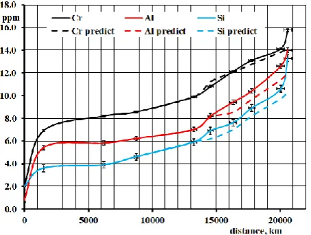
Fig. 10. Changes in the content of Cr, Al and Si in
engine oil samples depending on the vehicle mileage.
running-in, contains similar fractions of Cr, Pb, Si, Cu (2-3.4 ppm). It was found that the bearing alloy of the crankshaft shell is the source of Pb and Cu in the oil (Fig. 11).
Fig. 11. Changes in the content of Fe, Cu, Cr, Al, Pb
and Si in engine oil samples depending on the vehicle’s mileage after conducting accelerated tests to replace damaged elements and oil.
After obtaining the results (Figs. 9-11), it can be generally concluded that the nature of the changes in the concentration of the wear products in the oil samples is consistent with the Lorenz curve. It is possible to distinguish the running-in period, normal operation and accelerated wear up to damage during the engine operation.
The content of elements such as Fe (17.9 ppm) and Cr (2 ppm) is mainly due to the wear of the collaborating parts of the cylinder-piston units and the engine shafts. The camshaft bearings, as well as the engine auxiliary components and the reloading, are the source of the Al content (0.75 ppm). The change in the content of individual wear products after a mileage of 1,500 km reveals different dynamics. The unit content of elements, related to the distance driven, shows a relative increase and amounts
to Fe (0.00587 ppm/km), Pb (0.0058 ppm/km) and Cr (0.0033 ppm/km). The presence of these elements in combination with Si is usually the result of friction processes in the cylinder-piston unit, including the piston, rings and the cylinder. In addition, the content of Al (0.00303 ppm/km) and Cu (0.00313 ppm/km) was found in the wear products. The content of Si (0.001 ppm/km) was slightly less. The accelerated increase in Pb and Cr content indicates the running-in processes in journal bearings (Pb - wear of the upper bearing layer) and piston rings (Cr). Obviously, it should be noted that the dynamics of Fe growth, the source of which is the largest number of engine structural components, is almost the same as for Pb and Cr. The contents of individual elements in the period of stabilised wear, recorded on the basis of the content of wear products in the oil in a mileage range from 1500 to 13250 km, with an evenly distributed collection frequency, are shown in Fig. 9 and 10. Considering the average dynamics of the increase in the content of wear products in a given time, with the exception of Fe, whose index (0.00682 ppm/km) even exceeds the values for the running-in period, all other elements have a slight (from 0.00026 - Cr to 0.0007 - Cu) dynamics of the content increase (Tab. 4). It should be emphasised that the more kilometres driven, the more significant was the increase in the content of Si in the oil.
This is caused not only by the effect of wearing (this component is an addition of aluminium-based alloys), but also by the presence of other sources of Si in the oil: from the air, from the oil defoaming agent, elastomeric seals or from silicone-based materials.
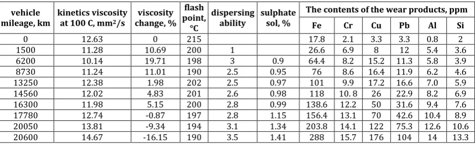
Table 4. Change in characteristics of oil samples in exploitation.
vehicle
mileage, km kinetics viscosity at 100 C, mm2/s
viscosity change, %
flash point,
°C
dispersing
ability sulphate sol, %
The contents of the wear products, ppm
Fe Cr Cu Pb Al Si
0 12.63 0 215 17.8 2.1 3.3 3.3 0.8 2
1500 11.28 10.69 200 1 26.6 6.9 8 12 5.4 3.6
6200 10.14 19.71 198 3 0.9 64.4 8.2 15.2 11.3 5.8 3.9
8730 11.24 11.01 190 2.5 0.95 76 8.6 16.4 11.9 6.2 4.6
13250 12.38 1.98 202 2.5 0.97 101 9.9 17.2 16.6 7.0 5.9
14560 12.02 4.83 201 2.6 0.98 118 10. 8 26 22.9 8.2 6.9
16300 11.98 5.15 200 2.8 0.99 138.6 12.2 50 31.6 9.4 7.6
17780 12.74 -0.87 197 2.8 1.15 156.4 13.1 70 42.6 10.4 8.9
20050 13.81 -9.34 194 3.1 1.34 203.8 14.1 122 75.3 12.6 10.6
More detailed attention should be paid to the characteristics of change in the content of Fe in oil samples (Fig. 9) after a mileage of 1,500 km. If the average dynamics of Fe changes in samples is of 0.00682 ppm/km, then on sections of 1,500-6,200 km and 8,730-13,200 km these
values are higher and amount to
0.00998 ppm/km (1,500-6200 km) and
0.00462 ppm/km (8,730 – 13,200 km). The indicated change in the content of Fe and other components causes not only the change in friction conditions, but also seasonal changes in the operating conditions of the vehicle. In winter, the engine warm up time increases which, in turn, leads to unfavourable conditions of oil film formation in bearings and increased oil viscosity. During tests in such conditions, the vehicle was operated in a mileage range from 1,500 to 6,200 km in the period of accelerated tests, i.e. from October 2017 to April 2018. Based on the statistical analysis of the results during the engine normal operation period, a prediction of probable concentration values of the wear products in the further operating process can be developed (marked with a dashed line in Figs. 9 and 10). For iron, for example, a change in concentration with a
probability of 0.9979 can be described as: СFe =
-2E-08L2 + 0.0067L + 18.37, where СFe is the
concentration of Fe; L is the mileage of the vehicle. The results obtained from the tests confirmed the data (Table 5) received from manufacturers of engine oil and engines.
Table 5. Comparison of limit values (ppm) for engine
oil and engine manufacturers with test results.
Element
Limit values from manufacturers
Start and end values for accelerated
testing
[30] [31] Start End
Iron (Fe) 100 80-180 106.8 288
Chromium (Cr) 10 4-28 9.96 15.76
Aluminium (Al) 20 12-55 7.4 13
Copper (Cu) 20 25-60 17.2 176
Lead (Pb) 25 10-30 16.5 104
Silicon (Si) 20 15-30 5.9 13.2
After a mileage of 13,250 km during the planned car operation, the operating conditions of the crankshaft friction pairs in the second cylinder were changed. The fuel supply was increased and the temperature conditions of the lubricant were changed. The tests were carried out outside the city. The duration of the accelerated tests, and thus the transformation of the normal
operating period into accelerated wear, was determined based on the moment of an emergency situation occurring related to the critical wear of the bearings tested. An analysis of oil samples during the accelerated test period was carried out with a scheduled frequency of 1,500 km. This is the period recommended by vehicle manufacturers under actual operating conditions. The actual frequency of oil sampling is shown in Tab. 4.
The analysis of the results of accelerated tests shows that in comparison with the predicted wear indicators (Figs. 9 and 10) an increase in Fe, Pb and Cu in oil samples was noted. This increase amounted to 1.91; 4.81 and 6.46 times respectively. At the same time, compared to the predicted values, the conditions of accelerated tests had little effect on the content of Cr, Al and Si in the oil. The concentration of these elements increased by 1.12-1.29 times compared to the predicted value. This indicates the validity of the assumptions made in the adopted methodology of crankshaft bearing tests.
The analysis of the dynamics of the increase in the concentration of wear products in oil samples makes it possible to distinguish two periods in the engine operating process. The first from 13,250 to 17,780 km is characterised by a slight increase in the wear dynamics for each of the elements analysed. The exceptions are Cu and Pb, whose concentrations start to increase from the beginning of the accelerated tests. These elements are contained in the crankshaft bearing shells.
The second period of accelerated tests ranges from 17,780 to 20,600 km. At the end of this period, the test was terminated due to the total wear of the main bearing shells of the second cylinder (Fig. 12b). During this period the concentration of Cu, Pb increases 13.7 and 15.8 times, respectively.
to 26 g (connecting rod side) and by 17.5 g (cover side). At the same time, the weight of the connecting rod shells of the first cylinder (Fig. 12a) was reduced by 1 g.
a)
b)
Fig. 12. Photos of connecting rod bearing shells: a)
first cylinder; b) second cylinder.
After changing the crankshaft bearing shells of the second cylinder, engine oil, lubrication system filter, the car and the tested engine were brought back to operation. Continuous monitoring of the oil characteristics indicates a satisfactory state of the crankshaft friction units. At the end of 2018, the mileage of the vehicle amounted to 25,600 km.
5. CONCLUSIONS
The tendency to design products with definite durability requires a new approach to testing the lifecycle of a technical object. It is particularly important to determine the time limit of the change in the technical condition of the structural elements forming the friction units. Such engine
components cover the piston-crank system, also including the crankshaft and camshaft bearings. The oil change in modern vehicles is not used more and more often in order to reduce operating costs and ensure comfort (to meet the market competition) for customers. This requires an improvement of the methods of determining the physical and chemical properties of the oil in operation and determining the limit levels of the concentration of the wear products during the accelerated tests.
The suggested test method consisted in increasing the fuel dose to one of the cylinders and the temperature of the coolant while driving the car on the motorway. The concentration of elements in the engine oil samples taken at specified times during operation was assumed as the factor determining the process of wear at work.
The results from the tests have shown that by analysing the oil samples for the presence of wear products, the cause of engine failure related to the critical wear of friction pairs can be clearly identified and located. The characteristics of changes in the concentration of wear products in oil samples are in line with the Lorenz curve, by means of which they show the running-in period, extended normal operation and accelerated wear to failure.
The results obtained from accelerated tests indicate that the wear process is 13 times faster than in the normal conditions of the operation of bearings, which corresponds to the estimated mileage of the vehicle of 60,000 km.
The suggested accelerated test method can be used to precisely adjust and test tribological joints, including journal bearings operating under variable load conditions, oil pressure and ambient temperature. It may also form the basis for developing and creating new methods for diagnosing tribological elements.
REFERENCES
[1] J.B. Heywood. Internal Combustion Engines Fundamentals. Singapore: McGraw-Hill Book Co, 1988.
pp. 31-37, 1994, doi: 10.1016/0301-679X(94)90060-4
[3] D.E. Sander, C. Knauder, H. Allmaier, S. Damjanovic, L. Baleur, P. Mallet, Friction Reduction Tested for a Downsized Diesel Engine with Low-Viscosity Lubricants Including a Novel Polyalkylene Glycol, Lubricants, vol. 5, iss. 2, pp. 1-14, 2017, doi: 10.3390/lubricants5020009 [4] D.E. Sander, H. Allmaier, H. Priebsch, F. Reich, M.
Witt, T. Füllenbach, A. Skiadas, L. Brouwer, H. Schwarze, Impact of high pressure and shear thinning on journal bearing friction, Tribology International, vol. 81, pp. 29-37, 2015, doi: 10.1016/j.triboint.2014.07.021
[5] Dodge. Warranty Information’s, p. 44, 2015, www.dodge.com/crossbrand/warranty/pdf/ 2015-Dodge-Generic_Warranty-1st.pdf accessed: 23.11.2018.
[6] Mercedes-Benz Extended Limited Warranty. p. 5, 2017, www.mercedes-benz.ca/en/owners/ service-maintenance/vehicle-warranty
accessed: 23.11.2018.
[7] J. Gonera, J. Napiórkowski, Model for forecasting the geometry of the floor panel of a passenger car during its operation, Maintenance and Reliability, vol. 20, no. 4, pp. 689–695, 2018, doi: 10.17531/ein.2018.4.20
[8] K. Holmberg, P. Andersson, A. Erdemir, Global energy consumption due to friction in passenger cars, Tribology International, vol. 47. pp. 221– 234, 2012, doi: 10.1016/j.triboint.2011.11.022 [9] K. Holmberg, P. Andersson, N.-O. Nylund, K.
Mäkelä, A. Erdemir, Global energy consumption due to friction in trucks and buses, Tribology International, vol. 78, pp. 94–114, 2014, doi: 10.1016/j.triboint.2014.05.004
[10] Y. Borodin, O. Grytsyuk, D. Demidenko, V. Kondratenko, Identification of critical friction points that determine the moment of resistance of an autotractor diesel engine during its start, Internal combustion engines, no. 1, pp. 60-63, 2002.
[11] J.-L. Ligier, B. Noel, Friction Reduction and Reliability for Engines Bearings, Lubricants, vol. 3, pp. 569-596, 2015, doi: 10.3390/lubricants 3030569
[12] D.E. Sander, H. Allmaier, H.H. Priebsch, M. Witt, A. Skiadas, Simulation of journal bearing friction in severe mixed lubrication – Validation and effect of surface smoothing due to running-in, Tribology International, vol. 96, pp. 173-183, 2016, doi: 10.1016/j.triboint.2015.12.024 [13] D. Singh, F. Gu, J. D. Fieldhouse, N. Singh, S.K.
Singal, Prediction and Analysis of Engine Friction Power of a Diesel Engine Influenced by Engine
Speed, Load, and Lubricant Viscosity, Advances in Tribology, vol. 2014, p. 9, 2014, doi: 10.1155/2014/928015
[14] J.L. Ligier, L. Dutfoy, Modelling and prediction of a simplified seizure mechanism occurring in conrod bearings, Mechanics Industry, vol. 12, no. 4, pp. 265–273, 2011, doi: 10.1051/meca/2011101 [15] Y. Okamoto, K. Kitahara, K. Ushijima, S. Aoyama,
H. Xu, G.A. Jones, A study for wear and fatigue on engine bearings by using EHL analysis, JSAE Review, vol. 21, iss. 2, pp. 189–196, 2000, doi: 10.1016/S0389-4304(99)00092-2
[16] S.M. Chun, Simulation of engine life-time related with abnormal oil consumption, Tribology International, vol. 44, iss. 4, pp. 426-436, 2011, doi: 10.1016/j.triboint.2010.11.020
[17] J. Zhu, D. He, E. Bechhoefer, Survey of Lubrication Oil Condition Monitoring, Diagnostics, and Prognostics Techniques and Systems, Journal of Chemical Science and Technology, vol. 2, no. 3, pp. 100-115, 2013. [18] O. Grytsyuk, O. Vrublevskyi, Investigations of
diesel engine in the road test, Diagnostyka, vol. 19, no. 2, pp. 89–94, 2018, doi: 10.29354/diag/90279
[19] B. Vasanthan, G. Devaradjane, V. Shanmugam,
Online condition monitoring of lubricating oil on test bench diesel engine & vehicle, Journal of Chemical and Pharmaceutical Sciences (ICRAMET’ 15), iss. 9, pp. 315-320, 2015. [20] P.K. Goenka, Analytical Curve Fits for Solution
Parameters of Dynamically Loaded Journal Bearings, Journal of Tribology, vol. 106, iss. 4, pp. 421-427, 1984, doi: 10.1115/1.3260950 [21] F.A. Martin, M. Stanojevic, Paper IV (iii) Oil Flow
in Connecting-Rod Bearings, Tribology Series, vol. 18, pp. 69–80, 1991, doi:10.1016/s0167-8922(08) 70122-6
[22] J.K. Wlodarski, Tlokowe Silniki Spalinowe – Procesy Trybologiczne. Warszawa: WKL, 1982. [23] F. Fenga, A. Si, P. Jianga, Fault Diagnosis for
Crankshaft Bearing in Diesel Engine Based on Bispectrum Analysis, Chemical Engineering Transactions, vol. 33, pp. 1033-1038, 2013, doi: 10.3303/CET1333173
[24] S. Gowtham, P. Rajesh Kumar, Condition Monitoring of I.C Engines by using Oil Analysis IJIRST, International Journal for Innovative Research in Science & Technology, vol. 2, iss. 12, pp. 370-375, 2016.
[25] H. Raposo, J.T. Farinha, I. Fonseca, L.A. Ferreira,
Buses, Actuators, vol. 8, iss. 1, 2019, doi: 10.3390/act8010014
[26] L. Du, J. Zhe, A high throughput inductive pulse sensor for online oil debris monitoring, Tribology International, vol. 44, iss. 2, pp. 175-179, 2011, doi: 10.1016/j.triboint.2010.10.022
[27] X. Zhu, C. Zhong, J. Zhe, Lubricating oil conditioning sensors for online machine health monitoring – A review, Tribology International, vol. 109, pp. 473-484, 2017, doi: 10.1016/j.triboint.2017.01.015 [28] K.W. Chambers, M.C. Arneson, C.A. Waggoner,
An on-line ferromagnetic wear debris sensor for
machinery condition monitoring and failure detection, Wear, vol. 128, iss. 3, pp. 325-337, 1988, doi: 10.1016/0043-1648(88)90067-1 [29] K. Nejjar, A. Zeriouh, L. Belkbir, M. Hamad,
Comparative Study Between Oil Analysis and Sludge Analysis of Marine Diesel Engines, Asian Journal of Chemistry, vol. 20, no. 1, pp. 361-365, 2008.
[30]
www.aviflex.de/assets/Uploads2017/Petro-CanadaLubricants2016 HandbookEnglish.pdf
[31] www.machinerylubrication.com/Read/30274/