1212
A NOVEL IMAGE STEGANOGRAPHIC SYSTEM BASED ON
EXACT MATCHING ALGORITHM AND KEY-DEPENDENT
DATA TECHNIQUE
MAHER A. ALSARAYREH 1, MOHAMMAD A. ALIA 2, KHULOOD ABU MARIA 3
1, 2, 3 Faculty of Science and Information Technology – Al Zaytoonah University of Jordan, Amman,
Jordan.
E-mail: 1[email protected], 2[email protected], [email protected]
ABSTRACT
Steganography is defined as the art of hiding secret information. It is used to guarantee information accessibility only by authorized parties. The least-significant bit (LSB) approach is one of the most important scenarios in steganography. However, the existing LSB approaches apply some changing in the image’s pixels values, which make the image suspected by intruders and hackers. This paper proposed an image steganography system based on the exact matching between the image’s pixel values and the secret data. As well as, a random key-dependent data (RKDD) is generated without performing any changes on the image’s pixel values. Moreover, the proposed system has been tested successfully on many images giving promising results. These significant results can be perceived in terms of fast searching time, great number of matches, reduced key size, achieving steganography performance criteria, invisibility, payload/ capacity and robustness.
Keywords: Steganography, Cryptography, Encryption, Information Hiding, Exact Matching Algorithm, Image, Secret message, LSB, and Key-Dependent Data Technique.
1. INTRODUCTION
Steganography is defined as the art of hiding secret messages within media, such as images, text, video, audio, and protocols [1]. It is also shared and interrelated common services of protecting the confidentiality, integrity, and availability of information. Image steganography is categorized into two main domains: image domain and transform domain. The image domain is also known as a spatial domain, which includes the embedding process. This domain is actually performed by changing image's pixel values. Currently, the least significant bit (LSB) and most significant bit (MSB) are considered as working examples in image domain [2]. On the other hand, the embedding process in the transform domain is implemented after converting the image into its frequency content such as Discrete Fourier Transformation technique (DFT) and Discrete Cosine Transformation technique (DCT) [3]. Additionally, transform domain is also introduced as a frequency domain. In general, Steganography
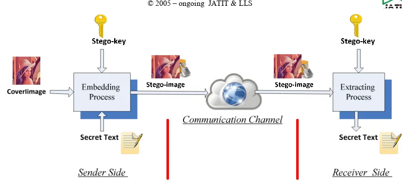
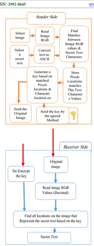
system consists of two main processes: embedding process and extracting process. In the embedding process, the produced image can be called as a stego-image or a cover image and is used to embed the secret data. For hiding data inside image pixels, all selected pixels must be chosen secretly by using a secret key which is commonly known as a stego-key. Whereby, recovering the hidden secret data will be then extracted by the receiver [4], as shown is Figure 1.
1213 1. Imperceptibility/Invisibility: implies that
exposed human eyes cannot separate between an image prior and the afterward hidden data [3]. Fidelity and quality are the only perfectibility metrics to distinguish and check the steganography systems. Fidelity is defined as the perceptual resemblance between the image before and after the embedding process. Quality is the integrity of the image before and after word the processing. Peak Signal to Noise Ratio (PSNR) and Mean Square Error (MSE) are a two fidelity parameters [5].
2. Payload/Capacity: clarifies the amount of secret data, which can be covered up in the cover image [1] [2]. Least Significant Bit (LSB) is the most prominent technique used for steganography where message bit is embedded in the LSB of the cover image pixel. This strategy is described by its high-capacity and imperceptibly with low robustness against attacks trying to separate the secret data [6]. 3. Robustness against visual and statistical
attacks: there are two fundamental security attacks in steganography: a) visual attacks: visual review with a basic human observation or through any personal computer that is assisted with tools to discover adjustments that have taken place on the suspected image, b) Statistical attacks: utilize the first or higher order of statics to recognize any little measure of insert.
Moreover, the statistical strategy has a high precision for steganography identification [3] [7].
4. Robustness against image manipulation: the stego-image travels through a communication channel until achieving its distention. Among this, an image manipulation such as cropping, resizing and rotation may happen intentionally or unintentionally. These manipulations may affect or destroy the secret data that the image holds. The embedding algorithm or method should be robust against intentionally or unintentionally manipulations [3]. Whereby, images size should differ every once in a while, to keep hackers from finding secret information, Figure 2 shows the Steganographic systems features[7] [8].
[image:2.612.100.514.58.246.2]Generally, the existing image Steganographic framework can be categorized into two primary spaces, which are:
Figure 1. Steganographic System
Imperceptibility/Invisibility
Steganography Features
Payload /Capacity Robustness
Figure Error! No text of specified style in document.2. Steganographic System
1214 I. Image (spatial) Domain: this is the most
straightforward method for both embedding and extraction forms. Gray levels and their pixels values are used for encoding message bits and changing the pixels values. In this domain, adding noise to the picture increases the work of visual and statistical attacks. The primary advantageous of this technique is its high capacity. However, LSB is considered as a real example of the image domain. Among this are money numerous examples, such as; Pixel Value Differencing (PVD), Edges Based data Embedding method (EBE), Random Pixel Embedding method (RPE), Mapping pixel to hidden data method, Labeling or connectivity method, Pixel intensity-based method, Texture-based method, and Histogram shifting method [10].
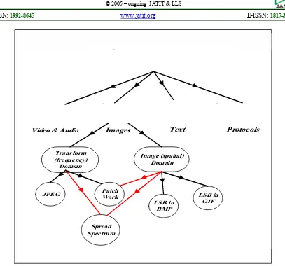
II. Transform (frequency) Domain: it is considered a complex technique for concealing messages inside the image, as it depends on the manipulation of the orthogonal transform of the image as opposed to the image itself, mostly handling the frequency content of the image. However, transformation or frequency domain conceals messages inside areas of the image, which are less exposed to compression, editing, cropping, and image processing. Some examples of the transform (frequency) domain are Discrete Fourier Transformation technique (DFT), Discrete Cosine Transformation technique (DCT), Discrete Wavelet Transformation technique (DWT), Lossless or Reversible method (DCT), and Embedding in coefficient bits [10]. Figure 3 demonstrate the spaces/branches of Steganographic systems. In this paper, a new technique is proposed to improve the data concealing capacity. The proposed technique plans to achieve limitless concealing capacity and disposes of the likelihood of the attackers to see any secret data inside the image. Thus, the proposed technique enhances both
Video & Audio Images Text Protocols
Transform (frequency)
Domain
Image (spatial) Domain
JPEG Patch
Work
LSB in BMP
LSB in GIF
[image:3.612.101.508.56.436.2]Spread Spectrum
1215 imperceptibility and security, since the proposed technique depends on exact matching between secret information and the image values. However, a Random Key–Dependent Data (RKDD) is created based on these matches. Furthermore, the result of the implemented test demonstrates that the proposed strategy has boundless concealing data, as well as this result shows the best imperceptibility comparing to the other Steganographic techniques. However, this paper is organized as follows: previous works are described in section 2, our proposed system is detailed in section 3, and experimental results are shown in section 4.
2. RELATED WORKS
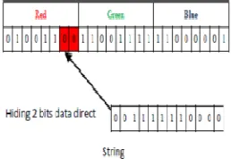
[image:4.612.311.543.174.359.2]Vyas and Pal introduce an improved LSB method [11] by finding the exact matching between the two least significant bits in image pixels values (red, green and blue) and the secret data. However, this technique hides two by two bits of the secret message in the identical locations according to the selected randomly pixel, as shown in Figure 4. As proposed in [11], if the identical locations are not found, then the two least significant bits should be hidden, and the image old values should also be replaced with new values. As well as, the locations of the hiding bits are saved in a binary table. Moreover, the experimental results show that this method keeps the original image quality as original after the embedding process.
Figure 4. Improved LSB Method [11]
Sharma and Kushwaha [12], proposed a dual transform method using Neural Network in Wavelet Transform Domain. However, both cover image and secret image are read. Neural networks are used in this method as classifiers in Wavelet Transform Domain applying fusion process, which may include arithmetic operations and logical
operations.. Figure 5. (a) Illustrates the embedding and Figure 5. (b) Illustrates extraction process. Test results show that this technique gains better robustness and imperceptibility against visual and statistical attacks.
Figure 5. (A). Embedding Process (Sharma and Kushwaha, 2015)
Figure 5. (B). Extraction Process (Sharma and Kushwaha, 2015)
[image:4.612.312.526.217.464.2] [image:4.612.145.274.502.591.2]1216 provides a high level of security and 50% capacity of the cover image. Five Modulus Method (FMM) is another method that is proposed by Jassim [15]. The neighboring pixels are correlated (this is a common characteristic in most grayscale images), which means that neighbors of the pixel tend to be similar to the original pixel (the idea behind FMM). While, each pixel is a number between 0 and 255. Keeping in mind that this transformation will not affect the Human Visual System (HVS). Dividing the image into (k) blocks and checking each (k) block pixels is a number dividable by 5. The values that are not divisible by 5 are distinct inside k block. The FMM method selects a window size for embedding process by Eq. 1.
Window size = √ (n/4) (1)
Where:
N is the number of characters in the secret text.
The number of values inside the (KxK) window is
k^2. Test results show that no noticeable dissimilarities between the stego-images with the original image. Hence, this is robust evidence that FMM method is not highly affected when the secret file size increased. In a research conducted by Dehare and Bonde [16], 75% of the secret message’s size is hidden inside the cover image using Five Modulus Method and the rest of the secret message is hidden inside the cover image by the LSB Substitution method. Thus, private stego-key for the extracting process is generated. Test results indicate a good image quality and low computational complexity. The method of hiding the secret messages based on Human Visual System (HVS) color space is proposed by Abdullah [17]. The color image is converted from RGB color space to Hue, Saturation, and Value. Hue component with values of 60, 120 and 180 used for hiding secret messages. In photomontage, the color space (HSV), is converted back to RGB. Test results demonstrate that the proposed method improves the imperceptibility. Using Zero Order Hold method (ZOH) for embedding a secret message inside another image is introduced by Abdelmgeid et al. [18]. The average of two adjacent pixels in the cover image is calculated. If the value is equivalent to the value of the bit of secret message, the bits will not be changed or modified. Otherwise, the values of the bits are changed to match the secret image bits values. ZOH method has been tested using different cover image sizes. The test results show that ZOH has higher PSNR values than the LSB. The LSB and Set Partitioning
in Hierarchical Trees (SPIHT) based compression. A method presented by Thenmozhi and Menakadevi [19].The method first compresses the message image by using the SPIHT algorithm. The compressed data is embedded into the cover image using the LSB technique. In the receiver side, first, the data is decoded using the LSB method and then it is decompressed using the SPIHT algorithm. An inverse wavelet transform is applied to recover the original secret image. High Capacity Image Steganography Technique based on LSB Substitution method in [20]. This method divides the image into two parts and works only on grayscale images. The first part used for embedding where some pixels bits values changed based on the secret message using LSB substitution technique, the second part used to show the changes applied to the first part. The cover image combined back again to get the stego-image. Extraction process compares the original image with the stego-image and finds the modified pixels, meaning that, the original image must be known to the receiver side. The method was tested using different images sizes achieving a better image quality and high embedding capacity, the main disadvantage of this method that the receiver must know the original image and the image which make the stego-image suspected by hackers due to the differences between both original and stego-image.
3. PROPOSED METHOD
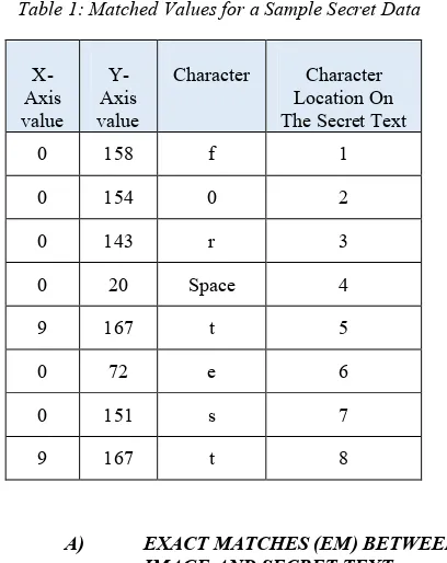
1217 Table 1: Matched Values for a Sample Secret Data
A) EXACT MATCHES (EM) BETWEEN
IMAGE AND SECRET TEXT
This section briefly describes the technique of finding the matches between the image and the secret text. It starts with reading the selected image Blue channel values (B), as decimal values. Then the secret text is converted to decimal ASCII representation. The brute force is applied to discover the matches between the image Blue channel pixels values and the secret text. In the middle of the searching process, each matched character will be excluded from the seeking values and skipped to the following character. The technique will not regenerate the location(s) of any character(s) that is repeated in the secret text for (n) times and takes only one match from the image Blue channel pixels values. After finding the last character, all coordinated locations (x, y) for the blue channel pixels values and the locations of the characters of the secret text will be stored. Table 1 demonstrates a sample for a secret text which has been searched in a selected image. The secret text is "for test". Notice that the character (t) is repeated twice in the secret text, in locations 5 & 8.In this case, the system selects the first matched (Blue) value and store it.
The pseudo code below shows how the proposed system functions for searching and selecting the matches between the secret text and the image
I. Start.
II. Input: The image and the secret data.
III. Output: A list of Matched Pixels locations (x, y) and character’s locations in the secret text.
IV. Read: The image blue pixel values (decimal values) and convert the secret data to ASCII code (decimal). Store these values into 2 strings, Str1and Str2 respectively.
V. Start Searching: For the exact matches between the image and secret data. Store the matched pixels location (x, y) in the image and its location on the secret data. VI. Randomly Select: One match from the
image values which represents a character in the secret data and stores these values in a list.
VII. End.
B) RANDOM KEY –DEPENDENT DATA
(RKDD) FORMULATION PROCESS
The key generation process and size are very important issues that should be addressed. However, a new approach is used to formulate the key depending on the secret data and the matched pixels in the image. Each image is a two-dimensional array which has an x-axis (row) value and y- axis (column) value. These values are numbers (integers) from 0 to 9. In the secret text, each character has a location in the text that can be represented as an array. The array index is the location of the character on the secret text. Meanwhile, the key must hold three values for each character. The first value is the matched pixel location(x, y). The second value is the character location on the secret text. The third value is a special character ($) used to separate x-axis and y-axis of the pixel location. The (-) character will be used to represent the space between words in the secret data. The (^) character is used to separate between characters location in the text. Moreover, the proposed system randomly selects only one location for the repeated character in the secret text to reduce the key size. Accordingly, we can determine how the proposed system can formulate the key depending on the data. First of all, each integer from (0 to 9) will be represented as four-bit binary number as demonstrated in Table 2. This approach helps us to reduce the size of each character from 8 bits to 4 bits.
X-Axis value
Y- Axis value
Character Character Location On The Secret Text
0 158 f 1
0 154 0 2
0 143 r 3
0 20 Space 4
9 167 t 5
0 72 e 6
0 151 s 7
1218 Table 2: The Generated Four Bits to Represent
Key Components
Number/Symbol 4-bit Binary Value
0 0000
1 0001
2 0010
3 0011
4 0100
5 0101
6 0110
7 0111
8 1000
9 1001
$ 1010
^ 1100
- 1011
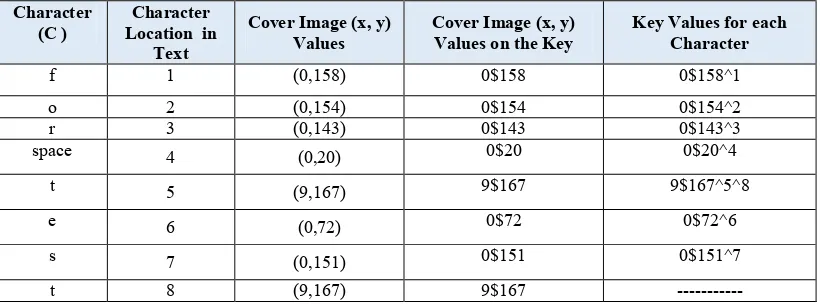
However, to complete the key formulation process, an important step is required. The proposed system demonstrates the structure of the key and the hold data. Since, Table 3, shows a working example for key dependent generation process with a secret text “for test“. Furthermore, tracing the text example and generating the key were presented as below:
• The first character (f): is addressed on the image as (0,158) respectively as (x, y), hence the key generation process uses this value by separating x and y by using the symbol ($) and produces the value (0$158). Actually, this value is considered as the first part of the key value.
• The next character (o) is found on (0,154) in the image, whereby, the second part of the key value is (0$154).
• Character (r): is located on (0,143) in the image, whereby the value (0$143) is processed.
• Character (Space): is located on (0, 20) in the image, whereby the key generated value is (0$20).
• Character (t): is located on (9,167), whereby the key generated value (9$167). • Character ‘e ' is located on (0, 72) in the
image, the key generated value is (0$72). • Character (s): is located on (0,151) in the
image, whereby the key generated value is (0$151).
• Finally, character (t): is located on (9,167) in the image, the key generated values are (9$167).
Notice that: as in the example text, the character (t) is repeated, and the proposed system will not use this duplication by generating two different values on the key. Therefore, the system will add (^8) to the index for the first (t). Figure 6 shows the overall key value for this example.
Figure 6. Key Complete Value for a Sample Text
[image:7.612.86.496.365.517.2]With the total value of 220 bits (27.5byte), we should keep in mind that the key length will be depended on the number of characters of the secret text.
Table 3: The Structure of the Key and All Data that theKey Holds
Character (C )
Character Location in
Text
Cover Image (x, y) Values
Cover Image (x, y) Values on the Key
Key Values for each Character
f 1 (0,158) 0$158 0$158^1
o 2 (0,154) 0$154 0$154^2
r 3 (0,143) 0$143 0$143^3
space 4 (0,20) 0$20 0$20^4
t 5 (9,167) 9$167 9$167^5^8
e 6 (0,72) 0$72 0$72^6
s 7 (0,151) 0$151 0$151^7
t 8 (9,167) 9$167 ---
1219
C) RKDD EXTRACTING AND SECRET
TEXT BUILDING PROCEDURE
The extraction process should be successfully done based on the key. The same image, which has been selected as the cover image (by the sender), must be taken as the input image for the extraction process, (by the receiver). However, the proposed system starts the extraction process by decoding the Random Key-Dependent Data (RKDD). Key decoding process starts by reading each single element of the key. However, the key decoding process is discussed below:
• The first element is (0), which represents the first character in x-axis value.
• The next element (s), which is used to separate between x-axis value and y-axis value. The system will discard this element and move to the next value. • The next value is (158), which represents
y-axis value. Now first character (x, y) value is decoded from the image as located in (0, 158) and produces the character (f). • The character location on the secret text should be determined. As explained in Section 3.2, the character (^) is used to separate between the character (x, y) value and its location on the secret text. The next element after (x, y) is (^) which shows that the next value is the character location on the secret text. In this system, character (^) is discarded.
• The system will keep going decoding the key until no more values are to be decoded in the key.
One important thing that should be pointed out, the character (t) is shown in two locations in the secret text, locations (5 & 8) and represented in the key as (9$167^5^8). Therefore, the system will start decoding the first value to be x-axis value discarding (s), followed by y-axis value to be (167). The (^) indicates that the followed value will be the 5th character location, and the followed value will be the 8th character location. After decoding the whole key elements, the system moves directly to the image (x, y) values listed on the key and converts them to ASCII code in order to build the secret text. The pseudo code below shows how the proposed system decodes the key process and recovers the secret text.
I. Start.
II. Input: Original the image as Stego-image. III. Output: Secret data.
IV. Decode: The key to get the location of the matched values.
V. Read: The image to find the locations(x, y).
VI. Convert: The values in these locations from decimal to ASCII.
VII. Build: The secret message.
VIII. End.
1220 Figure 7. The Proposed System-Block Diagram
4. EXPERIMENTS RESULTS AND ANALYSIS
In this section, experimental results are introduced to verify the proposed system against Steganographic systems features. Embedding capacity, invisibility and the quality of the Stego images. Finally, robustness and security. Moreover, the test includes the searching time, key Stego-key size and a comparison between the proposed systems with some existing systems. To conduct these experiments, a common images used in image
processing as a cover images. These images are airplane, mandrill, woman dark hair, Elaine, Lena, and peppers, as shown in Figure 8.
Airplane Mandrill Woman
dark hair
Lena Peppers
Figure. 8 : Images Used to Test the Proposed System
The test starts by analysis the embedding capacity for the proposed system. The test conducted using Lena picture as cover image and secret text compose of (902) characters. The test results prove that the proposed system can find at least one match for each character as shown in Figure 9. Form the test results it’s clear that the character (c) more than (364) match in the cover image, while characters (p and n) has lowest matches in the image.
The cover image quality and invisibility are both related to each other. If the quality of the cover image changed after embedding process then any attacker can visually or statically distinguish the difference between the image before and after word embedding. The Stego-image quality is measured by the MSE and PSNR. The PSNR is defined as Equation (2):
PSNR=10×log10 (255) ^2/ MSE) (2)
Where the MSE (mean square error) is defined as Equation (3).
(3)
[image:9.612.330.524.168.346.2]1221
Where:
The row and the column pixel in the original (cover) image.
The row and the column pixel in the stego-image.
M and N are the height and the width of the image.
From Eq. (3), the MSE is the difference between the cover image pixels values and the Stego-image pixels values. The proposed system keeps the cover image pixels values untouched or modified which impels that the MSE value is zero. The best quality of an image achieved when the MSE value is zero or approach to zero. Moreover, the PSNR value must be as high as possible. The PSNR value for the Stego-image produced by the proposed system is infinite, and is the best among all existing systems.
Using a Stego-key that is randomly generated based on the matched RGB values and the secret text enhance the proposed system security. Moreover, the Stego-key reinforces the proposed system security and robustness against attacks and secret message extraction.
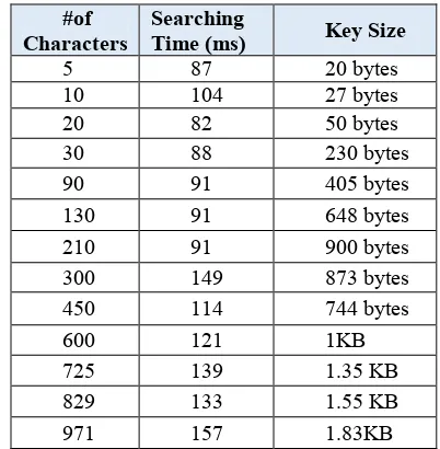
[image:10.612.92.519.65.286.2]The test results which are clear in Table 4 indicate a reasonable searching time and key size. Repeating the characters will reduce the key size since. In our system, only the location of the repeated character will be represented on the key as stated in Section 3.2. The relationship between the key size (KB) and the number of matches is demonstrated in Figure 11.
Table 4. Key Size with Different Secret Message Sizes
Basically, the Stego-key size will reduced by applying any compression technique, such as Huffman compression method. After converting the Stego-key into binary. The proposed system tested using several secret messages sizes and different cover images sizes.
#of Characters
Searching
Time (ms) Key Size
5 87 20 bytes
10 104 27 bytes
20 82 50 bytes
30 88 230 bytes
90 91 405 bytes
130 91 648 bytes
210 91 900 bytes
300 149 873 bytes
450 114 744 bytes
600 121 1KB
725 139 1.35 KB
829 133 1.55 KB
[image:10.612.328.529.449.654.2]971 157 1.83KB
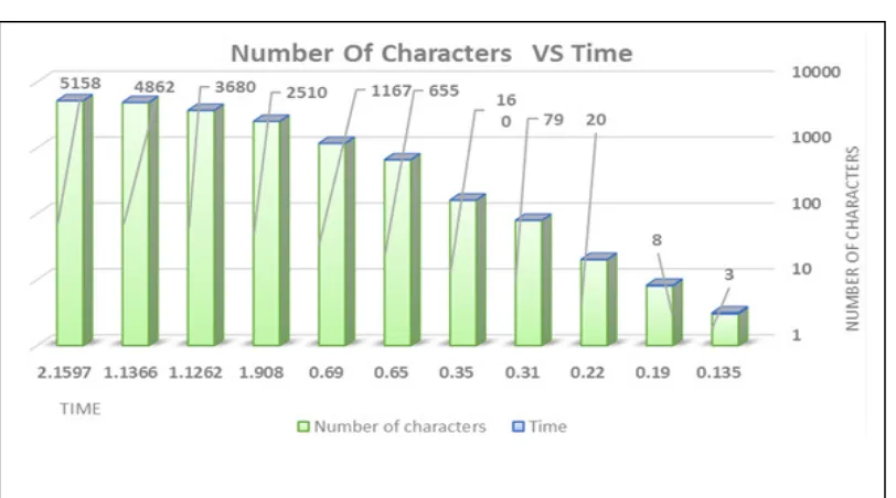
1222 The experiments’ outputs based on searching time is demonstrate in Figure 10. It indicates a very high speed in finding matches for the secret text inside the cover images. The proposed system characterized by requiring low computational power and low memory, so it is easy to test it or use it in any PC available.
[image:11.612.115.521.114.340.2]As we used in our system brute force algorithm in finding the matches between the secret text and the cover images’ pixels values. The brute force algorithm does not require any pre-processing phase and constant extra space.
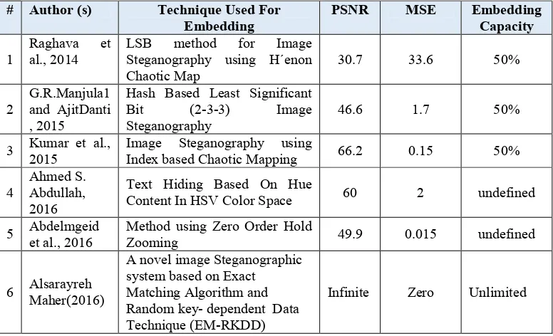
[image:11.612.118.528.382.592.2]1223 Searching time and key-size will not be included in the comparison because the proposed system uses a new approach for finding the matches between the secret text and the cover image. Also the Stego-key generation is novel, where none of the existing system uses the same approach to compare with. Table 6 demonstrates the comparison between the proposed method and other Steganographic systems.
We build a comparative study between our proposed system and other existing systems. The evaluation criteria is based on PSNR, MSE values and embedding capacity.
5. CONCLUSION
In this work, we present a novel system to hide secret messages/data inside the image. This work finds the exact matches between the image RGB decimal values and the secret message/data after converting them to ASCII. However, the system generates a key to recover the secret data which is randomly generated based on matched pixels and the secret text. As presented in the investigation outcomes, the proposed system is more efficient than the existing systems in many features such as PSNR, MSE, invisibility and security.
In terms of the invisibility, the proposed system is considered to be invisible, since the
cover-mage is untouched to be noticed by attackers and hackers. Security and robustness are mainly related to the invisibility feature. If a secret message is being unseen, then it will not be attacked. In addition, the randomly generated Stego-key will protected the secret message.
Finally, the proposed system is compared with other existing Steganography systems. The testing results are considered to be extremely encouraging, and we introduce a new approach that has never been used by any existing Steganography systems. Furthermore, the security of the proposed system is enhanced. The proposed system can be used in many applications such as security agencies, military, IOT, and other interested parties.
REFERENCES:
[1] Mahesh Kumar and Munesh Yadav, “Image Steganography Using Frequency Domain”, International Journal of Scientific & Technology Research, Volume 3, Issue 9, (2014), ISSN 2277-8616, pp: 226-230.
[2] G.R.Manjula1 and AjitDanti, “A Novel Hash Based Least Significant Bit (2-3-3) Image Steganography in Spatial Domain”, International Journal of Security, Privacy and Trust Management (IJSPTM) Vol 4, No 1,
(2015), pp: 226-230. DOI:
[image:12.612.140.528.130.366.2]10.5121/ijsptm.2015.4102.
Table 5. The Comparison between the Proposed Method and Existing Steganography Systems
# Author (s) Technique Used For Embedding
PSNR MSE Embedding
Capacity
1
Raghava et al., 2014
LSB method for Image Steganography using H´enon
Chaotic Map 30.7 33.6 50%
2 G.R.Manjula1 and AjitDanti , 2015
Hash Based Least Significant
Bit (2-3-3) Image
Steganography 46.6 1.7 50%
3 Kumar et al., 2015 Image Steganography using Index based Chaotic Mapping 66.2 0.15 50%
4 Ahmed S. Abdullah, 2016
Text Hiding Based On Hue
Content In HSV Color Space 60 2 undefined
5 Abdelmgeid et al., 2016 Method using Zero Order Hold Zooming 49.9 0.015 undefined
6 Alsarayreh Maher(2016)
A novel image Steganographic system based on Exact Matching Algorithm and Random key- dependent Data Technique (EM-RKDD)
1224 [3] T. Morke, J.H.P. Eloff and M.S. Olivier, “An
Overview of Image Steganography”. Information and Computer Security Architecture (ICSA) Research Group, Department of Computer Science, University of Pretoria, Pretoria, South Africa,(2003) http://repository.rootme.org/St%C3%A9ganog raphie/EN%20%20Image%20Steganography% 20Overview.
[4] Randeepika Samagh and Shailja Rani, “Data Hiding using Image Steganography”, International Journal of Emerging Trends in Engineering and Development, Issue 5, Vol. 3, (2015), ISSN 2249-6149, pp: 123-124.
[5] Megha Goyal, Yashpal Lather and Vivek Lather, “Analytical Relation & Comparison of Psnr and Ssim on Babbon Image and Human Eye Perception Using Matlab”, International Journal of Advanced Research in Engineering and Applied Sciences, Vol. 4, No. 5, May 2015, ISSN: 2278-6252
[6] Shreenandan Kumar, Suman Kumari and Sucheta Patro, “Image Steganography using Index based Chaotic Mapping”. International Conference on Distributed Computing and Internet Technology, (2015), (ICDCIT-2015). [7] Ms.G.S.Sravanthi, Mrs.B.Sunitha and Devi,
S.M.Riyazoddin, “A Spatial Domain Image Steganography Technique Based on Plane Bit Substitution Method”. Global Journal of Computer Science and Technology Graphics & Vision, (2012), Online ISSN: 0975-4172 & Print ISSN: 0975-4350.
[8] Richa Gupta, Sunny Gupta and Anuradha Singhal, “Importance and Techniques of Information Hiding: A Review”, (2014), International Journal of Computer Trends and Technology.
[9] Mehdi Hussain and Mureed Hussain, “Survey of Image Steganography Techniques”, International Journal of Advanced Science and Technology, Vol. 54, May, (2013).
[10] Sudhanshi Sharma and Umesh Kumar, “Review of Transform Domain Techniques for Image Steganography”, International Journal of Science and Research, Volume 4 Issue 5, May (2015), pp: 194-197.
[11] Krati vyas and B.L.Pal,” A Proposed Method in Image Steganography to Improve Image Quality with LSB Technique”, International Journal of Advanced Research in Computer and Communication Engineering, Vol. 3, Issue 1, January (2014), pp: 5246-5251.
[12] Anamika Sharma and Ajay Kushwaha,”Image Steganography Scheme Using Neural Network in Wavelet Transform Domain”, International Journal of Scientific Engineering and Research, (2015).
[13] N. S. Raghava, Ashish Kumar, Aishwarya Deep an AbhilashaChahal, “Improved LSB method for Image Steganography using H´enon Chaotic Map”, Open Journal of Information Security and Applications, Volume 1, Number 1, (2014), pp.: 34-42. [14] Haoran Wen, “A review of the H´enon map and
its physical interpretations”, School of Physics Georgia Institute of Technology, Atlanta, GA 30332-0430, U.S.A, (2014).
http://chaosbook.org/projects/Wen14.pdf. (Accessed on July 30, 2016).
[15] Firas A. Jassim, “A Novel Steganography Algorithm for Hiding Text in Image using Five Modulus Method “, International Journal of Computer Applications (0975 – 8887), (2013). Volume 72– No.17, June 2013, pp: 39-44. [16] Praneeta Dehare and Padma Bonde,”Hiding
Image in Image by using FMM with LSB Substitution in Image Steganography”, International Journal of Advance Research in Computer Science and Management Studies, (2014). Volume 2, Issue 11, November 2014, pp: 455-458.
[17] Ahmed S. Abdullah, “Text Hiding Based On Hue Content In HSV Color Space”, International Journal of Emerging Trends & Technology in Computer Science, Volume 4, Issue 2, March-April (2015), ISSN 2278-6856, pp: 170-173.
[18] Abdelmgeid A. A. , Tarek A. A. , Al-Hussien Seddik, Saad and Shaimaa M. H., “New Image Steganography Method using Zero Order Hold Zooming”, International Journal of Computer Applications (0975 – 8887), Volume 133 – No.9, January (2016), pp: 27-31.
[19] M.J.Thenmozhi, Dr.T.Menakadevi, A New Secure Image Steganography Using LSB and Spiht Based Compression Method, International Journal of Engineering Research & Science (IJOER), and ISSN: 2395-6992, Vol-2, Issue-3 March- 2016, and pp.: 80-85. [20] Marghny H. Mohamed and Loay M. Mohamed,