Technology (IJRASET)
Comparative Analysis of Different Methods of
Tuning Load Frequency Control Problem
Ashif khan1, Rameshwar singh2, Rekha kushwah3
1
M.Tech Student, 2Assistant professor, 3Assistant professor
1,2
Department of Electrical Engineering, NITM Gwalior, RGPV
Abstract— This paper studies control of load frequency in single area power systems with Ziegler-Nicholas PID controller. In this study, Ziegler-Nicholas PID controller is used to determine the parameters of the Ziegler-Nicholas PID controller according to the system dynamics. The proposed Ziegler-Nicholas PID controller has been compared with the conventional integral controllers. The settling times and peak amplitude with the proposed Ziegler-Nicholas PID controller are superior to the outputs of the same characteristics of the conventional integral controllers. The Time-domain simulations using MATALB SIMULINK has been performed to demonstrate the effectiveness of the proposed Ziegler-Nicholas PID.
Keywords— Load Frequency Control (LFC), Integral Controller, Ziegler-Nicholas, PID controller, single area
I. INTRODUCTION
In recent years electricity has been used to power more sophisticated and technically complex manufacturing processes, and a variety of high-technology consumer goods. These products and process are sensitive not only to the continuity of power supply but also on the quality of power supply such as voltage and frequency. In power system, both active and reactive power demands are never steady they continuously change with the rising or falling trend. The changes in real power affect the system frequency, while reactive power is less sensitive to changes in frequency and is mainly dependent on Changes in voltage magnitude [1]. Normal operating conditions to remain stable operating condition and after exposure makes it possible to attain an acceptable feature of re-equilibrium state .In a sudden change in consumers' demands for power, voltage and frequency control a complicating factor. Power systems have the desired level of tension, is desirable to have a fixed rate. At this point, the power system load frequency control, it is important for stability. Load frequency control with voltage and frequency of the system is set. Therefore, the system will be increased power quality [2-3], Load frequency control in power systems is very important in order to supply reliable electric power with good quality. The goal of the LFC is to maintain zero steady state errors in a single area power system. In addition, the power system should full the proposed dispatch conditions. All generators are supposed to constitute a coherent group in each control area. From the experiments on the power system, it can be seen that each area needs its system frequency to be controlled. In this study, a single area power system is load frequency control of this system is simulink by a Ziegler-Nicholas PID controller and a conventional integral controller.
II. LOADFREQUENCYCONTROLOFSINGLEAREASYSTEM
The aim of LFC is to maintain real power balance in the system through control of system frequency. Whenever the real power demand changes, a frequency change occurs. This frequency error is amplified, mixed and changed to a command signal which is sent to turbine governor. The governor operates to restore the balance between the input and output by changing the turbine output. This method is also referred as Megawatt frequency or Power frequency (P-f) control [4]. For the satisfactory operation of power system the frequency should be maintained constant. The considerable drop in frequency in any electrical network could result in high magnetizing currents in induction motors and transformers [5]. So it is essential to regulate the frequency which is a common factor throughout the system. Moreover, the change in active power depends on frequency deviations and hence, the change in frequency in any point of the interconnected power system may affect the active power throughout the system. As a consequence the LFC is installed in power network to meet out the following objectives.
Maintain the frequency to its nominal value Maintain optimal power flow between control areas
Maintain economic power generation in individual generating units
Technology (IJRASET)
[image:3.612.156.453.175.353.2]The real power control mechanism of a generator is shown in Fig. 1. The main parts are: 1) Speed changer 2) Speed governor 3) Hydraulic amplifier 4) Control valve. They are connected by linkage mechanism. Their incremental movements are in vertical direction. In reality these movements are measured in millimetres; but in our analysis we shall rather express them as power increments expressed in MW or p.u. MW as the case may be. The movements are assumed positive in the directions of arrows. Corresponding to “raise” command, linkage movements will be: “A” moves downwards; “C” moves upwards; “D” moves upwards; “E” moves downwards. This allows more steam or water flow into the turbine resulting incremental increase in generator output power. When the speed drops, linkage point “B” moves upwards and again generator output power will increase [6].
Fig 1 diagram of real power control mechanism of a generator [6]
IV.MODELLINGOFSINGLEAREASYSTEMLOADFREQUENCYCONTROL(LFC)
An isolated electric area, where one generating unit or bunch of generating units, is placed in close vicinity to distribute the electricity in the same area is called single area system. More than one control area power systems with a single control zone is actually a combination of power systems and the problems of each region, combining a control structure. Figure 1 is a single zone with a power system block diagrams fig 2. Here, the system, a regulator regulating the speed of synchronous generator, synchronous generator and the load is composed [7]. Only the generating unit present in that area is responsible to maintain the desired frequency in normal and abnormal conditions.
Fig 2. Single-zone power system block diagram [7].
For LFC scheme of single generating unit has basically three parts Generator and load
[image:3.612.118.496.485.659.2]Technology (IJRASET)
Turbine
In the next section, mathematical transfer function model of single area thermal system is developed
V. INTEGRALCONTROLLERFORLOADFREQUENCYCONTROL
PI controllers are very often used in industry, especially when speed of the response is not an issue Among various types of load frequency controller, the PI controller are most widely used to speed-governing system for LFC scheme [8]. The proportional plus integral controller (PI controller) produces an output signal consisting of two terms-one proportional to error signal and the other proportional to the integral of error signal An advantage of the PI control technique is to reduce the steady-state error to zero by feeding the errors in the past forward to the plant .P-I controller is mainly used to eliminate the steady state error resulting from P controller. However, in terms of the speed of the response and overall stability of the system, it has a negative impact. This controller is mostly used in areas where speed of the system is not an issue. Since P-I controller has no ability to predict the future errors of the system it cannot decrease the rise time and eliminate the oscillations. If applied, any amount of I guarantees set point overshoot [9]. PI controller will eliminate oscillations and steady state error resulting in operation of on-off controller and P controller respectively.
VI.TECHNIQUEOFZIEGLER-NICHOLSTUNINGMETHOD
Ziegler method is based on an open-loop step response test of the process, hence requiring the process to be stable. The unit step response of the process is characterized by two parameters, L and T. The frequency response method is also based on describing the process with two parameters that are the crossover gain, Kc, and the crossover period, Tc. For determining these parameters, the plant is controlled with a P-controller, and its gain is increased until the system oscillates critically [10].A very useful empirical tuning formula was proposed by Ziegler and Nichols in early 1942. The tuning formula is obtained when the plant model is given by a first-order plus dead time which can be expressed by The Ziegler-Nichols step response and frequency response methods are the classical tuning methods for PID controllers [11].
VII. MATLABSIMULINKRESULTS
[image:4.612.88.517.563.707.2]The simulation has been conducted in MATLAB (R2012a) for single area power system with Integral and Ziegler-Nicholas PID tuning controller is design for Power plant model using MATLAB Simulink. The frequency deviations in Power area studied under PI controller and Ziegler-Nicholas PID. The common nominal system parameters quoted in most of the references [12] are used in this paper. They are show in the table 1
Table 1 nominal system parameters [12]
Governor gain Governor time
constant
Turbine gain Turbine Time
Constant
Generator load Generator
constant
1 0.08 1 0.3 120 20
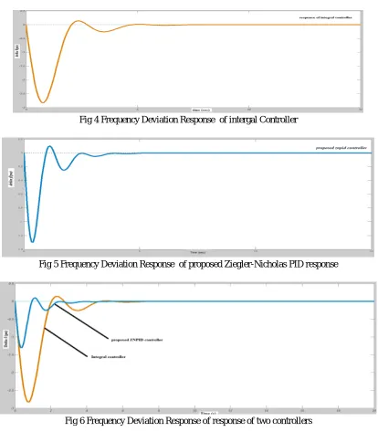
The models of single area Integral and Ziegler-Nicholas PID show in the fig 3 the resulting graph integral controller fig 4 ,Ziegler-Nicholas PID fig 5 and combined are given in Fig 6 .simulated in SIMULINK.
Technology (IJRASET)
Fig 4 Frequency Deviation Response of intergal Controller
Fig 5 Frequency Deviation Response of proposed Ziegler-Nicholas PID response
Fig 6 Frequency Deviation Response of response of two controllers
VIII. CONCLUSION
It has been shown that the proposed control algorithm is effective and provides significant improvement in system performance both in the transient and steady state responses. Reduce the settling time and peak amplitude, its clear the fig 6 Therefore, the proposed Ziegler-Nicholas PID controller is recommended to generate a good quality and reliable electric energy..
REFERENCES
[1] T R Shyama, R Satheesh Kumar, V Shanmugasundaram, “Design of FGSPI Controller Based Combined LFC and AVR of Two Area Interconnected Power Generating System” International Journal of Engineering and Advanced Technology (IJEAT) ISSN: 2249 – 8958, Volume-1, Issue-4, April 2012
[2] Hilmi Zenk, Osman Zenk, “Two Different Power Control System Load- Frequency Analysis Using Fuzzy Logic Controller”IEEE 2011.
[3] S. Zhang, C. Zhu, J. K. O. Sin, and P. K. T. Mok, “A novel ultrathin elevated channel low-temperature poly-Si TFT,” IEEE Electron Device Lett., vol. 20, pp. 569–571, Nov. 1999.
[4] A. Soundarrajan1, S. Sumathi2 and G.Sivamurugan3, “Hybrid Evolutionary Algorithms for Frequency and Voltage Control in Power Generating System”, international Journal on Soft Computing, October 2010, issue 02.
Technology (IJRASET)
International Conference on Innovations in Engineering and Technology (ICIET’14), Volume 3, Special Issue 3, March 2014. [6] Hadi saadat, eds 1999. “Power System Analysis”, Mcgraw-Hill International edition, 2005.
[7] Hilmi Zenk, Osman Zenk, Adem Sefa Akpinar, “Two Different Power Control System Load- Frequency Analysis Using Fuzzy Logic Controller”IEEE 2011. [8] D.M. Vinod Kumar, “Intelligent Controllers for Automatic Generation Control”, IEEE Transactions on global connectivity in energy, computer,
communication and control, 1988, pp557-574.
[9] Atul Ikhe, Anant Kulkarni, “Load frequency control for interconnected power system using different controllers” Automation, Control and Intelligent Systems 2013; 1(4): 85-89.
[10] Siraj Anjum1, Kapil Parikh2, Raunak Jangid3, “Evaluating the Feasibility of Load Frequency Control in Automatic Generation Control using Particle Swarm Optimization Technique” International Journal of Scientific Research Engineering & Technology (IJSRET), ISSN 2278 – 0882 Volume 3, Issue 5, August 2014.
[11] N.EL.Y. Kouba, M. Menaa, M. Hasni, B. Boussahoua, and M. Boudour, “Automatic Generation Control in Interconnected Power System with Integration of Wind Power Generation Using PID Controller Based on Particle Swarm Optimization”, International Conference on Renewable Energies and Power Quality (ICREPQ’14), ISSN 2172-038 X, No.12, April 2014.
![Fig 2. Single-zone power system block diagram [7].](https://thumb-us.123doks.com/thumbv2/123dok_us/8582899.861464/3.612.156.453.175.353/fig-single-zone-power-system-block-diagram.webp)
![Table 1 nominal system parameters [12] Turbine gain Turbine Time](https://thumb-us.123doks.com/thumbv2/123dok_us/8582899.861464/4.612.88.517.563.707/table-nominal-system-parameters-turbine-gain-turbine-time.webp)