Effects of Process Parameters on the
Microstructural Properties of MIG and FSW Joints
K. Palani1, C. Elanchezhian2, B. Vijaya Ramnath3, G. B. Bhaskar4, J. Sai Jagadeesh5, G. Manoj Kumar6
1
Assistant Professor, Dept. of Mechanical Engineering, SCSVMV University, Kanchipuram-631 561, India 2
Professor, Dept. of Mechanical Engineering, Sri Sairam Engineering College, Chennai-600 044, India 3
Associate Professor, Dept. of Production Technology, MIT Campus, Anna University, Chennai-600 044, India 4
Student, Dept. of Mechanical Engineering, SCSVMV University, Kanchipuram-631 561, India
Abstract: The present research work is undergone to investigate the effect of weld parameters on the microstructural behavior of metal inert gas welding (MIG) and friction stir welding (FSW) joints. The selection of process parameters is important in the welding process to produce the best quality of welded joints. The process parameters of nozzle to plate distance, torch angle and Arc voltage for metal inert gas welding and rotational speed, tool tilt angle and Feed rate for friction stir welding processes are considered. The microstructural study is carried out on the welded joints using scanning electron microscope and the microstructure of friction stir welding process gives the better and defect free welded joints compared to microstructures of Metal inert gas welding process.
Keywords: Aluminium alloy; Titanium alloy; Process parameters; Microstructure; Metal inert gas welding; Friction stir welding.
I.INTRODUCTION
Aluminium alloys and titanium alloys are widely used in various industrial applications such as aerospace, automotive, marine industries because of its properties of low weight, corrosion resistance and suitable for all fusion welding processes. Nowadays the dissimilar welding is important to make material joining. The fusion welding is mainly considered for dissimilar materials joining effectively due to the variations of melting temperature of the materials. Metal Inert Gas (MIG) welding is done by using Argon or Helium as a shielding gas and consumable electrode as a conductor and also it is versatile, gives very little loss of alloying elements. The high power density of plasma arc welding is becoming prominent to exhibit quick fusion between metals. Even though this fusion welding of dissimilar weldments is weak in the transition region and it has fumes, crack and spatter and this will be overcome by the solid state welding process. Friction stir welding is the new and innovative method to make similar and dissimilar joints effectively. Some important information has been gathered from the following literatures for the dissimilar welded joints. The investigations are made on the tensile and impact strength of GTAW and FSW joints of interstitial free steel and the higher tensile and impact strength of FSW joints are unveiled and enrichment in strength and toughness are 24 % and 39% respectively by comparing the GTAW process [1].
The study is made on tensile properties and fracture location of the FSW joints and the presence of micro-voids are important in the NZ with the heat input of RP greater than around 0.333 mm/rev. The fracture is happening in the HAZ for low RP which gives the weakest region in the welded joint while the RP increases or the heat input decreases, the fracture appears in the weld centre [7]. The investigation showed that the optimum FSW process parameters of tool rotational speed of 1400 RPM, welding speed of 60 mm/min, axial force of 8 kN yielded higher tensile strength properties compared to other joints and also found the defect free fine grained microstructure occur at the weld nugget zone [8].
Table 1. Mechanical properties of AA8011 Aluminium Alloy and Titanium alloy Grade 9
Base Metal
Mechanical Properties Chemical Composition (Wt.%)
Tensil e Strengt h (Mpa) Densit y (kg/m 3 ) Thermal Conductivi ty
(W/moK)
Meltin g Point
(oC)
Si Fe Mn Mg Ti Al C H V Zn Cr
AA80
11 110 2689 237
660. 3
0.1 4
- - - Re
m
2.8 0.0
4 0.01 6 2. 6 - - Ti alloy (Grd 9)
690 4480 8.3 1668
0.5 1 0.7 3 0.4 5 0.2 7 0.0 3 Re m
- - - 0.0
9 0.0
4
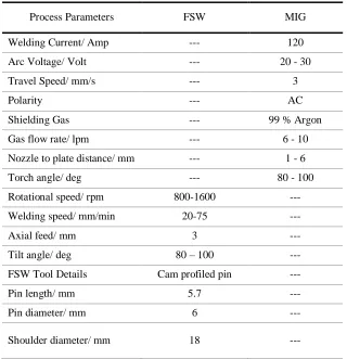
Table 2. Welding conditions and process parameters
Process Parameters FSW MIG
Welding Current/ Amp --- 120
Arc Voltage/ Volt --- 20 - 30
Travel Speed/ mm/s --- 3
Polarity --- AC
Shielding Gas --- 99 % Argon
Gas flow rate/ lpm --- 6 - 10
Nozzle to plate distance/ mm --- 1 - 6
Torch angle/ deg --- 80 - 100
Rotational speed/ rpm 800-1600 ---
Welding speed/ mm/min 20-75 ---
Axial feed/ mm 3 ---
Tilt angle/ deg 80 – 100 ---
FSW Tool Details Cam profiled pin ---
Pin length/ mm 5.7 ---
Pin diameter/ mm 6 ---
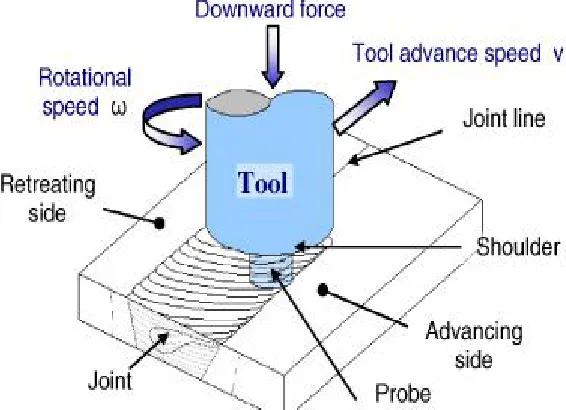
[image:3.612.147.467.401.732.2]The increase in rotating speed leads to increase the strain rate and for a constant traverse speed, lower rotating speed leads to lower strain rates [9]. When the rotating speed is kept constant, defect-free welds are obtained while at constant traverse speed, the groove-like defect is occurring. The welding speed of FSW affects the tensile strength of the joint and found that by increasing the travel speed, the increase in tensile strength of the Ti and Al alloy joints and at the mixed regions of the Ti alloy and Al alloy, the intermetallic compound are formed which affects the tensile strength joints [10]. In this investigation, comparative study of effects of process parameters on microstructural behavior between MIG and FSW joints are considered.
Fig. 1 Schematic diagram of Friction stir welding Process
II.MATERIALSANDMETHODS
A.Selection of Work Piece Materials
The AA 8011 aluminium alloy and Titanium alloy (grade 9) plates with a thickness of 6 mm are used for metal inert gas welding and similar aluminium alloy plates are considered for the friction stir welding shown in Fig. 1. The mechanical properties and chemical compositions of both materials are listed in Table 1. The surfaces of both plates are properly dressed with a steel brush and acetone before welding process. All welds are made in butt joint configuration.
B.Selection of Welding process and process parameters
In MIG, the workplace setup with workpiece properly covered and shielded with helium gases, which is used to protect the oxidation in titanium alloy plates. The process parameters of the MIG and FSW are listed in Table 2. In MIG, the EN4043 aluminium filler material is used to join the two different materials, while in FSW the Cam profiled HC-HCr steel which is used to produce proper joints using a Universal milling machine. The microstructural analysis are applied on the samples using standard metallographic procedures with the standard dimensions of 16 mm x 6 mm x 6 mm, with fine polishing using diamond paste of 0.5 μm particle sizes and the samples are etched using Keller’s solution which reveal the good microstructure of the weldments. The microstructural analysis is performed using Scanning electron microscope at weld centre.
III.RESULTSANDDISCUSSIONS
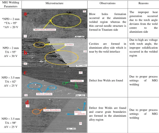
A.Microstructural analysis of dissimilar mig welded joints at the weld centre
torch angle from the weld centre is presented in Figs. 2 c-d. The grains formation in the welded region of the dissimilar MIG welding mainly depends upon the proper process settings with proper selection of electrode material. The MIG welding process parameters in the range of 3 to 4 mm nozzle to plate distance, 7 to 8 deviation from the weld centre with the 25V arc voltage are observed to produce the defect free welds by examining the microstructures of the welded joints.
MIG Welding Parameters
Microstructure Observations Reasons
*NPD = 2 mm
*TA = 95
*AV = 20 V
Blow holes formation
occurred at the aluminium welded region whereas the thin curved needle structure is formed in Titanium side
The improper heat
generation occurred
due to the torch angle deviates from the weld
centre to the
aluminium side
NPD = 2 mm
TA = 95
AV = 30 V
Cavities are formed in
aluminium alloy side which is near by the weld interface
Due to high arc voltage with torch angle, the improper solidification occurred in the welded region
NPD = 3.5 mm
TA = 82
AV = 25 V
Defect free Welds are found
Due to proper process
settings of MIG
welding
NPD = 3.5 mm
TA = 98
AV = 25 V
Defect free Welds are found and coarse grain boundaries are formed in the aluminium alloy region
Due to proper process
settings of MIG
welding
* NPD – Nozzle to Plate Distance in mm, *TA – Torch angle in degree, *AV – Arc Voltage in Voltage Fig. 2 SEM images on microstructure of MIG welded joints at weld centre
A.Microstructural analysis of FSW joints at the Stir zone
By analysing the microstructure of FSW at the weld centre (Stir/Nugget Zone) from the Fig. 3, the following observations are made. The defects of a large mass of flash due to the excess heat input and improper process setting are occurred with different proportions of process parameters and it can be overcome by changing the suitable parameters of the rotational speed (RS), tilt angle (TA) and Feed rate (FR). In Fig. 3a, the defect of large masses of flash is found by considering the lower rotational speed and feed rate with tilt angle deviates from the weld centre. The defect free welds are examined in the microstructure of the welded joint is presented in Fig. 3b with the higher rotational speed, lower feed rate with the vertical position of the Cam profiled tool pin and it has higher strength compared other joints. The excess tilt angle of the tool makes the variation of the frictional heat and material flow, whereas
a
b
c
[image:5.612.40.572.143.591.2]the higher rotational speed produces the cavities or groove like structure due to insufficient stirring and mixing of the base materials in Fig. 3d. From the Figs. 3 c and 3e, the higher rotational speed with lower feed rate with the vertical position of the friction stir welding tool produces the defect free welds with sufficient strength of the welded joints.
By comparing all the microstructures in Stir/Nugget Zone, it is seen the defects like large masses of flash, cavities or groove like defects and cavity caused by abnormal stirring can overcome by adjusting the tilt angle, rotational speed and welding speed. The parameters with 1250-2150 RPM rotational speed, tilt angle of 85-90 degrees and Feed rate of 24-30 mm/min are giving better results compared to other process parameters in the Stir/Nugget Zone.
FSW Welding Parameters
Microstructure Observations Reasons
*RS = 1250 rpm
*TA = 95
*FR = 50 mm/min
Large mass of flash occurred
The improper
frictional heat
generated due to the tilt angle of the tool
RS = 2900 rpm
TA = 85
FR = 30 mm/min
Defect free welds are found Proper heat generation
and material flow
RS = 3500 rpm
TA = 82
FR = 40 mm/min
Cavities with flash are
occurred at the welded region
Due to higher
rotational speed with lower feed rate, very
high heat plastic
deformation is
occurred and the
materials are sticking with the tool
*RS = 2150 rpm
*TA = 90
*FR = 24 mm/min
Defect free Welds are found Proper heat generation
and material flow
a
b
c
RS – Rotational Speed in rpm, *TA – Tool Tilt angle in degree, *FR – Feed rate in mm/min
Fig. 3 SEM images on microstructure of FSW welded joints at weld centre
IV. CONCLUSION
During this investigation, an attempt is made to select a proper welding process from the effects of weld parameters on the microstructural behavior of MIG and FSW with cam profiled pin tool. From this investigation, the following conclusions are derived:
A. The mean values of the welding process parameters are used to produce the best quality of weld with sufficient strength in microstructural analysis of MIG welding and very few process parameters setting gives the expected results and others having the defects.
B. The microstructural analysis are made in FSW at stir zone and the welding process parameters of rotational speed 1250 – 2150
RPM, tilt angle 85-90 and Feed rate 24 – 30 mm/min are preferred for getting quality of weld with adequate strength in microstructural analysis and very few FSW process parameters setting gives the defects compared to other combinations of joints.
C. By comparing all the welding processes, the friction stir welding gives better results than the MIG welding process in the microstructural analysis.
REFERENCES
[1] A.K. Lakshminarayanan and V. Balasubramanian, “Tensile and Impact Toughness Properties of Gas Tungsten Arc Welded and Friction Stir Welded Interstitial Free Steel Joints”, Journal of Materials Engineering and Performance, Vol.20, pp 82–89, 2011
[2] Tae-Jin Kim, Jong-Pil Lee, Byung-Duk Min, Dong-Wook Yoo and Cheul-U Kim, “Characteristics of Pulse MIG Arc Welding with a Wire Melting Rate Change by Current Polarity Effect”, Journal of Electrical Engineering & Technology, Vol. 2, pp 366-372, 2007
[3] M. A. Bodude, I. Momohjimoh, “Studies on Effects of Welding Parameters on the Mechanical Properties of Welded Low-Carbon Steel”, Journal of Minerals and Materials Characterization and Engineering, Vol. 3, pp 142-153, 2015
[4] K. Palani, C. Elanchezhian and G.B. Bhasker, “Multi Response DEA-Based Taguchi Optimization of Process Parameters on AA8011 Friction Stir Welded Aluminium Alloys”, Applied Mechanics and Materials, Vol. 766, pp 921-927, 2015
[5] CHEN Jian-chun, PAN Chun-xu, “Welding of Ti-6Al-4V alloy using dynamically controlled plasma arc welding process”, Transactions of Nonferrous Metals Society of China, Vol. 21, pp 1506–151, 2011
[6] Emel Taban, “Toughness and microstructural analysis of super duplex stainless steel joined by plasma arc welding”, Journal of Materials Science, Vol.43, pp 4309–4315, 2008
[7] Umberto Prisco, Antonino Squillace, Antonello Astarita, Carla Velotti, “Influence of Welding Parameters and Post-weld Aging on Tensile Properties and Fracture Location of AA2139-T351 Friction-stir-welded Joints”, Journal of Materials Research, Vol.16, pp 1106-1112, 2013
[8] S. Rajakumar, C. Muralidharan, V. Balasubramanian, “Influence of friction stir welding process and tool parameters on strength properties of AA7075-T6 aluminium alloy joints”, Materials and Design, Vol. 32, pp 535–549, 2011
[9] Aghaei & K. Dehghani, “Characterizations of friction stir welding of dissimilar Monel 400 and stainless steel 316”, International Journal of Advanced Manufacturing Technology, Vol. 77, pp 573–579, 2015