Pose Estimation Ambiguity Problem and Their
Solution Approaches in Augmented Reality
Registration
Ahmad Ali, Vinay Kumar Singh, Prabha S.Nair, Dr Manoj Wadhwa School of computing science and engineering
Galgotias University, Gautam Budh Nagar, Greater Noida, U.P
Abstract: In augmented reality applications, tracking andregistration of both cameras and objects is required because, augment reality is a combine real and virtual object. In this paper we describe the post estimation problem. In augmented reality
registration problem is big problem. There are many problems in augmented reality system proposed by researchers. Such as, knowledge base-registration technology, tracking-based reg- istration technology, and computer vision-based technology. The tracking based registration method we used camera sen- sors display etc. Here big problem is estimation problem mainly in location and orientation [1][2].In this paper we described cause of pose estimation problem and their solution.
Keywords-augmented reality, pose estimat-ion, estimation ambiguity.
1. INTRODUCTION
Augmented reality is a system wherereal-world environments can interact with virtual objects .and Virtual objects will respond to real-world physical actions. Augmented reality isreal time processing, data can be generated in real time. Augmented isImagery in 3D, graphics and models are created by designers. Current market AR has lot of application such as Medical, Manufacturing and repair, Annotation and visualization, Robot path planning, Entertainment, Military aircraft etc. But the problem in augmented reality is registration. Why we need regist- ration such question may be occurred in ourmind. Registration is very important in augmented reality.For example in some movie there is actor whose every character is real scene and actor has a partner that is a big animal which is computer generated virtual object. Now every character of ani-mal we can see in real scene with actors. The main purpose of this example is to describe how the virtual object (animal) occluded with real object (actor) and we can see real scene in movie. This is augmented reality registration technic. There are various kinds of registration technology proposed by various researches such
as knowledge-based registration, tracking- based registration and computer vision-based registration technology[3]. In tracking-based technology we used camera, display, sensors etc. pose estimation ambiguity is big problem here. There are mainly two types of pose estim- ation problems; one is orientation and ano- ther is location. In orientation estimation there are also two problems again; one is “degradation of orientation accuracy in frontal observation”. Another is “pose amb-iguity” [4][5]where the estimated orientation
repeats switching between two values. In
this paper we propose the solution of pose estimation ambiguity. In section II-we
desc-ribed pose estimation, and pose estimation ambiguity using perspective projection, section III-solution of pose estimation ambiguity in section IV-discussion and feature approaches in section V- conclusion and in section VI we described references.
The camera pose is estimated using homo- graphy that iscalculated using at least four keypoints correspondencesas the result of the shape registration. The outliers from
the keypoints are removed using the inverse homography. The camera pose is then optimized using Levenberg- Marquardt [6] by minimizing the re-projection error that is the distance between the projected keypoints from the shape database and the extracted keypoints in the captured frames. The camera pose is then refined by considering
the keypoints correspondence to the detected shape in previous frame. These two optim - izations produce a stable camera pose. We can describe using following figure.
Figure1:pose ambiguity with projection(perspective)
In figure-1 we consider R=f( , ,θ) is orientation and t=[ , , ] is position bet- ween camera and scene coordinate system..
is camera center. And is model point on plane ∏. is model center. and are the points on image plane model points are projected. Based on figure-1 we can write the following estimation algorithm[5].
1) Estimate the first pose =( , ) , where is local minimum of error function( mention in section-III). 2) Transform the coordinate system according to (using
= = = [5]) =( )[7]. 3) Estimate rotation matrix ( ) [5].
4) Fixe θ= and estimate all local minima of error function ( ( , , )) for the parameter ,and . 5) Undo the transformations of step 1 and 2 for all local
minima to obtain poses .
6) Use all pose as a start value for the iterative pose estimation algorithm to get final poses ∗.
7) Decide the final and correct pose, which has the lowest error .
Using above algorithm we can find the pose estimation. Limitation
The proposed method is for replacing the sensor attached on the canvas object into a visual tracker. The visual tracker is bene -ficial since the sensor is no longer necessary for each canvas object. However, the visual tracking has some limitations. Visual tracking only relieson the camera for recognizing the object. Therefore, thedisadvantage such as occlusions is unavoidable. As statedin the evaluation, our proposed method will fail whenmany occlusions occur. Even though, partial occlusionscan be compensated.The accuracy of the system also decreases when thetracking fails. It occurs when the camera is in extremeposition and orientation. In addition, rapid motion of thecamera will create blur area on the image that makes the contour and keypoints become difficult to extract. Furthermore, when the outlines of the shape are not detected, the location information becomes inaccessible. On the other hand, on sensor-based system the sensor information is continuously transmitted. Therefore, evenwhen the object is invisibleby the camera, the location ofthe object is still accessible. However, in this system, we assume that the user always see the canvas for painting,generally that makes the outlines of the shape alwaysdetectable.
III POSE AMBIGUITY SOLUTION
Here we discussed three approaches here. These are arraymark, invalid estimation detection and orientation modification through orientation. these are in details as bellow.
III.1 ArrayMark
Figure2(a):array mark with 4 reference point
nce points and estimate the pose by perspective geometry method and then modify the orientation by using the angle information calculated by the position of the black peck as shown figure 2. If we obser- ved it from frontal direction, it is stable and accurate orientation estimation, where.estimation error less than one Drawback are that it is occurred with limited angle range.
Figure2 (b): movement of plus sign with vertical stick.
III.2 Invalid estimation detection
Here we attached an additional reference point (ARP) [1]and estimate the ARP position by estimate pose and geometric model of marker. if we consider two estimated points , they are located r distance from ARP, then we can find out estimation vector and detection vector as =
and = . we can also
find iner product r= . / | | ||where -1≤d≤1.when d<-.6, invalid estimation occurred.
Figure3 (a): marker with additional reference point (ARP)
Figure3 (b) two points andwith r distance from ARP
figure3:New ArrayMark and detection of invalid estimation by ARP
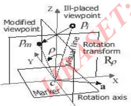
III. Orientation modification by error model
We define a “visual-line angle” as a zenith-angle of visual line to the marker. It can be divided into θvxc (around x-axis) and
Reference points Black peak
1
2 3
Vertical stick
θvyc (around y-axis) (Fig. 4(a)). We confirmed that the invalid orientation estimation is a phenomenon in which the signs of the visual-line angles are inverted. We call this geometrical model an “error model” of the invalid estimations caused by the pose ambiguity. When we detect an invalid estimation, we modify theorien- tation by rotation transform, based on the error model (Fig. 4( b)). This modification is done in the same way described in [8].
Figure 4(a): virtual line angle (θvxc)
Figure 4(b): Orientation modification by inverting visual line angles.
IV. DISCUSSION AND FEATURE APPROACHES
However, the VMP method is not applicable in larger angle area,hence the invalid estimations still remain unresolved when the absolute value of either visual-line angle is more than about 10[deg]. We can eliminate these residues by the ARP added in this study. In this way, we realized stable orientation estimation in wide angle range, and solved the big two problems of the conventional fiducial markers.
For reference, we also show the result of “Ref. Using ARP only”. Compared with the results by the VMP, the estimation of the circledparts is not so stable. It is because the error model in frontal direction is different from that of the pose ambiguity. Therefore, we need the VMP to modify the orientation errors in frontal direction.
We proposed a practical solution which works well on small markersand cheap cameras. Though we introduced a three-dimensional structure, the ratio of the height to the long side of the marker is only
about 0.1. This is a benefit brought by our strategy, in which we use the ARP not for pose estimation but for error detection. The error(invalid estimation) is easily detected even by using a noisy cheapcamera and a not-so-accurate geometrical model of the ARP. If we use the ARP for pose estimation by using PnP techniques like [9], we need at least two ARPs placed on higher position. They will make shadows, hide other feature points, and need very accurate geometrical models. It is not practical. Bokode [10] is another high accuracy small marker having three-dimensional structure. Unlike the ArrayMark, it needs internal lighting, and cannot be recognized by a usual camera. Thus it is not suitable for practical use in AR. In the category of the planar marker, random dot markers [11] and Uniform Marker Fields [12] might contribute to stabilize the orientation estimation. However, they are designed to cover large areas in images, thus their methods are not applicable to smaller markers like the ArrayMark.
V CONCLUSION
[image:5.612.34.257.206.622.2] [image:5.612.33.255.439.619.2]human-living environment. The ArrayMark solved the big two unresolved problems of the conventional markers. It brings great benefits to many applications, e.g. augmented reality, robotics, and measurement. We will continue further development for more robust and accurate ArrayMark in real environments, working towards realization useful in practice.
VI. REFERENCES
[1]Hideyuki Tanaka,Yasushi Sumi,Yoshio Matsumoto:” Farther stabilization of a microlens-array-based Fiducialmark- er”1 - 4 October2013, Adelaide, SA, Australia 978-1-4799-2869-9/13/$31.00©2013 IEEE
[2]Sandy Martedi, Maki Sugimoto, Hideo SaitoMai Otsuki, Asako Kimura, Fum-ihisa Shibata:”A Tracking Method for 2D canvas in MR-based interactive painting system” 2013 International Conference on Signal-Image Techno- logy & Internet-Based Systems ,978-1-4799-3211-5/13 $31.00 © 2013 IEEEDOI 10.1109/SITIS.2013.128
[3]Li Yi-bo, Kang Shao-peng, Qiao Zhi-hua, Zhu Qiong “Development Actu-ality and Application of Registration technology in Augmented Reality”978-0-7695-3311-7/08 $25.00©2008 IEEE DOI 10.1109/ISCID.2008.120.
[4]R. Hartley and A. Zisserman. Multiple View Geometry in computer-vision.Cambridge University Press, 2004.
[5]G. Schweighofer and A. Pinz. Robust pose estimation from a planar target. In IEEE Transactions on Pattern Analysis and Machine Intelligence, Vol. 28(12), pp. 2024–2030, 2006.
[6] Lourakis, M. “levmar: Levenberg-marquardt nonlinear leastsquares algorithms in C/C++.” [web page]http://www.ics.forth.gr/~lourakis/levmar/, Jul. 2004. [Accessed on 23 Aug. 2013.].
[7]C. Lu, G. Hager, and E. Mjolsness, Fast and globally convergent pose estimation from video images,. IEEE Transactions on PatternAnalysis and Machine Intelligence, vol. 22, no. 6, pp. 610.622, June 2000.
[8]H. Tanaka, Y. Sumi, and Y. Matsu- moto. A high-accuracy visualmarker based on a microlens array. In Proc-eedings of 2012 IEEE/RSJIntl. Conf. on Intelligent Robots and Systems, pp. 4192–4197, 2012.
[9] V. Lepetit, F. Moreno-Noguer, and P. Fua. EPnP: An accurate O(n)solution to the PnP problem. In International Journal of ComputerVision, Vol. 81(2), pp. 155–166, 2009.
[10] A. Mohan, G. Woo, S. Hiura, Q. Smit-hwick, and R.Raskar. Bokode: imper- ceptible visual tags for camera based interaction from a distance.InACM Transactions on Graphics, Vol. 28(3), No. 98, 2009.
[11]H. Uchiyama and H. Saito. Random Dot markers. In Proceedings of IEEE Virtual Reality, pp. 35–38, 2011.
[12] I. Szentandrasi, M. Zacharias, J. Havel, A. Herout, M. Dubska, and R. Kajan. Uniform Marker Fields: Camera localization by orientable De BruijnTori. Proceedings of 2012 IEEE International Symposium onMixed and