Technology (IJRASET)
Design and Implementation of Inverter for
driving Induction Motor using DSPACE
L. Vinod Kumar1, Syed Sarfaraz Nawaz2
1
MTech Student Department of Electrical Engineering, GRIET, Hyderabad-500072
2
Assoc Professor in the Department of Electrical Engineering, GRIET, Hyderabad-500072
Abstract— This paper presents the design and implementation of inverter system for driving both single phase , three phase Induction motor using DSPACE with the controlling objectives PWM and SVPWM . AC motor drives are widely used to control the speed of pumps, blowers, machine tool speeds, conveyor systems etc that require variable speed with variable torque. The project will be commenced by a basic understanding of the PWM, SVPWM Inverters, the components used in its design. After this it will be attempted to simulate using MATLAB and further enhanced through hardware circuit by interfacing through DSPACE and analyse the output waveforms for various values of the elements used in the circuit and hence study the system response and instabilities. Here the hardware unit of Single phase Inverter driving Induction Motor is implemented using DSPACE.
Keywords— Pulse width modulation (PWM), Space Vector Pulse Width Modulation (SVPWM), Digital Signal Processor for
Applied and control Engineering (DSPACE).
I. INTRODUCTION
An inverter is basically a power electronic device that converts electrical energy of DC form into that of AC. These DC-AC inverters have been widely used for industrial applications such as uninterruptible power supply (UPS), AC motor drives. Recently, the inverters are also playing an important role in various renewable energy applications as these are used for grid connection of Wind Energy System or Photovoltaic System. In addition to this, the control strategies used in the inverters are also similar to those in DC-DC converters. Both current-mode control and voltage-mode control are employed in practical applications. The DC-AC inverters usually operate on Pulse Width Modulation (PWM), Space vector Pulse Width Modulation (SVPWM) techniques. The PWM is a very advance and useful technique in which width of the Gate pulses are controlled by various mechanisms. PWM inverter is used to keep the output voltage of the inverter at the rated voltage (depending on the user’s choice) irrespective of the output load .many industrial processes. Industrial applications of inverters are for adjustable-speed AC drives, UPS (uninterruptible power supply), HVDC transmission lines and etc. The DC power input to the inverter maybe battery, fuel cell, solar cell or other DC source. But in most industrial applications, it is fed by a rectifier.
There are commonly two types of inverters, voltage source inverters (VSI) and current source inverters (CSI). When an inverter has a DC source with small or negligible impedance, which means the inverter has a stiff DC voltage source at its input terminal, it is called a VSI or voltage fed inverter (VFI). When the input DC source has high impedance, which means the DC source has a stiff DC current source, the inverter is called a CSI or current fed inverter (CFI). In this the hard ware implementation of single phase and three phase voltage source inverters will be discussed.
Technology (IJRASET)
A. Applications of Inverter:
1) Electric Motor Speed Control.
2) Induction Heating.
a) Phase Opposition Disposition (POD)
b) Alternative Phase Opposition Disposition (APOD)
c) Phase Disposition (PD)
3) HVDC Power Transmission.
4) Portable consumer devices that allow the user to connect a battery, or set of batteries, to the device to produce AC power to run various electrical items such as lights, televisions, kitchen appliances, and power tools.
5) Use in power generation systems such as electric utility companies or solar generating systems to convert DC power to AC power.
6) Use within any larger electronic system where as engineering need exists for deriving an AC source from a Dc source. II. INDUCTIONMOTOR
An Induction or asynchronous motor is an AC electric motor in which the electric current in the rotor needed to produce torque and this torque is obtained by electromagnetic induction from the magnetic field of the stator winding. An induction motor therefore does not require mechanical commutation, separate excitation or self excited for all or part of the energy transferred from stator to rotor, as in universal, DC and large synchronous motors. An induction motors rotor can be either wound type or squirrel cage type. Three-phase squirrel-cage induction motors are widely used in industrial drives because they are rugged, reliable and economical. Single-phase induction motors are used extensively for smaller loads, such as household appliances like fans. Although traditionally used in fixed-speed service, induction motors are increasingly being used with variable-frequency drives (VFDs) in variable-speed service. VFDs offer especially important energy savings opportunities for existing and prospective induction motors in variable-torque centrifugal fan, pump and compressor load applications. Squirrel cage induction motors are very widely used in both fixed-speed and VFD applications.
A. Construction
The stator of an induction motor consists of poles carrying supply current to induce a magnetic field that penetrates the rotor. To optimize the distribution of the magnetic field, the windings are distributed in slots around the stator, with the magnetic field having the same number of north and south poles. Induction motors are most commonly run on single-phase or three-phase power, but two-phase motors exist; in theory, induction motors can have any number of two-phases. Many single-two-phase motors having two windings can be viewed as two-phase motors, since a capacitor is used to generate a second power phase 90° from the single-phase supply and feeds it to the second motor winding. Single-phase motors require some mechanism to produce a rotating field on start-up. Cage induction motor rotor's conductor bars are typically skewed to reduce noise.
B. Rotation Reversal
The method of changing the direction of rotation of an induction motor depends on whether it is a three-phase or single-phase machine. In the case of three phase, reversal is carried out by swapping connection of any two phase conductors. In the case of a single-phase motor it is usually achieved by changing the connection of a starting capacitor from one section of a motor winding to the other.
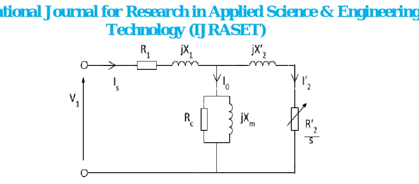
C. Equivalent Circuit
Technology (IJRASET)
Figure 3. Equivalent Circuit of an Induction Motor
D. Principle of Operation
In both induction and synchronous motors, the AC power supplied to the motor's stator creates a magnetic field that rotates in time with the AC oscillations. Whereas a synchronous motor's rotor turns at the same rate as the stator field, an induction motor's rotor rotates at a slower speed than the stator field. The induction motor stator's magnetic field is therefore changing or rotating relative to the rotor. This induces an opposing current in the induction motor's rotor, in effect the motor's secondary winding, when the latter is short-circuited or closed through external impedance. The rotating magnetic flux induces currents in the windings of the rotor, in a manner similar to currents induced in a transformer's secondary winding(s). The currents in the rotor windings in turn create magnetic fields in the rotor that react against the stator field. Due to Lenz's Law, the direction of the magnetic field created will be such as to oppose the change in current through the rotor windings. The cause of induced current in the rotor windings is the rotating stator magnetic field, so to oppose the change in rotor-winding currents the rotor will start to rotate in the direction of the rotating stator magnetic field. The rotor accelerates until the magnitude of induced rotor current and torque balances the applied load. Since rotation at synchronous speed would result in no induced rotor current, an induction motor always operates slower than synchronous speed. The difference, or "slip," between actual and synchronous speed varies from about 0.5 to 5.0% for standard Design B torque curve induction motors.
[image:4.612.198.450.567.709.2]The induction machine's essential characters that it is created solely by induction instead of being separately excited as in synchronous or DC machines or being self-magnetized as in permanent magnet motors. For rotor currents to be induced, the speed of the physical rotor must be lower than that of the stator's rotating magnetic field ( ); otherwise the magnetic field would not be moving relative to the rotor conductors and no currents would be induced. As the speed of the rotor drops below synchronous speed, the rotation rate of the magnetic field in the rotor increases, inducing more current in the windings and creating more torque. The ratio between the rotation rate of the magnetic field induced in the rotor and the rotation rate of the stator's rotating field is called slip. Under load, the speed drops and the slip increases enough to create sufficient torque to turn the load. For this reason, induction motors are sometimes referred to as asynchronous motors. An induction motor can be used as an induction generator, or it can be unrolled to form a linear induction motor which can directly generate linear motion.
Technology (IJRASET)
The typical speed-torque relationship of a standard NEMA Design B poly phase induction motor is as shown in the curve. Suitable for most low performance loads such as centrifugal pumps and fans, Design B motors are constrained by the following typical torque ranges.
1) Breakdown torque, 175-300 percent of rated torque
2) Locked-rotor torque, 75-275 percent of rated torque
3) Pull-up torque, 65-190 percent of rated torque.
E. Dynamic Modelling of Induction Motor
A dynamic model of the machine subjected to a control must be known in order to understand and design the vector controlled drives. Such a model can be obtained by means of either the two-axis theory or spiral vector theory of electrical machines. Following are the assumptions made for the model.
1) Each stator winding is distributed so as to produce a sinusoidal mmf along air gap, i.e. space harmonics are negligible.(Sinusoidal induction repartition)
2) The slotting in stator and rotor produces negligible variation in respective inductances.
3) Mutual inductances are equal
4) The harmonics in voltages and currents are neglected. Saturation, hysteresis and eddy effects negligible.
Figure 5. Two Axis representation of IM
Equations corresponding to the two axis representation of Induction Machine are reduced through KVL as follows
Vqs = Rq iqs + P(Lqq iqs ) + P( Lqd ids) + P( Lqα id) + P( Lqβ iβ)---1
Vds = P (L dq iqs) + Rd ids + P (Ldd ids) + P (Ldd id) + P (Ldβ iβ)----2
Vα = P (Lαq iqs) + P (Lαd ids) + Rα iα + P (Lαα iα) + P (Lαβ iβ) ----3
Vβ = P (L pq iqs) + P (Lpq ids) + P (Lβα iα) + R β iβ + P (Lββ iβ)---.4
Lαα =Lββ = Lrr Lαβ = Lβα = o Ldd = Lqq = Lss Ldq = Lqd = o
Lαd = Ldα = Lsr cos θr
Lβd = Ldβ = Lsr sin θr
Lαq = Lqα = Lsr sin θr
Lpq = Lqβ = -Lsr cos θr
With respect to the fictitious rotor
iα = idrr cos θr + iqrr sinθr
iβ = idrr sin θr + iqrr cosθr
with respect to the arbitrary reference frame
ids = ic ds cosθc -icqs sinθc
ids = ic ds cosθc +icqs sinθc
Technology (IJRASET)
Vcqs Rs+Ls p -wc Ls Lm.P -wc Ls Vcqs
Vcds -wc Ls Rs+Ls p -wc Ls Lm.P Vc ds
Vcqr Lm.P - (Wc-Wr)Lm Rs+Ls p - (Wc-Wr)Lm Vcqr
Vcqr - (Wc-Wr)Lm Lm.P - (Wc-Wr)Lm Rs+Lsp Vcdr
Torque: V=[R] i + [L] Pi +[G]wr i + [F] Wc i
It.V = it[R] + it[L]P i + it[G] wr i + it[F] wci
it[L]P i Rate of change of stored magnet energy it[G] .wr I Air gap power = Mech Rot speed x Air gap
WnTe = Pa = it[G] I x Wr
Te = P/2 it[G] i
[G] i = it 0 0 0 0 icqs
0 0 0 0 icds
0 -lm 0 -lr icqr lm 0 lr 0 icdr
It[G] i= Lm [icqs icdr – icdsicqr]
Te = 3/2 .P/2 Lm (icqs icdr – icds icqr)
Te = 3/2. P/2 . 1/wb [ ψcds .icqs- ψcqs .icds]
Through the above analysis speed, torque of an Induction Motor can be controlled by voltage current parameters.
III. INVERTER
There are many types of inverters available and each of them is designed to suit a particular application or to meet designed performance requirements. Generally inverters are categorized into two main types:
A. Single phase Inverter:
[image:6.612.185.425.484.585.2]The power circuit diagram of a single phase full bridge inverter is shown below. It consists of two arms with a two semiconductor switches on both arms with anti-parallel freewheeling diodes for discharging the reverse current. In case of resistive-inductive load, the reverse load current flow through these diodes. These diodes provide an alternate path to inductive current which continue so flow during the Turn OFF condition.
Fig 6. Single Phase Inverter
The switches are T1, T2, T3 and T4. The switches in each branch is operated alternatively so that they are not in same mode (ON /OFF) simultaneously .In practice they are both OFF for short period of time called blanking time, to avoid short circuiting. The switches T1 and T2 or T3 and T4 should operate in a pair to get the output. These bridges legs are switched such that the output voltage is shifted from one to another and hence the change in polarity occurs in voltage waveform. If the shift angle is zero, the
output voltage is also zero and maximal when shift angle is π.
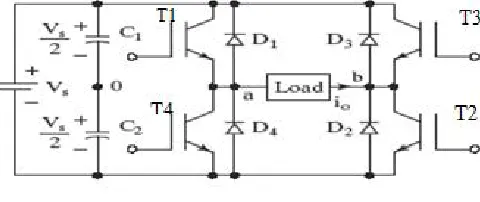
Three phase Inverter:
Technology (IJRASET)
connected at the input terminal to make the DC input constant and also suppress the harmonics fed back to the source.
[image:7.612.175.453.132.523.2]There are two patterns of gating transistors. In one pattern, each thyristor conducts for 180o and in the other, each transistor conducts 120o. But both patterns’ gating signals are applied and removed at 60ointervals of the output voltage waveform. Both modes require a six step bridge inverter.
Figure 7. Three phase Inverter
Figure 8 output line voltage and phase voltage of three phase Inverter
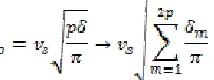
B. Pulse Width Modulation
1) Sinusoidal pulse width modulation: In this modulation technique multiple numbers of output pulse per half cycle and pulses are of different width. The width of each pulse is varying in proportion to the amplitude of a sine wave evaluated at the Centre of the same pulse. PWM control requires the generation of both reference and carrier signals that are feed into the comparator. The rms ac output voltage
Where p=number of pulses and δ= pulse width
[image:7.612.257.364.618.658.2]Technology (IJRASET)
Figure 9 sinusoidal pulse width modulation
2) Space Vector Pulse Width Modulation: SVM is an advanced computation-intensive PWM method and possibly the best PWM techniques for three phase inverters. SVPWM refers to special switching sequence of the upper three power transistors of a three-phase power inverter. It has been shown to generate less harmonic distortion in output voltages and current applied to the phases of an AC motor and to provide more efficient use of supply voltage compared with sinusoidal modulation technique. Here the symmetrical conduction mode of operation of SVM is used to ensure the reduction of harmonics at the inverter output. In the Symmetrical conduction mode, to overcome commutation problem dead time has to be introduced by allowing zero voltage vector before and after of each conduction cycle.The circuit of a typical three-phase voltage source PWM inverter is shown above in figure 4, s1 to s6 are the six power switches that shape the output, which are controlled by the switching variable a, a’, b, b’, c and c’. When an upper transistor is switched on i.e. when a, b or c is 1, the corresponding lower transistor is switched off, i.e., the corresponding a’, b’ or c’ is 0. Therefore, the on and off states of the upper transistors s1, s3 and s5 can be used to determine the output voltage.
The relationship between the switching Va vector [a, b, c]t and the line-to-line voltage vector [Vab, Vbc, Vca ]t is given by
= Vdc
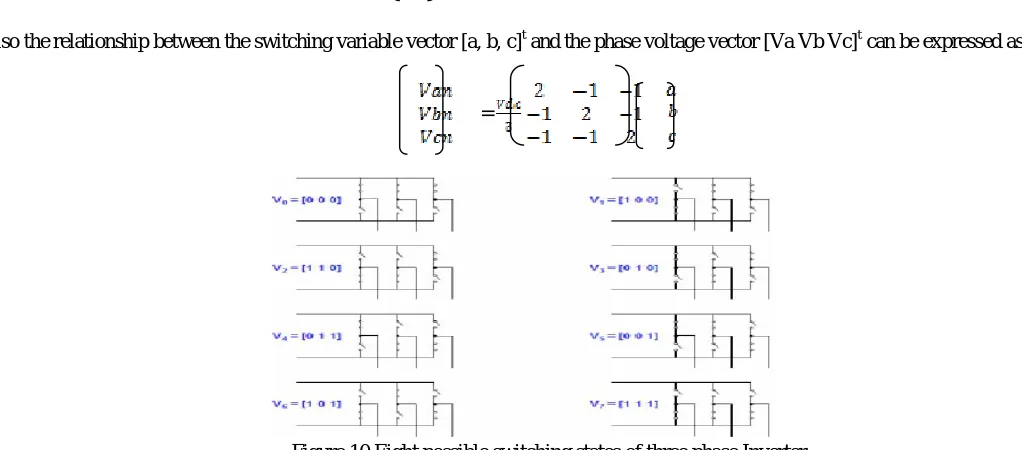
Also the relationship between the switching variable vector [a, b, c]t and the phase voltage vector [Va Vb Vc]t can be expressed as
=
Figure 10 Eight possible switching states of three phase Inverter
As illustrated in above figure, there are eight possible combinations of on and off patterns for the three upper power switches. The on and off states of the lower power devices are opposite to the upper one and so are easily determined once the state of the upper power transistors are determined.
Technology (IJRASET)
TABLEI
SWITCHINGVECTORSANDOUTPUTVOLTAGES
voltage Switching Vectors
Line to Neutral Voltage
Line to Line Voltage
A B C
0 0 0 0 0 0 0 0 0
1 0 0 2/3 -1/3 -1/3 1 0 -1
1 1 0 1/3 1/3 -2/3 0 1 -1
0 1 0 -1/3 2/3 -1/3 -1
0 1
0 1 1 -2/3 1/3 1/3 -1
0 1
0 0 1 -1/3 -1/3 2/3 0 -1 1
1 0 1 1/3 -2/3 1/3 1 -1 0
1 1 1 0 0 0 0 0 0
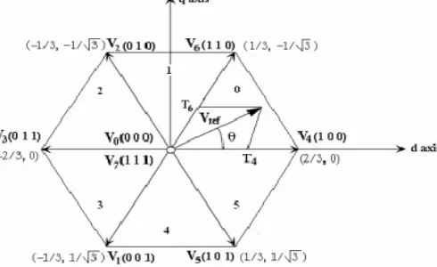
In order to implement the SVPWM, voltage equations in the abc reference frame should be transformed into the stationary d-q reference frame. This transformation is equivalent to an orthogonal projection of [a, b, c]t on to the two dimensional perpendicular to the vector [1, 1,1]t in a three-dimensional coordinate system. As a result, six non zero vectors (V1-V6) shape the axes of a hexagonal and feed electric power to the load.
[image:9.612.201.446.426.576.2]The angle between any adjacent two non-zero vectors is 60 degrees. Meanwhile, two non zero vectors (V0 and V7) are at the origin and apply zero voltage to the load. The eight vectors are called the basic space vectors and are denoted by V0, V1, V2, V3……V7. The same transformation can be applied to the desired output voltage to get the desired reference voltage vector Vref using the eight switching patterns.
Figure 11. Basic Switching vectors and Sectors
IV. SIMULINKANDHARDWARE
Matlab is an interactive software system for numerical computations and graphics. Modelling, Simulink provides a graphical user interface. Simulink includes comprehensive blocks libraries of sinks, linear, nonlinear components and connectors. We can create our own blocks. Models are hierarchical with increasing levels of model details. This approach provides insight into how a model is organized and how its parts interact.
Technology (IJRASET)
Technology (IJRASET)
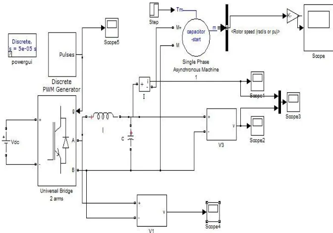
[image:11.612.161.466.250.464.2]Fig 13. PWM Pulses, Output voltage, current and Speed of the single phase Induction Motor.
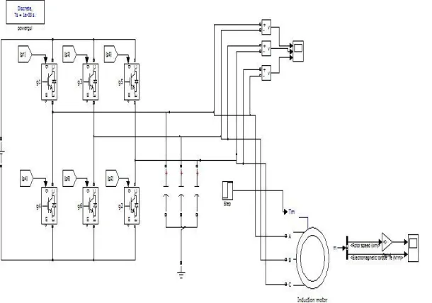
Fig 14. Simulink of the three phase Inverter.
[image:11.612.153.455.478.699.2]Technology (IJRASET)
Fig.16. Gate pulses generate by SVPWM for driving three phase inverter.
Figure.17 Output line voltages, speed and Torque of a three phase IM.
V. DSPACE CONTROLLER
Technology (IJRASET)
[image:13.612.45.551.60.376.2]
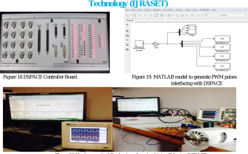
Figure 18 DSPACE Controller Board Figure 19. MATLAB model to generate PWM pulses interfacing with DSPACE
Figure 20 Hardware unit of Single phase Inverter driving IM using DSPACE
The hardware unit comprises of the DSPACE unit installed to a desktop wherein the MATLAB files can be interfaced through the DSPACE package software. Single phase Inverter is been designed with an isolation circuit to protect the controller board from the sudden voltage fluctuations feeding back to the controller board. Pulses from the controller board reaches the switches through the isolation circuit through opto-couplers EL817, pulses passes through the EL817 by light manner.
Inverter feeds the Induction Motor, speed of the Induction Motor can be controlled by varying the pulse width as shown in CRO. DSPACE unit operates for 250MHz and the pulse width generated is of 2k frequency. DSPACE unit comprises of 8 analog and 8 digital pins. 20 input and output signals can be interchanged randomly. Input to the Inverter unit is 230volts where the output of the Inverter received is 227 Volts 1 A.
VI. CONCLUSIONS
This paper work provides the successful attempt to analyse the PWM and SVPWM for the Inverter systems. Matlab/simulink software results are provided and DSPACE interfacing has been done successfully. PWM, SVPWM pulses generated by the controller board have been shown clearly. Sinusoidal PWM inverter output voltage maintains good performance of the drive in the entire speed range operation with less control on each switching instant. SVPWM inverter technique utilizes dc bus voltage more efficiently and the maximum output voltage based on the space vector technique is 1.155 times as large as the conventional sinusoidal modulation. It generates less harmonic distortion in a three phase voltage source inverter. Hardware unit of Single phase Inverter driving IM in open and closed loop have been done successfully and further it can be extended to implement hardware unit of three phase IM in both open and closed loop.
REFERENCES
[1] Advanced Micro processors and Peripherals by A K Ray and K M Bhurchandi, Tata McGraw Hill Private Limited.
[2] “DSPACE direct torque control Implementation for induction motor” by A.Abbou , Y Sayouti, H Mahmoudi M. Akherraz in 18th Mediterranean Conference on Control &Automation.
[3] M. Chomat, T.A. lipo, Adjustable Speed single phase IM drive with reduced number of switches, IEEE Trans. Ind. Appl.39 (3) (2003).
[image:13.612.52.525.241.370.2]Technology (IJRASET)
Power Electronics and Applications, 1989, pp. 1197-1202.
[6] Modern Power Electronics and AC Drives, by Bimal K. Bose. Prentice Hall Publishers. [7] Power Electronics by Dr. P.S. Bimbhra. Khanna Publishers, New Delhi.