3D Simulation of Real-Time Tracking of Flights
in ATC
Arif abdul rahman A,1, P.S.B Kirubakaran. M.S 2
Avionics Engineering, School of Aeronautical Sciences, Hindustan University, Chennai, India
Abstract— Using 3D simulation technique real-time flight tracking and guiding for the pilot is done for the convenience
of the Air Traffic Controller. The job of the air traffic controller is very technical and very stressful. The air traffic controller monitors the weather, flight handling of all aircrafts in the coverage area and guides the pilot accordingly for take-off, landing, en route and order the pilot during critical situations and avoiding collisions. At present the air traffic controller guides the pilot in landing and take-off by visually monitoring around the airport using radar systems and in the runway using binoculars. The flights in the coverage area of particular airport control tower are monitored using radar systems. The radar system gives time to time update air data information about flights. With this 2D visual information the air traffic controller guides the pilot. By constructing 3D scene model library and aircraft model, the rendering and integration of visual scene with the real-time flight data are implemented. The flight models get positioned according to the air data that we get from the ADS-B network. Integrating these data with the flight models is done as simulation with the matlab simulink. The 3D visual flight monitoring system in the ATC enables the Air Traffic Controller to control the aircraft easily with their 3Dimentional view of position of the aircraft relative to ground and terrain. And also shows the maneuvers of all aircraft with their air data information tagged to them. The altitude, distance, heading of all flights is visually seen 3Dimensionally, which will make Air Traffic Controller clearly track, see the altitude clearance between the flights and avoids collisions.
Keywords— 3D simulation; real-time tracking; air traffic control I. INTRODUCTION
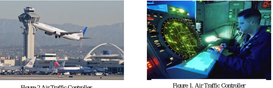
The Air Traffic Control (ATC) is the control tower with two divisions which monitors and controls the flight in that tower control. The Air Traffic Control normally has two control rooms one operates in the dark room and other operates in the visual landing and takeoff of flights. The dark room environment is to provide clear and focused visuals of the flight around the Air Traffic Control tower. The people here will monitor, en route and guide the pilot to avoid collisions. The total flight monitoring and en routing the pilot around the control of the airport tower range is done by the dark room operators. In the other section the Air Traffic Controller visually monitor the runway and sets the Aircraft for takeoff and landings. The work of the ATC controller is a very risky job. The pilot just hears the words of ATC controller and follows their commands.
Figure 2.Air Traffic Controller
[image:2.612.64.510.481.625.2]The display in the ATC is 2D display. The output i.e. the representation of the runway and pattern of all the aircraft seen are only the 2D representation in the radar screen. The air traffic controller by seeing the aircraft tag, flight number altitude heading speed and position are known from the radar. By real time tracking of the flight data with the help of AirNav software, aircraft position information and other data’s are known without the help of the radar. The purpose of 3d simulation is to achieve real time tracking of flight in the able environment without the help of the radar. By Achieving 3D visualization in the 2D displays, it will make the air traffic controller easier to visualize the flights in 3D form and also enable him to monitor and control the aircraft easily. This reduces the risk of air traffic controller and helps him in seeing the clearance between the flights and also avoids the
Technology (IJRASET)
collisions very easily.
II. DESIGNANDDEVELOPMENTPROCESSOFFVSS
The Flight visual simulation system is created with two modules, one is the flight simulation and the other is the visual simulation. The flight simulation required the 3D modeling of the aircraft, the aerodynamic equations and these equations generates the aerodynamic moments for the 3D models. For the visual simulation we need to construct flight scenes. The flight scenes are generated in the open flight format. The scenes contain the motion of the aircraft, terrain, scene scenario, climatic conditions such as fog, mist, clouds, rainfall, etc.
For the creation of 3D models and rendering this model and driving in accordance with real-time data the software tool called Creator and Vega prime was used. These tools help in creation, rendering and scene driving of the models. The real time data is integrated with the system as the xml files. The matlab simulink tool helps in integration of the data with the visual scene models.
III.REAL-TIMETRACKING
Real time data is the source for my project work. Since the radar hardware is required to get real-time fight data it is difficult, to get the radar for this purpose. So choosing the ADS-B network data the real time data is taken. The real –time data, which is at present information such as altitudes heading, position, etc are obtained from AirNav radarbox as xml data.
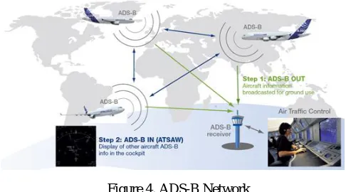
A. ADS-B Network
The information provided by ADS-B enhances the pilots' traffic awareness, allowing more optimal flight levels leading to fuel savings.
ADS-B is considered in two parts as described:
ADS-B OUT provides a means of automated aircraft parameter transmission between the aircraft and the ATC.
ADS-B IN provides automated aircraft parameter transmission between aircraft themselves [7].
IV.3DMODELING
[image:3.612.184.427.463.598.2]The 3D modeling and crating the flight models with less loader files the Creator tool is used. The 3D models are created with the help of this tool. Creator supports in removing of excess polygons, since the time taken to render and drive the models with more number of polygons will take more time. The terra page includes the terrain database and attaches the flight models with respect to the geometry and location as we feed in the options. The terrain files are shown only up to the level where we want. These factors are considered in order to decrease the loading time. The advanced real-time functions of this software, such as LOD, polygon screening, logic screening, drawing priority and separation surface, make the Open Flight (.flt) file the most popular image format in real-time 3D field[6].
Figure 3. Actual development process of the FVSS
V. MODELGENERATION
In visual simulation systems, loading capacity and rendering efficiency are directly affected by model size, model quantity and range of region terrain. Model optimization is an important step during the design and implementation process because optimized model can provide better authenticity and real-time display. Following optimization techniques are applied for 3D
modeling in this paper.
At the first the excess polygons and triangles were removed. The open flight file is got from the internet and this file is edited in creator to remove the excess polygons. The modification is done because the loading takes place for a very longer time. The triangles were removed in all the faces, such that the appearance of the flight model does not change.
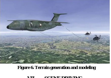
VI.TERRAINMODELING
Terrain modeling is the creating of the aerodrome, ATC tower, radar and other essential things with fixed 3D models. The terrain also includes details other than airports such as buildings, mountains, trees, sea, etc. while driving the scene with the terrain placed in the globe all the details could not be loaded at the same time, only the required details that are visually seen during the position of the camera is only loaded. This type of loading data is called LoD (Level of Detail). By loading only the required data the time for visualizing the details is saved. For getting loaded the terrain files some data formats have to be changed. The initial step is to get the SRTM data files. These are the satellite images which can be downloaded from the Consortium for Spatial Information.
These data files are converted to .DED files by suitable tools. This file then loaded in the creator and integrated for the location were need to be visually imparted.
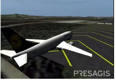
VII. SCENEDRIVING
[image:4.612.193.419.138.224.2]The version of this template is V2. Most of the formatting instructions in this document have been compiled by Causal Productions from the IEEE LaTeX style files. Causal Productions offers both A4 templates and US Letter templates for LaTeX and Microsoft Word. The LaTeX templates depend on the official IEEEtran.cls and IEEEtran.bst files, whereas the Microsoft Word templates are self-contained. Causal Productions has used its best efforts to ensure that the templates have the same appearance.This is the important part in visualizing the scene with the real time data. The vega prime tool supports us in creating the scenario and delivering the data. The vega prime call function which enables to load the real-time scenario, with this scenario and terrain model the 3D model flight is generated with actual present live flight data. The real happening in the outer space is visually driven in the ATC tower. After integrating the models with the real-time ADS-B network data the 3D model libraries are called according to the aircraft take-off and landings. The exact flight models can be integrated with the data, after further programming and creating the whole world flight data. The 3D models will be called by a simple program. All the scene models are driven after calling upon the scene libraries. This function is enabled by the preprogrammed vpapp. The
Figure 5. Creator Profile editor
[image:4.612.197.417.420.575.2]Technology (IJRASET)
sample vega prime application is given below and used throughout this runtime [7].
#include <vpApp.h>
int main(int argc, char *argv[])
{
// initialize vega prime
vp::initialize(argc, argv);
// create a vpApp instance
vpApp *app = new vpApp;
// load acf file
if (argc <= 1)
app->define("kitty hawk500.acf");
else
app->define(argv[1]);
// conFig. my app
app->conFig.();
// frame loop
app->run();
// unref my app instance
app->unref();
// shutdown vega prime
vp::shutdown();
return 0;
}
VIII. CONCLUSIONS
[image:5.612.349.553.83.251.2]The real-time tracking of flights is approached by getting real-time flight data from ADS-B network via AirNav radarbox tool. This .dat files are added in vega prime. The scene is rendered accordingly with real-time flight motion as exactly as the outer
[image:5.612.63.301.86.250.2]world. Thus for the Air traffic controller it will be easy to navigate and have better visualization in take-off and landing of aircraft.Causal Productions permits the distribution and revision of these templates on the condition that Causal Productions is credited in the revised template as follows: “original version of this template was provided by courtesy of Causal Productions (www.causalproductions.com)”.
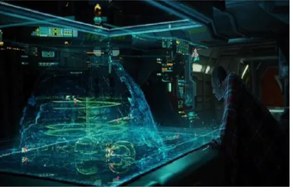
IX.FUTUREENHANCEMENT
My actual dream is to guide the pilot from the ATC tower with the help of 3D holographic projection technology. The outer terrain and aircraft models are visually seen as it appears in real world. Using the 3D holographic projection in table the real happening in the aerodrome will be seen inside the ATC tower as 3D virtuals. It will be more helpful for the air traffic controller to navigate and en route the pilot.
X. ACKNOWLEDGMENT
We deeply indebted to my parents, friends and well-wishers who have been the greatest support while we worked day and night for the project to make it a success.
REFERENCES
[1] Ahmed Elmorshidy, Ph.D “Holographic Projection Technology: The World is Changing.” JOURNAL OF TELECOMMUNICATIONS, VOLUME 2, ISSUE 2, MAY 2010
[2] Eric F. Sorton, Sonny Hammaker, “Simulated Flight Testing of an Autonomous Unmanned Aerial Vehicle Using FlightGear”, In Proceedings of AIAA Guidance, Navigation, and Control Conference and Exhibit, pp.1~13, 2005
[3] Feng Tian, “Design and Implementation of Flight Visual Simulation System”, Shenyang Aerospace University, 110136 Shenyang, China [4] http://vterrain.org/Packages/Com/
[5] http://www.airnavsystems.com/radarbox/ [6] Multigen Paradigm Inc. Vegaprime Options Guide. [7] Multigen Paradigm Inc. Vegaprime Programmer’s Guide.
[8] Automatic Dependent Surveillance Broadcast (ADS-B) Surveillance development for Air Traffic Management (Airbus)
[9] International Civil Aviation Organization (ICAO), “Advanced Surface Movement Guidance and Control Systems (A-SMGCS) Manual”, Doc. 9830, First Edition, Montreal, Canada, 2004
[10] L. Mazzuchelli, "The 4D Virtual Airspace Management System," European Commission 6th Framework Project, DG-RTD 2005. [11] Lu ming. Design of Primary Training Aircraft Flight simulator. Liaoning Technical Universtiy. (2009)
[12] Lu ping. Research on Visual Simulation System of Flight Simulator. Jilin Universtiy. (2008) [13] M. Pauly and G. Greiner, “Time-of-Flight Sensors in Computer Graphics”, EUROGRAPHICS 2009
[14] M. St. John, S. Smallman, T., and M. Cowen, B., "The Use of 2D and 3D Displays for Shape-Understanding versus Relative-Position Tasks," 2001 [15] TANG Yong, HU Minghua, WU Honggang, “3D Simulation of A-SMGCS Surface Movement based on FlightGear”, National Science and Technology
Pillar Program of China (Grant No.2011BAH24B05, 2011BAH24B06
[image:6.612.211.425.198.339.2]This is Arif Abdul Rahman A, I’m pursuing M.Tech -Avionics Engineering in Hindustan University. I know that in future 3D simulation for real time imaging is one who will rule the world. So, I decided to work in to this with some innovation for this.