Basic Programming Concepts
and
The IBM 1620 Computer
Basic Programming Concepts
and
Date: Sat, 4 Apr 2009 09:22:13 -0700 From: "Dan Leeson"
You are welcome to scan the copy you have of my book, and submit the scan to the IBM 1 620 section of the bitsaver.org archives. Be my guest.
Every now and then, I bump into people whose first introduction to computing was through the IBM 1 620 and who did so using my book. Frankly, I am flattered to have played a small role in the history of the computer business. I live near the computer history museum in Mountain View, California, and every now and then I find something in my attic to donate to them. What I will not donate is a special, leather-bound copy of the book, given to me by the publishers after it had sold a great many copies. Don Dimitry and I wrote the book without any expectations that it would become a best seller for its day. But it did.
Thanks for making my day and finding some use to what is now an obsolete book, though it was a killer in its brief time ..
Basic Programming Concepts
and
•
IB~ 1620 Symbolic Programming System
•
Coding Sheet
•
PrQlilrQm PageNo·Wof _ _
Progn;lInmed by Oate _ _ _
BASIC
PROGRAMMING CONCEPTS
AND
THE IBM 1620 COMPUTER
Daniel N. Leeson
Donald
L.
Dimitry
Copyright © 1962 by Holt, Rinehart and Winston, Inc. All rights reserved
Library of Congress Catalog Card Number: 62-19796
25194·0112 75194·0212
For
Preface
Construction of a text on computers usually takes one of two directions: (1) general computer philosophy stressing engineering design, scientific-commercial applications, and a variety of related subjects such as Boolean algebra, switching circuit theory, and so forth, or (2) the total organization of a single computer (possibly an imaginary one) with the tacit assumption that one learns an entire range of computers by studying a particular one.
There is a variety of excellent books on general computer philosophy (see "Reading Reference"). However, we have decided to take the latter tack and generate a book on one specific computer whose popularity makes its choice a logical one.
Authorities on computing and computers differ in their opinions as to how material of this nature should be taught. An example of this is the disagreement about the necessity of Row charting, the distinction between coding and pro-gramming, and so forth. At this early stage of computing education there is far too little experience to rely upon, and consequently, each individual expresses his beliefs as he feels them to be correct.
The materials in this text are what we believe to be a satisfactory approach to the pedagogical problem of computer education. Perhaps, with the passage of time, our opinions will change as computers develop towards goals now considered in the realm of fantasy.
For the following two reasons, the machine chosen for this total organization study is the IBM 1620 computer: First, the 1620 is a physically small machine of good computing power whose size makes its availability to a university, and subsequently to a student, more practical; second, the 1620 is a computer that uses the decimal system of arithmetic. It is our belief that a "first" machine should be decimal in its internal arithmetic. This is not to say that a decimal machine is superior to a machine using another arithmetic system, or that the converse is true. There is much to be said for each one. However, the problems of learning basic machine concepts are difficult enough without confusing the situation by adding the complexities of a new or less commonly used type of arithmetic.
It is also our belief that adequate study of this single computer prepares one for further study on a whole host of other machines, including computers using binary arithmetic internally.
There is a general concept, romantically propagated by the uninformed, which assumes that programmers are deep, silent thinkers given only to esoteric intellectual pursuits. Such is not the case at all. The qualities that make for a
viii Preface
competent programmer are too elusive to pinpoint. There is, however, one quality that is common to all programmers: an astonishing ability to absorb repeated failure. This is because the "first-time correct" program is extremely rare, and the word "first" can be changed to "second," "third," and "fourth" with the statement still true.
Each person becomes proficient in his art by a study of the classic problems pertaining to his field. The Euclidian geometry has had its theorems proven time and again by students of mathematics. The budding musician masters his art by practicing scales. The beginning programmer obtains one form of proficiency by analysis and coding of certain "classic" problems. Many of these have been incorporated here in a chapter consisting solely of problems.
There are many techniques that make a program not only run, but run efficiently, and one of the tasks of the novice programmer is to discover these tricks for himself. To the professional programmer, the old saw, "Time is money," takes on a whole universe of meaning.
We make no assumptions about the educational background of the reader, nor do we assume that a 1620 is available for program testing. It is quite possible, and in some machine installations most practical, for the programmer never to see or physically operate the computer. Although it is desirable to see the results of one's efforts in operation, it is not mandatory for instruction purposes.
It is true that the majority of the examples in the chapter of problems assume some technical background, and the chapters dealing with floating point and Fortran also imply a scientific utilization of the machine. However, the com-puter may be studied for commercial applications as well as scientific with equal facility. The text, because of the subject matter, must be technical in its presentation, but the nonscientifically oriented reader should be able to assimi-late the material.
The student is to be constantly reminded of two "theorems" associated with computer programming which, unfortunately, have more truth than humor: Theorem l. Every program has at least one error. Theorem 2. Every program can be shortened.
It is difficult to describe how many people have assisted us in the preparation of this book, and to thank each of them in the manner that they deserve would require at least one additional volume.
Preface ix
Richard King, IBM, Los Angeles for their suggestions based upon geographical needs; James W. Perry, Numerical Analysis Laboratory, University of Arizona, Alfred T. Chen, Engineering Mathematics Department, University of Louisville, and Frederick Way, III, Associate Director of Computing Center, Case Institute, for their professional and much needed comments on the original manuscript; Frances Perrone for her typing, and typing, and typing, and typing.
To all of these people we say simply "Thank you very much."
FAIR LAWN, NEW JERSEY D. N. LEESON
Table of Contents
PAGE
PREFACE ... vii
INTRODUCTION
TO DATA PROCESSING SYSTEMS ... CHAPTER 1 7
Data processing and data processing systems. The computer and its relationship to· the productivity of man. Development of the stored program computer. Basic considerations of data processing. Entering and recording of data. General requirements of a storage media. The data processing system's control center. Philosophy of the stored program. Data recording on cards and paper tape. General and elementary computer characteristics.
INTRODUCTION TO THE
1620 DATA PROCESSING SYSTEM ... : ... CHAPTER 2 10
General description. The representation of data in core storage. Func-tions of the Hag bit. Field and record definiFunc-tions. Internal modes of data representation. The structure and operation of magnetic core storage.
BASIC PROGRAMMING CONCEPTS ... CHAPTER 3 22
Computer instruction categories. Instruction format. List of instruc-tions and codes. P-address description. Q-address description. Im-mediate instructions. Two-address instruction system. One-over-one address system. Internal machine indicators. Execution-time-formula abbreviations.
THE ALGORITHMS OF ARITHMETIC ... CHAPTER 4 26
Principle of the hand calculator. Subtraction, multiplication, and divi-sion as functions of addition. The addition and multiplication tables. Carry propogation in addition. Insertion of high-order zeros. Subtrac-tion. Carry propogation in subtracSubtrac-tion. MultiplicaSubtrac-tion. Caution in indiscriminate use of arithmetic table areas.
THE ARITHMETIC INSTRUCTIONS ... CHAPTER 5 33
Importance of arithmetic commands. Division methods. Add. Subtract. Multiply. Compare. Add Immediate. Subtract Immediate. Multiply Immediate. Compare Immediate. Problems.
xii Table of Contents
PAGE
INTERNAL DATA TRANSMISSION CHAPTER 6 53
Necessity for data transmission. Transmit Digit. Transmit Field. Trans-mit Record. TransTrans-mit Digit Immediate. TransTrans-mit Field Immediate. Problems.
BRANCH INSTRUCTIONS CHAPTER 7 60
Deviation from sequential program execution. Branch. Looping. Closed subroutines. Branch and Transmit. Branch and Transmit Immediate. Branch Back. Branch on Digit. Branch no Flag. Branch no Record Mark. Branch Indicator. Branch no Indicator. Problems.
INPUT -OUTPUT CHAPTER 8 74
Input-output devices. Read Numerically. Real Alphamerically. Write Numerically. Write Alphamerically. Dump Numerically. Problems.
MISCELLANEOUS INSTRUCTIONS CHAPTER 9 82
Set Flag. Clear Flag. Halt. Debugging feature of the Halt command. No Operation. Control. Problems.
INTRODUCTION TO A
SYMBOLIC PROGRAMMING SYSTEM CHAPTER 10 88
Necessity for a symbolic system. Construction of an operation code translator. Elements of a translating system. Total translation of certain specialized instructions. List of all operations and associated unique mnemonics. Dictionary concept. Information sentences for a processor. Origin counting. Choice of useful mnemonics. Complete program translation. Declaratives and instructions. Labeling concepts. Processor definition. Assembly system.
THE SYMBOLIC PROGRAMMING SYSTEM CHAPTER 11 100
Instructions and declaratives. The SPS coding form. Construction of labels. Operands and remarks. Types of operands. Arithmetic allowable on operands. DORC. DEND. DS. DC. DSS. DSC. DAS. DAC. DSA. DSB. TCD. TRA. HEAD. DNB SEND. Additional processor information. Error detection in the source program.
FLOATING POINT ARITHMETIC CHAPTER 12 148
Difficulties arising in fixed-point calculation. Number scaling. Floating point. Scientific notation. Characteristic. Mantissa. Normalization. Range of floating-point numbers. Flag requirements. Overflow and underflow conditions. Excess fifty notation. Problems.
MACRO INSTRUCTIONS CHAPTER 13 155
Table of Contents
systems. Floating Add. Floating Subtract. Floating Multiply. Float-ing Divide. Fixed Divide. FloatFloat-ing Square Root. FloatFloat-ing Sine Co-sine. Floating Arctangent. Floating Exponential. Floating Logarithm. Floating Transmit Field. Floating Branch and Transmit. Restrictions and general information about macro instructions. Function of the subroutine Pick. Normalization, noise, and filling digits.
xiii
PAGE
INTRODUCTION TO FORTRAN CHAPTER 14 170
Advances in computer technology. Advances in programming systems. Efficiency. Fortran. Make-up of the Fortran system. Compilation.
BASIC 1620 FORTRAN CHAPTER 15 174
Definitions. Fixed and point constants. Fixed and floating-point floating-point variables. Basic operations. Expression definition. Types of Fortran statements. Arithmetic-type statements. Numbering of statements. Unconditional Go To. Computed Go To. If. If Sense Switch. Input-output and Format. Pause. Stop. End. The subscrip-tion of variables. Dimension. Do. Continue. Library funcsubscrip-tions. Com-ments. Examples. General information.
PROBLEMS CHAPTER 16 221
Problems for absolute coding. Macroless symbolic problems. Full sym-bolic problems. Basic Fortran problems.
ADDITIONAL INSTRUCTIONS APPENDIX I 233
Move flag. P-field meaning for Strip and Fill instructions. Double-digit conversion. Transfer Numerical Strip. Transfer Numerical Fill. Problems.
DIRECT DIVIDE APPENDIX II 239
Automatic division. Dividend, divisor, and quotient size. Load Divi-dend. Load Dividend Immediate. Divide. Method of successive sub-traction. Divide Immediate. Incorrect division positioning. Summary of division rules. Problems.
INDIRECT ADDRESSING. APPENDIX III 248
Purpose of indirect addressing. Direct addressing. Indirect addressing. Form of an indirect address. Allowable indirect instruction operands. Examples.
FLOA TING POINT HARDWARE APPENDIX IV 253
Multi-xiv Table of Contents
ply. Floating Divide. Floating Transmit Field. Field Branch and Transmit. Floating Shift Right. Floating Shift Left. General informa-tion on floating-point hardware.
PAGE
THE INPUT-OUTPUT DEVICES APPENDIX V 262
The paper-tape reader. The paper-tape punch. Specialized error con-ditions. Loading the paper-tape punch. The card reader and punch. Buffering. The card reader. Specialized error conditions. Card reader component description. The card punch. Specialized error conditions. Card punch component description. Operating lights for card read-punch unit. Error restart procedures. The console typewriter.
THE 1620 CONSOLE APPENDIX VI 281
The console panel. Instruction and execute cycle panel. Control gates. Input-output. Operation register. Multiplier. Sense and branch. Mem-ory buffer register. MemMem-ory data register. Digit register. MemMem-ory address register. Memory address register display selector. Parity check switch and indicator lights. Input-output check switch and in-dicator lights. Overflow check switch and inin-dicator light. Program switches. Power-on switch and light. Power-ready light. Reset key. Thermal light. Punch no feed light. Reader no feed light. Display MAR key. Save key and light. Insert key and light. Release key. Start key. Automatic light. Manual light. Stop key. Instant stop key. Check stop light. Emergency-off switch.
CONSOLE OPERATING PROCEDURES ... APPENDIX VII 296
Table of Contents xv
THE INTERNAL ORGANIZATION
OF BASIC 1620 FORTRAN ... . . ... APPENDIX VIII 326
The table of symbols. Locating an encountered operation. Locating the addresses of encountered symbols. F AC. Determining the category of Fortran statements. Events that occur before the determination of category. Categories 1 and 2. Nonrelocatable subroutines. The manipulation of algebraic statements. Polish notation. Scanning tech-niques. Linkage to relocatable subroutines. The unary minus. Dimen-sion. Go to. Pause. Stop. If Sense Switch. If floating point. If fixed point. If expression. Computed go to. Do. Continue. Input-output and format. Problems.
GLOSSARY ... .
READING REFERENCE
INDEX
354
359
Chapter
1
Introduction to Data
Processing Systems
Data processing is a series of planned actions and operations upon information to achieve a desired result. The operations are performed according to precise and strict rules of procedure. The procedures and devices used are what constitute a data processing system. Recently, "data processing" has become a generic term for "computing."
The computer offers to man a means to increase his productivity. This is accomplished in five ways. ( 1) Computers through their speed alone enable man to increase his output per hour. (2) Computers enable man to make use of many mathematical methods that were previously im-practical due to the lengthy and time-consuming calculations involved. Imagine attempting to solve a system of 50 simultaneous linear equations on a desk calculator. The computer solves this problem in minutes. (3) Computers have enabled man to develop new mathematical techniques to solve problems previously thought to be beyond the realm of practical mathematics. (4) Computers increase accuracy. Extensive analysis has shown that the human will make at least 5 errors in 100 hand calculations, making him at best 95 percent effective. The computer closely approaches 100 percent accuracy (99.99+ percent). When an error does occur, it is usually sensed, and its presence is indicated to the operator. (5) Com-puters increase productivity by encouraging intelligent planning.
2 Introduction to Data Processing Systems
The need for data processing systems is widespread. Technological growth and advances have been increasing at a rapid and frantic pace. The demands for information are enormous. The aircraft industry, manned missiles, an invulnerable defense network, and design engineering all require an amount of data processing that staggers the imagination.
The 1940's were a great development period for data processing systems. The principles of electronics were applied to data processing equipment, and the first "stored program" computer was developed. At the start, data processing machines were directed by machine instructions that were programmed on interchangeable control panels, cards, or paper tapes. Detailed instructions telling the machine what to do next had to be wired in or read in as the work progressed. Data put into the machine were processed according to the instructions contained in these preset devices. Only in a limited fashion could the computer deviate from the fixed sequence of its program.
It soon became apparent that these programming techniques inhibited
the speed and performance of the computer. To give the computer greater latitude in working problems without operator assistance, scien-tists proposed that the computer store its program in a high-speed internal memory or storage unit. Thus, it would have immediate access to instructions as it called for them. With an internal storage system, the computer could process a program in much the same way that it
processed data. It could even be made to modify its own instructions as
dictated by developing stages of work. To meet this requirement, high-speed storage devices were developed and the "stored program" com-puter was born.
All data processing involves at least three basic considerations: (1) the data or input to the system, (2) the orderly planned processing of the
input within the system, and (3) the end result or output from the
system.
The input may consist of any type of data: commercial, scientific, statistical, engineering, etc. Processing is carried out by a pre-established sequence of instructions that are followed automatically by a computer. These instructions are the result of an analysis of the desired output by a programmer. He then originates a series of instructions to the computer to produce the end result. The processing terminates with the end result, which is recorded for further processing or for reports or data files.
To meet these three basic considerations, data processing systems are composed of four types of functional units: input, output, storage, and processing devices. They are designed to process business and scientific
Introduction to Data Processing Systems 3
insure great accuracy. The key element of these systems is the processing unit, a high speed electronic computer.
INPUT AND OUTPUT DEVICES
The data processing system requires, as a necessary part of its informa-tion handling ability, devices that can enter data and instrucinforma-tions into the system and record data from the system. These functions are per-formed by input-output devices linked directly to the system.
Input devices read or sense the coded data or instructions that are recorded on a prescribed medium and make this information available to the c6mputer. Output devices record or write information from the computer on an output medium. Specific input-output devices relating
to the 1620 Data Processing System, will be discussed in Appendix V.
STORAGE (MEMORY)
Storage devices are capable of receiving information, retaining informa-tion, and making this information available. All data and instructions must be placed in storage before they can be processed by the computer. Each storage location holds a specific unit of data. Information is read into storage by an input device and is then available for processing. Each location, position, or section of storage is numbered so that the stored data or instructions can be readily located by the computer as needed.
When information enters a storage location, it replaces the previous contents of that location. However, when information is taken from a storage location, the contents remain unaltered. Thus, once located in storage, the· same data may be used many times. The computer requires time to locate and transfer information to and from storage. This is called access time.
The size or capacity of storage determines the amount of information that can be held within the system at anyone time.
CENTRAL PROCESSING UNIT
The central processing unit is the control center of the entire data processing system. It is divided into two parts: (1) the arithmetic-logical unit and (2) the control section.
4 Introduction to Data Processing Systems
The control section directs and coordinates the entire computer system as a single multipurpose machine. These functions involve controlling the input-output units and the arithmetic-logical operation of the central processing unit. This section directs the system according to the procedure (stored program) developed by its human programmer.
STORED PROGRAMS
Each data processing system is designed to perform only a specific number and class of operations. It is directed to perform each operation by an instruction. The instruction defines a basic operation to be per-formed and identifies the data, device, or mechanism needed to carry out the operation. The entire series of instructions required to complete a given procedure is known as a program.
For example, the computer may have the operation of multiplication built into its circuits in much the same way that the ability to add is built into a simple desk calculator. There must be some means of directing the computer to perform multiplication just as the adding machine is directed by depressing keys. There must also be a way to instruct the computer where in storage it can find the factors which are to be multiplied.
Further, the comparatively simple operation of multiplication implies other activity that must precede and follow the calculation. The multi-plicand and multiplier must be read into storage by an input device. Once the calculation is performed, the product may be recorded by an output device.
Any calculation, therefore, implies reading in data, locating factors in storage, perhaps adjusting the result, and perhaps writing out the com-pleted result. Even the simplest portion of a procedure involves a number of planned steps that must be precisely specified to the computer if the procedure is to be accomplished.
An entire procedure is composed of these individual steps grouped in a sequence that directs the computer to produce a desired result. Thus, a complex problem must first be reduced to a series of basic machine operations before it can be solved. Each of these operations is coded as an instruction in a form that can be interpreted by the computer. An instruction in this form is called a "machine language in-struction." The instructions are placed in toto, in the storage unit as a stored program.
Introduction to Data Processing Systems 5
DATA REPRESENTATION
Communication with a computer system requires that data be reduced to a set of symbols that can be read and interpreted by data processing machines. The symbols differ from those easily recognizable by man, because the information to be represented must conform to the design and operation of the computer. The choice of these symbols and their meaning is a matter of convention on the part of the designers. The important fact is that information can be represented by symbols, which become the language for communication between people and machines. Information to be used for computer systems can be recorded on various media. We shall discuss two of them, cards and paper tape. Data are represented on cards by the presence or absence of holes in specific locations of the card. In a similar manner, small holes along a paper tape represent data.
CARDS
The punched card is the most widely used media for communication with machines. Information is recorded as small holes punched in specific locations in a card of standard size.1 Information represented (coded) by the presence or absence of holes in specific locations can be read or sensed as the card is moved through a card-reading device. Reading or sensing the card is basically a process of automatically con-verting data recorded as holes to an electronic language and entering the data into the computer.
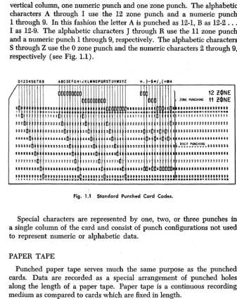
The punched card provides 80 vertical columns with 12 punching positions in each column. The 12 punching positions form 12 horizontal rows across the card. One or more punches in a single column represent a character. The number of columns used depends on the amount of data to be represented. The standard card code uses one or more of the 12 possible punching positions of a vertical column to represent a numeric, alphabetic, or special character. The 12 punching positions are divided into two areas, numeric and zone. The first 9 punching positions from the bottom of the card are the numeric punching positions and have an assigned value of 9, 8, 7, 6, 5, 4, 3, 2, and 1, respectively. The remaining 3 positions, 0, 11 (synonymously termed X), and 12, are the zone posi-tions. The 0 position is considered to be both a numeric and zone position.
The numeric characters 0 through 9 are represented by a single punch in a vertical column. For example, 0 is represented by a single punch in the 0 zone position of the column. A numeric 5 is represented by a single punch in the 5 position of the column.
The alphabetic characters are represented by two punches in a single
6 Introduction to Data Processing Systems
vertical column, one numeric punch and one zone punch. The alphabetic characters A through I use the 12 zone punch and a numeric punch 1 through 9. In this fashion the letter A is punched as 12-1, Bas 12-2 ... I as 12-9. The alphabetic characters
J
through R use the 11 zone punch and a numeric punch 1 through 9, respectively. The alphabetic characters S through Z use the 0 zone punch and the numeric characters 2 through 9, respectively (see Fig. 1.1).0123456789 A8CDEFGHIJKlMNOPQRSTUVWXYZ
/
0 00800
,.
11 11111
222 222222 2 33 3 3 3333333 330
H4H
.I
444444440 444 44
155151 5551II55ID 1111 III 166661& 666661&666 66666 6616 1171111 71171111117 111111 71111 1111'11 I I 11111111.11. 811.11. 111111
+.)-h/,(=tID*
000000
111111
222222 2 333333 3
444444 4
551551 I 616666 1 111111 7 111111
•
2 3 4 5 6 7
,
1
122$NEZONE PUNCHING 11- 2!1>NE _ 0810000000100000000 .nua ••• p • • • nnnMnan ••• 1 111111 1111111111111
'2 2222222222222222222 3 3333333333333333331
4 4444444444444444444
5 5 ~ D}~rJ .t!,~C.,H!N..G" 5 5 5 5 5 5 5 5 6 1666611861166666666 111711111177117111777
1 . , " ' , . , . , •••• , ••••
Fig. 1.1 Standard Punched Card Codes.
Special characters are represented by one, two, or three punches in a single column of the card and consist of punch configurations not used to represent numeric Or alphabetic data.
PAPER TAPE
Punched paper tape serves much the same purpose as the punched cards. Data are recorded as a special arrangement of punched holes along the length of a paper tape. Paper tape is a continuous recording medium as compared to cards which are fixed in length.
Reading or sensing paper tape is basically a process of automatically converting data recorded as holes to an electronic language and entering the data into the computer.
[image:25.435.50.388.62.488.2]Introduction to Data Processing Systems 7
The lower four channels of the tape (excluding the feed holes) are labeled 1, 2, 4, and 8; and are used to record numeric characters., The numeric characters 1 through 9 are represented as a punch or punches in these four positions and the character "0" is represented as a punch in the zero position. The sum of the positional values indicates the numeric value of the character. For example, a hole In channel I is used to represent a numeric 1; a combination of a 1 and 2 punch represents a numeric 3. The X and 0 channels are similar to the zone punches in cards. These channels are used in combination with the numeric channels to record alphabetic and special characters (see Figd.2).
TRACKS
IE.L.-x - I • • •
0 - • • • • • • • • • • • • •
CHrcK- • • • • • • • • • •
<.
••
• • • <•
•••••••
•
8 - • • • • • • • • • • FEIED- • • • • • • • • • • • • • -• • • • • • • • • • • • • • • • •
4 -
I... .... .... . ...
.
..
.
... .
2 - • • • • • • • • • • • • • • • •
1 - • • • • • • • • • • • • • • • • • •
••
•••
•
:
..
:
.:
".:
•
Fig. 1.2. < Character Coding for Eight-Channel Paper Tape.
To check that each character is recorded correctly, each column of the tape is punched with an odd number of holes. A check hole must be present in any column whose basic code (X, 0, 8, 4, 2, 1) consists of an even number of holes. Internal checking devices in the 1620 investigate each vertical array of punches to assure that this condition has been satisfied.
A punch in the ElL (end-of-line) channel is a specific function char-acter used to mark the end of a record on the tape. < The tape feed code consists of punches in the X, 0, C, 8, 4, 2, and 1 channels and is used to indicate blank character positions. A paper tape reader automatically skips over areas of tape punched with the tape feed code.
Figure 1.2 shows the 1~20 coding for all characters on an 8-channel paper tape.
COMPUTER CHARACTERISTICS
MACHINE CYCLES
8 Introduction to Data Processing Systems
a specific machine operation. The number of machine cycles required to execute a single instruction depends on the nature and function of the instruction.
SERIAL AND PARALLEL OPERATION
Computers are classified as either serial or parallel depending on the method the computer uses to perform arithmetic. Essentially, all arith. metic is performed by addition.
In a serial computer, numbers to be added are considered one position at a time (the units position, tens position, hundreds, and so on) in the same way that addition is done with paper and pencil. Whenever a carry is developed, it is retained temporarily and then added to the sum of the next higher order position.
The time required for serial operation depends on the number of digits in the factors to be added. Serial addition is shown in Table 1.1.
Table 1.1
1ST STEP 2ND STEP 3RD STEP 4TH STEP
Augend 1234 1234 1234 1234
Addend 2459 2459 2459 2459
Carry 1 1
Sum 3 93 693 3693
In a parallel computer, addition is performed on complete data words (a "word" is made up of two or more storage positions). The words are combined in one operation, including carries. Any two data words, regardless of the magnitude of the numbers contained in the words, can be added in the same time. Table 1.2 shows parallel addition.
Augend
Addend
Carry
Final Result
Table 1.2
00564213
00000824
1
[image:27.437.61.349.499.590.2]Introduction to Data Processing Systems 9
FIXED AND VARIABLE WORD LENGTH
"Fixed word length" and "variable word length" are terms used to describe the unit of data that can be addressed (referenced) and proc-essed by a computer system.
In fixed word length operation, information is handled and addressed in units or words containing a predetermined number of positions. The size of a word is designed into the system and normally corresponds to the smallest unit of information that can be addressed for processing in the central processing unit. Records, fields, characters, or factors are all manipulated in parallel as words.
In variable word length operations, data-handling circuitry is designed to process information serially as single characters. Records, fields, or factors may be of any practical length within the capacity of the storage unit. Information is available by character instead of by word.
Chapter
2
Introduction to the 1620
Data Processing System
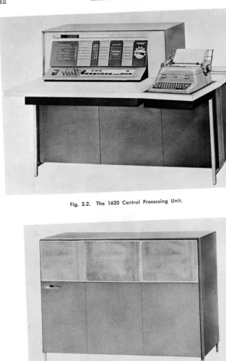
The 1620 Data Processing System (Fig. 2.1) is an electronic digital computer designed for technological and commercial applications. The heart of the system is the 1620 Central Processing Unit (Fig. 2.2) which houses the arithmetic and logical units, the magnetic core storage (20,000 positions), and the console panel and typewriter. The central processing unit is augmented by the 1622 Card Read-Punch and/or the 1621 Paper Tape Reader and the 1624 Paper Tape Punch, depending on whether the system is to process punched cards, paper tape, or both. Expansion of the basic system is possible by increasing the size of the magnetic core storage in increments of 20,000 positions until a maximum of 60,000 positions is reached (Fig. 2.3). A variety of special devices and additional instructions is available to increase the power and flex-ibility of the system.
Data and instructions entered into the system are placed in core storage as decimal digits. Each core storage position can be referred to individually and can store one digit of information. The addressing system provides for the selection of any digit or group of digits in stor-age. The 1620 can also process alphabetic characters and special char-acters such as $,
*, -,
+,
etc.The arithmetic and logical section of the computer is directed by the stored program. The 1620 has more than 30 different operations in its
12 Introduction to the 1620 Data Processing System
Fig. 2.2. The 1620 Central Processing Unit.
[image:31.458.67.394.48.570.2]Introduction to the 1620 Data Processing System 13
repertoire. Among these is a powerful set of branching instructions that make logical decisions based on the results of tests perfonned on a system of indicators and switches.
Addition, subtraction, and multiplication operations are perfonned by a table look-up method described in Chapter 4. Addition and multi-plication tables are stored in specified areas of storage and are auto-matically referred to when one of the arithmetic operations is being performed. Division is accomplished by a division simulating program
or by an automatic division feature.
The 1620 is a variable field computer in the complete sense of the term. Not only can data fields be of different lengths, but these same variable length fields can also be factors in all arithmetic operations without editing for size or position. Accuracy of results is insured by automatic internal checking that operates when data is being entered, read out, or processed by the system.
The console of the 1620 consists of control keys, switches, indicator panel, and typewriter. The control keys and switches are used for man-ual or automatic operation of the system. The console panel provides a visual indication of the status of various registers and control circuitry . within the computer. The typewriter is used as an output device, for direct entry of data and instructions into core storage, and for pennanent logging of the operator's intervention during the execution of a program. Information is entered into the system by the input devices: the 1621 Paper Tape Reader, the 1622 Card Read-Punch, and the typewriter. Eighty-column cards are read at the rate of 250 cards per minute. The paper tape reader reads an 8-channel paper tape at the rate of 150 char-acters per second. Speed of typewriter infonnation entry depends upon the operator's ability.
The recording of processed information is accomplished by the output devices; the 1622 Card Read-Punch, the 1624 Paper Tape Punch, and the typewriter. Cards are punched at the rate of 125 80-column cards per minute; the tape punch punches information in an 8-channel. paper tape at the rate of 15 characters per second; and the typewriter types at the rate of 10 characters per second.
Program preparation is simplified by the use of two major program-ming systems. These are the Symbolic Programprogram-ming System (SPS) and Fortran (from "formula translation"), both of which will be discussed in detail.
SPS, which simplifies program writing by reducing the clerical work involved, assembles a program written in mnemonic or symbolic nota-tion by converting the symbols to machine language instrucnota-tions and assigning locations in core storage for both data and instructions.
state-14 Introduction to the 1620 Data Processing System
ments into a complete machine language program, generating the step-by-step instructions necessary to solve the problem. A program written in Fortran for the 1620, after minor modifications, can also be translated and executed on other computers such as the IBM 7090, 1401, and many others.
INTERNAL DATA REPRESENTATION
DIGITS
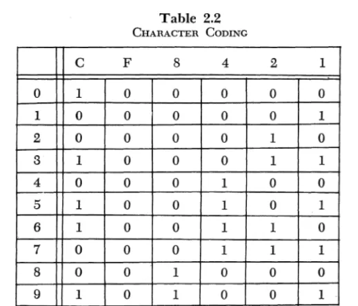
Each core storage position in the 1620 has a unique address and can store one digit of information. Each digit is in a binary coded decimal (BCD) form represented by a 6-bit numeric code. In this code, six posi-tions of binary notation (0 or 1) are used and each of these posiposi-tions is called a bit (binary digit). Each position has one of two conditions: either a bit is present represented by a ''1'' or it is not present represented by a "0." The six positions are divided into three groups: one check bit (C bit), one flag bit (F bit), and four numeric bits with the assigned values of 8, 4, 2, and 1 (table 2.1).
Table 2.1
CHECK FLAG
BIT BIT NUMEmcAL BITS
C F 8 4 2 1
The value of a decimal digit is the sum of the bits present in the numeric portion of the 6-bit code. Only bit combinations whose sum is 9 or less are used. Using the notation that a "1" indicates the presence of a bit and a "0" indicates the absence of a hit, we would represent the decimal digit 6 as 0110 considering only the numeric positions. The digit 8 is represented as 1000.
Introduction to the 1620 Data Processing System 15
6-bit numeric code and the check bit is automatically added if it is required. The flag bit, to be discussed shortly, is counted in parity checking. The check bit alone represents the digit O.
Table 2.2 shows the 6-bit numeric coding of the decimal digits 0 through 9.
C F
0 1 0
1 0 0
2 0 0
3 1 0
4 0 0
5 1 0
6 1 0
7 0 0
8 0 0
9 1 0
Table 2.2
CHARACTER CODING
8 4
0 0
0 0
0 0
0 0
0 1
0 1
0 1
0 1
1 0
1 0
The flag bit is used in three ways:
2 1
0 0
0 1
1 0
1 1
0 0
0 1
1 0
1 1
0 0
0 1
1. Field Definition: The high-order position of a numeric field is defined by the presence of a flag (the terms "flag" and "flag bit" are used synonymously). Thus the number 537 would appear in storage with a flag bit in the core position containing the 5. A flag is denoted by a horizontal line above a digit, 537.
2. Sign Control: The presence of a flag in the units position of a nu-meric field indicates that the field is negative. If no flag is present in the units position of a field, the field is taken to be positive. The number -537 would appear in storage as
537.
[image:34.438.70.330.133.355.2]16 Introduction to the 1620 Data Processing System
A numeric blank has C-8-4 coding. It is used for the control of blank columns when cards are being punched, and, like the record mark, can-not be used in arithmetic operations. Unlike the record mark, it may can-not even be present in an instruction.
Alphabetic information is represented in the computer in a double-digit form. Two core storage locations are required to represent one alphamerical character. The two digits are referred to as the zone digit and the numerical digit. The two digits representing one alphamerical character must be located in adjacent core positions, and the zone digit must always occupy an even-numbered core position.
Table 2.3 shows the double-digit representation of all the alphameric characters.
Table 2.3
ALPHAMERIC DATA REPRESENTATION
~
zone Digitf
NUmeriCal Digitr-
Character0*
00 b (blank)*
03
04 )
10
+
13 $
14
*
20
21 /
23
24
33
=
34 @
41 A
42 B
43 C
44 D
45 E
46 F
47 G
48 H
49 I
50
0
51
J
52 K
r
>?:one Digitr
Numerical Digitr-
Character53 L
54 M
55 N
56 0
57 P
58 Q
59 R
62 S
63 T
64 U
65 V
66 W
67 X
68 Y
69 Z
70 0
71 1
72 2
73 3
74 4
75 5
76 6
77 7
78 8
Introduction to the 1620 Data Processing System 17
FIELDS
A field consists of a number of consecutive digits which are considered as a group in arithmetic and internal data transmission instructions. A field is always addressed (referenced) by its low-order digit, which oc-cupies the highest numbered core storage position of the field. A field is processed serially from right to left into successively lower core stor-age positions until a digit with a flag is sensed. The digit with the flag is treated as part of the field, but no more digits are processed.
The absence of a flag in the low-order position of a field (the addressed digit) is unconditionally interpreted as a positive field of data.
One-digit fields of data are not allowed. The smallest allowable data field is two digits.
Figure 2.4 illustrates the processing of a field.
- - - F i e l d - - - - l
X X X
t
Direction Processedt
Flag Bit Addressed Digit
(End of Field) (low-Order Position of Field)
Fig. 2.4. Field Processing.
RECORDS
A record consists of a field or fields of data related to input-output operations. A record is addressed at its high-order digit, which occupies the lowest core storage position of the record. Records are processed
Record Mark Record Mark
~~x
J,.1d 0
Xr
0J"1d 0
XI
X
~fi'ld~
i
X X~---Record---""
•
Arrows Indicote Direction of Processing
18 Introduction to the 1620 Data Processing System
serially from left to right (high-order to low-order digits). A record mark (:I:) defInes the end of a record and is located in the highest num-bered core location.
Figure 2.5 illustrates the processing of a record as compared to the processing of a fIeld.
NUMERICAL AND ALPHAMERICAL MODES
The input-output instructions of the 1620 cause data to be read or written in either a numerical or alphamerical mode. The 1620 has no way to determine if an element entering the system is being entered as numeric data or alphabetic data unless the appropriate mode is indicated in the input-output instruction.
In the numeric input mode each character read in is represented in storage by one decimal digit. Alphabetic and special characters will not enter storage correctly as they require a double-digit representation.
Only the record mark (t), numeric blank, and the digits 0 through 9
will be represented in storage correctly. In the numeric output mode each character in storage is represented as a single character on the output medium. Data in storage in the double-digit code will not be converted to its single character representation.
In the alphameric input mode each input character is automatically converted to its double-digit representation and is stored in memory as two decimal digits. In the alphameric output mode the double-digit representation of data is automatically converted to single characters which are then written on the output medium.
MAGNETIC CORE STORAGE
The storage medium utilized by the 1620 Data Processing System is magnetic core storage. A magnetic core is a tiny ring of ferromagnetic material a few hundredths of an inch in diameter. The outstanding characteristic of the core is that it can be easily magnetized, and, unless deliberately changed, it retains its magnetism indefInitely.
Many of these cores are strung on a screen of wires to form what is called a core plane (Fig. 2.6).
By sending half the amount of current necessary to magnetize a core
Introduction to the 1620 Data Processing System
~1/2 Current
~ ,~~ ',i
Fig. 2.6. A Standard Core Plane.
19
Cores then can be controlled in two ways: by selecting a specific pair of wires, we can decide which core is to be affected; and by controlling
the direction of current How, we can determine whether it is to be
posi-tively or negaposi-tively magnetized. We can now adopt a convention and say that when a core is positively magnetized it is "on" or contains a bit. If a core is negatively magnetized it is "off" and does not contain a bit.
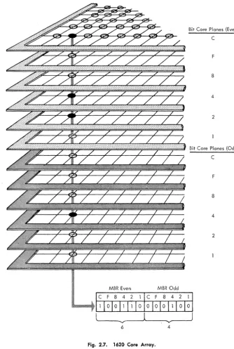
If we stacked six core planes vertically so that a vertical column con-tained six cores, we could represent the' 6-bit numeric coding used by the 1620 for internal data representation. Each of the six core planes assumes a specific value-one plane would be the C-bit plane, another plane would be the F-bit plane, and another plane would be the 8-bit plane, etc. Thus six vertical cores form a core storage position and can represent any decimal digit through the 6-bit numeric code signified by the status of the cores (positive or negative).
In the 1620, core storage is made up of 12 core planes. Thus one vertical column contains two core storage positions. The top six core planes represent all the even-numbered addresses, and the bottom six core planes represent all the odd-numbered core addresses. Figure 2.7 shows the core array in the 1620.
ad-20 Introduction to the 1620 Data Processing System
MBR Even
Bit Core Plones (Even)
C
F
8
4
2
Bit Core Planes (Odd)
C
F
8
4
2
~---.'V
__
- - J6 4
[image:39.437.59.394.66.564.2]Introduction to the 1620 Data Processing System 21
dressed, the MBR would again receive the digits from core positions 00500 and 00501.
Chapter
3
Basic Programming Concepts
Contrary to some popular belief, the digital computer is not a "brain." It does not yet possess the intelligence to think. The computer can do nothing of its own volition, but must rely upon instructions supplied by humans to perform a given task. Thus a communication between man and computer is necessary. This communication takes the form of a set of formal instructions with which we command the computer and to which the computer responds. Once the computer has received its instructions, it can perform its task at speeds measured in microseconds. The combination of the human thought process and the fantastic speeds at which computers operate form a powerful tool for industry and re-search.
Chapters 5 through 9 are devoted to a complete detailed description of all basic 1620 instructions. These instructions fall into five general categories:
1. Arithmetic
2. Internal Data Transmission 3. Branch
4. Input-Output 5. Miscellaneous
The 1620 digital computer utilizes a 12-digit instruction which is divided into three parts: a 2-digit operation (OP) code, a 5-digit P address (P Operand), and a 5-digit Q address (Q Operand). Each of the 12 digits making up an instruction is assigned a unique notation so that easy
Basic Programming Concepts 23
reference may be made to any part of an instruction. The two digits forming the operation code will be referenced as 00 and 01 , The five digits comprising the P address will be referenced as P2 , Pa, P4 , P5, and P6 • Similarly, the five digits comprising the
Q
address will be referenced as Q7, Qs, Q9, QI0, and Qll'Fig. 3.1 illustrates the format of a 1620 instruction.
00
J
01 P21 PaI
P4I
P5I
P6 Q7I
QsI
Q9I
QlOI
QllOP
P Address Q AddressCode
Fig. 3.1. Instruction Format.
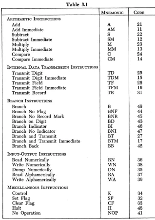
The 2-digit operation code specifies which operation is to be executed. Table 3-1 is a chart of all basic 1620 operation codes and their associated mnemonics. Mnemonics refer to the alphabetic representation of opera-tions codes used in the symbolic programming system (see Chapter 11).
The 5-digit P operand has many functions, depending on the instruc-tion. It may represent the core location (1) that data is transmitted to,
( 2) that data is transmitted from, (3) that the program branches to, or ( 4) of data to be processed.
Likewise, the
Q
operand has many functions, depending on theinstruction. It may represent (1) the address from which data is trans-mitted, (2) the input-output device that is employed, (3) the address of data to be processed, or (4) the indicator that is interrogated.
The 1620 has an extremely powerful and flexible instruction repertoire. Certain arithmetic and internal data transmission instructions are labeled
immediate. These instructions use part of the instruction itself as a data field. The low-order position of the data field is the Qll position of the instruction itself. The immediate instructions greatly facilitate pro-gramming and conserve storage locations by storing constants as part of instructions.
The instructions that direct the 1620 are stored in the magnetic core
memory of the computer. The high-order digit (00) of an instruction
must be located in an even-numbered core position. This restriction is
imposed by the workings of the internal circuitry of the computer, with which we will not concern ourselves at this time. Suffice it to say that this restriction is easily complied with.
An instruction is referenced by the core location of its high-order digit
(00 ), Thus if we refer to the instruction at core location 00012, the
24 Basic Programming Concepts
Table 3.1
MNEMONIC CODE ARITHMETIC INSTRUCTIONS
Add A 21
Add Immediate AM 11
Subtract S 22
Subtract Immediate SM 12
Multiply M 23
Multiply Immediate MM 13
Compare C 24
Compare Immediate CM 14
INTERNAL DATA TRANSMISSION INSTRUCTIONS
Transmit 'Digit TD 25
Transmit Digit Immediate TDM 15
Transmit Field TF 26
Transmit Field Immediate TFM 16
Transmit Record TR 31
BRANCH INSTRUCTIONS
Branch B 49
Branch No Flag BNF 44
Branch No Record Mark BNR 45
Branch on Digit BD 43
Branch Indicator BI 46
Branch No Indicator BNI 47
Branch and Transmit BT 27
Branch and Transmit Immediate BTM 17
Branch Back BB 42
INPUT-OUTPUT INSTRUCTIONS
Read Numerically RN 36
Write Numerically WN 38
Dump Numerically DN 35
Read Aiphamerically RA 37
Write Aiphamerically WA 39
MISCELLANEOUS INSTRUCTIONS
Control K 34
Set Flag SF 32
Clear Flag CF 33
Halt H 48
No Operation NOP 41
The 1620 uses a 2-address instruction system. During normal operation,
program instructions are executed sequentially. For example, if we
[image:43.437.72.390.61.512.2]Basic Programming Concepts 25
In a address system both addresses may reference data. The 2-address system is in contrast to a 1-over-1 2-addressing system, in which part of the instruction itself is used to indicate the location of the instruc-tion to be executed next. The 2-address system is, in many ways, a much more powerful and flexible programming system.
In the discussion of the functions of the Q address, it was mentioned
that indicators may be interrogated. The 1620 has internal machine indi-cators to facilitate the decision-making ability of the computer. The three indicators of greatest importance are the following:
1. High Positive (HIP). The High Positive indicator is turned on if the
result of an arithmetic operation is positive and not zero.
2. Equal/Zero (E/Z). The Equal Zero indicator is turned on if the
result of an arithmetic operation is zero.
3. Overflow. The Overflow indicator is turned on if certain overflow
conditions exist.
A more detailed discussion of the on-off status of the indicators is made in the chapter on arithmetic instructions.
As each instruction is discussed, a formula for computing execution time will be given. The following abbreviations are used.
Dp
=
Number of digits, including high-order zeros, in the field at the P address.Dq
=
Number of digits, including high-order zeros, in the field at theQ address.
De
=
Number of positions compared prior to detection of a digit other than zero.'Rq
=
Number of digits, including the record mark, in the record at theChapter
4
The Algorithms of Arithmetic
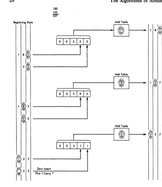
The heart of the hand calculator is the accumulator unit, which oper-ates on the principle of the toothed gear. Addition is usually accomplished by rotating the gear in one direction. As the gear reaches a maximum position it flips an adjacent gear. In this way carries are propagated in the addition process. Subtraction· is accomplished by rotating the gear in a direction opposite to that of addition. Multiplication can be con-sidered as successive addition, and division as a process of iterative subtraction. The 1620 has no accumulator and does not operate on the principle of the toothed gear. Consequently, an alternate method of performing the basic functions of mathematics must be used. The basic operations of the 1620 are addition and multiplication, and certain areas of core storage are reserved for addition and multiplication tables. These operations are done serially, digit by digit, and the computer "looks up" the result of an operation in these tables. Subtraction utilizes the addition table but prepares the subtrahend digit before entry into the addition table. This preparation takes the form of tens or nines complementation. The process of division is discussed in a special chapter.
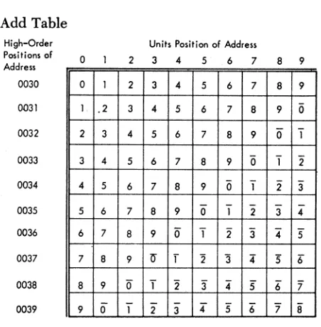
The addition table occupies core positions 00300-00399 (see Table 4.1). Looking at this table, the reader will notice that the number 7 appears at the following 8 locations: 00307, 00316, 00325, 000334, 00343, 00352,
00361, and 00370. The reader will also notice that a flagged 7
(7)
appears at core positions 00389 and 00398.
You have probably noticed that the sum of the digits in the units and tens positions of the address is the digit located in that core position.
[image:45.440.58.395.59.276.2]The Algorithms of Arithmetic
Add Table High-Order Positions of Address 0030 0031 0032 0033 0034 0035 0036 0037 0038 0039 o
0 1
1. .2
2 3
3 4
4 5
5 6
6 7
7 8
8 9
9 0
27
Table 4.1
Units Position of Address
2 3 4 5 6 7 8 9
2 3 4 5 6 7 8 9
3 4 5 6 7 8 9 0
4 5 6 7 8 9 0" "1 5 6 7 8 9 0 "1 2
6 7 8 9 0 "1 2 "3
7 8 9 0 1 2 3 4
8 9 0" T 2 3" 4" 5 9 if f "2 '3 4 :5 6"
0 T 2" "3 4" 5 6" '7 1 2 3 4" 5 6" '7 8
It is also obvious in the case of the two flagged 7's that the flag is present for the purpose of propagation of carries. Addition is accomplished in the 1620 by literally attaching data digits to a machine-generated address of 003XX to form a 5-digit add table address. The answer is then "looked up" in the add table.
As a further example note that the sum of the digits 4 and 2 is found at table address 00342 or 00324.
The addition of two numbers that generates a carry-over produces the following result: the addition table address generated by the adjacent digits will be increased by 1.
If a field containing n digits is added to a field containing n
+
k digits(k>O), k zeros are inserted automatically to make the fields of equal length. These zeroS are inserted one at a time by internal circuitry of the 1620. They do not alter the field permanently. (See Fig. 4.1.)
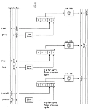
The process of subtraction is almost identical with that of addition. That is, an address of 003XX is generated with the data digits supplying the missing positions of the address. However, the subtrahend digit is inserted in the look-up address in its tens complement form on the first cycle and in its nines complement form thereafter. If the addition table yields a flagged digit, the address generated by the contiguous digits will be increased by 1 (see Fig. 4.2).
[image:46.432.92.318.75.305.2]28
185
+52
~
Beginning Doto
~\Ik
1 8~5= ---~ ?f~\'
I I
5t~ ---~
7~\\'I ,
Plus 1 Carry *
The Algorithms of Arithmetic
·1
Add Table,'\\l/jy
""7-1/j\~
Add Table ~\I~
1~~
I I
•
1 8N%7!~
Fig. 4.1. Schematic Diagram of Add Operation.
to be multiplied into a table address. The multiplication table, which occupies core locations OOl()()""()0299 (see Table 4.2), does not yield as obvious an algorithm as did the addition process.
[image:47.436.41.369.43.420.2]The Algorithms of Arithmetic
Beginning Data
185
- 52
133 Add Table
-~
-~
(Units)
I 8
(Ttl~ ,Iii,_________
--.J 5:ot':
"/11\
(Units)
(Ten.)
(Tens)
,III,
(Hunci,ed.) "I '" 3 3
111\\
I I
(Hunci,ed.) :,11/". 5 2
1'-1"1
Fig. 4.2.
[image:48.433.51.354.52.424.2]Add Table
...
. ... I ] f l
-~
+1 for carry from previous cycle
Schematic Diagram of Subtract Operation.
29
number is incremented by 1 and is then routed to the hundreds digit of the base address being formed. The units digit of the doubler's effort is routed to the units digit of the base address, and this completes the construction of the multiplication table look-up address.
30
Multiply Table
High-Order Positions of Address 0010 0011 0012 0013 0014 0015 0016 0017 0018 0019 0020 0021 0022 0023 0024 0025 0026 0027 0028 0029 o 0 0 0 0 0 0 0 0 0 0 0 5 0 5 0 5 0 5 0 5 0 0 0 0 0 0 0 0 0 0 0 0 1 1 2 2 3 3 4 4
The Algorithms of Arithmetic
Table 4.2
Units Position of Address
2 3 4 5 6 7 8 9
0 0 0 0 0 0 0 0
1 0 2 0 3 0 4 0
2 0 4 0 6 0 8 0
3 0 6 0 9 0 2 1
4 0 8 0 2 1 6 1
5 0 0 1 5 1 0 2
6 0 2 1 8 1 4 2
7 0 4 1 1 2 8 2
8 0 6 1 4 2 2 3
9 0 8 1 7 2 6 3
0 0 0 0 0 0 0 0
6 0 7 0 8 0 9 0
2 1 4 1 6 1 8 1
8 1 1 2 4 2 7 2
4 2 8 2 2 3 6 3
0 3 5 3 0 4 5 4
6 3 2 4 8 4 4 5
2 4 9 4 6 5 3 6
8 4 6 5 4 6 2 7
4 5 3 6 2 7 1 8
To the novice, this may seem like a good deal of wind and very little storm. Popular belief may lead one to the idea that the computer is intelligent enough to add 2 and 3, or multiply 5 and 6, without extensive coaching. Unfortunately, in the present state of computer development, the thinking machine is semifantasy, semifiction.
[image:49.435.91.353.58.493.2]The Algorithms of Arithmetic
(Multipliccnd) (Multiplier)
(Units)
(Units)
(Units)
(Tens)
(Tens) 12 12 144
Multiply Table
00
"'\1/"~---~_. ~04~ ~. - - - -__
?III~'"
31
Product Area
o 4
Multiply Tabte
r---;.~~~---~_
0 0 2 4~
o 0 4 4
o 1 4 4
1 4 4
Fig. 4.3. Schematic Diagram of Multiply Operation.
[image:50.433.42.365.62.522.2]32 The Algorithms of Arithmetic
Chapter
5
The Arithmetic Instructions
Fundamentally, a computer is a calculator. Hence, the instructions that perform arithmetic are among the most important in the repertoire of commands. This chapter deals only with those arithmetic instructions that are common to all 1620's. Divide commands, which are not neces-sary for a machine installation, are discussed in a later chapter. Special division-simulating programs perform this operation in a variety of ways: successive subtraction; approximation of a reciprocal by series, followed by a multiplication; etc. The statement that "divide commands are not necessary" does not imply that one may not divide with the 1620. Circuitry, which performs division under command, may not be present in some machines, in which case one must resort to division simulators called division subroutines. The choice to have division command circuitry is made at each machine installation, and such a choice is generally made with consideration of two factors: necessity and funds. The difference between subroutine divide and command circuitry is only one of speed, not accuracy.
Although speed of calculation is not the only factor under considera-tion when one undertakes a computer survey, it is an extremely critical one. The reader will notice that all timings of operations are given in microseconds. It is this remarkable speed factor that makes a com-puter so valuable.
---~---Instruction: Add
Operation Code: 21
Symbolic Name: A
Description:
The datal that is located at the Q address (Q field data) is added to the data that is located at the P address (P field data): The sum
I Unless otherwise specified, the term "data" refers to a single item.
34 The Arithmetic Instructions
replaces the P field data. The Q field data remains unchanged. A zero sum retains the sign of the P field data. A sum other than zero retains the sign of the larger valued field. If the number of digits in the Q field data is less than the number of digits in the P field data, high-order zeros are internally generated to make the fields of equal length. The generated zeros do not alter the Q field data.
The addition process is terminated by the sensing of the Hag over the . high-order digit of the P field data. The algebraic sign of the result is indicated by the presence or absence of a Hag in the units position of the P field data after termination of the operation.
A correct answer may not be developed if the number of digits in
the Q field data exceeds the number of digits in the P field data. Only the number of digits in the Q field data equal to the number of digits in the P field data is used in developing the result. An invalid addition is always obt