Optimization of Single Phase E-Core Hybrid Excitation Flux Switching
Machine
Siti Nur Umira Zakaria
a,Erwan Sulaiman
b,and Mohamed Mubin Aizat
Department of Electrical Power Engineering, UniversitiTun Hussein Onn Malaysia, Locked Bag 101, BatuPahat, Johor, 86400 Malaysia
a
[email protected], [email protected]
Keywords:Hybrid excitation flux switching machine (HEFSM), flux switching machine (FSM), single phase.
Abstract. Research and development on hybrid excitation flux switching machines (HEFSM) for
various applications have been carried out in the last years. The designed HEFSM consist of permanent magnet (PM) and DC field excitation coil (DC-FEC) which is located on the stator core as their main flux sources, while a single piece rotor gives the advantages of robust rotor structure. Since most of the designed HEFSMs utilize three-phase windings, more complicated design and control system are required to run the motor. Thus, a new design of single-phase E-Core HEFSM with several advantages of much simpler converter size and smaller battery package due to small voltage capacity when compared with conventional three-phase system is proposed. Consequently, the size of overall configuration systems will also be reduced resulting in reducing total weight and cost. In this paper, initial performances of 4S-4P, 4S-6P, 4S-8P and 4S-10P E-Core HEFSM topologies are analysed. Since 4S-10P design gives highest torque and power performances, deterministic design optimization approach is conducted to enhance much higher and optimum performances. As conclusion, the optimized E-core HEFSM with 4S-10P topology has achieved maximum torque and power of 208.857Nm and 47.31 kW, respectively.
Introduction
In the mid-1950s, the first concept of flux switching machine (FSM) has been founded and published. A single-phase permanent magnet (PM) FSM with limited angle actuator or more well-known as Laws relay, having 4 stator slots and 4 rotor poles (4S-4P) has been developed [1], and has been extended to a single phase generator with 4 stator slots, and 4or 6 rotor poles (4S-4/6P) [2]. Over the last ten years, many novel and new FSMs topologies have been proposed for various applications, ranging from low cost domestic appliances, automotive, wind power, aerospace, and traction drive applications, etc. In general, FSMs can be categorized into three groups that are field excitation (FE) FSMs, permanent magnet (PM) FSMs and hybrid excitation (HE) FSMs. Both PMFSMs and FEFSMs have only PM and DC-FEC, respectively as their main flux sources, while HEFSMs combines both PM and DC-FECs [3-4] where the advantages of both PM machines and DC-FEC synchronous machines are combined. As such, HEFSMs have the potential to improve flux weakening performance, high power and torque density, variable flux capabilities, and high efficiency which have been investigated extensively over many years [5-7].
Operating principle of single phase E
The operating principle of the
E-from the stator to the rotor switches its polarity following the rotation of rotor. At one instant, half of rotor poles receive the flux from the stator while another half of rotor poles bring the flux to the stator to make a complete flux cycle. The operating principle and definition of flux switching can be described either by changing flux in the stator or chan
both PM and FEC fluxes are in the same polarity, both fluxes are combined and move together into the rotor, hence producing more fluxes with a so called hybrid excitation flux
single phase E- Core HEFSM, the conceivable
) 2 1 ( q k N
Nr = s ±
where Nr is the number of rotor poles
the natural number is defined as k. For the proposed motor, Nr is set as 4, 6, 8 and 10.
Design Parameter and Procedures
Fig. 2 represents the torque and power comparisons of 4S-6P, 4S-8P and 4S-10P topologies.
10P and 4S-8P designs, the initial power obtained is still far from target power of 41kW. The maximum power obtained for 4S
parameter and design optimization process
conducted in effort to meet the target performance. The first step is carried out by updating rotor parameters, D1, D2 and D3 while keeping D6 to D9 constant. Since the torqu
increasing rotor radius, D1 is firstly
characteristic at various D1, D2 and D3 in p.u. From the figure, the torque is maximized when radius of rotor is 90mm. Then, the rotor p
(a)
Fig. 1: Initial design of 1-phase E
Fig. 2: Comparision of torque and power at various topologies 47.25 0 40 80 120 160 200 4S-4P T[Nm]P[kW]
Operating principle of single phase E-Core HEFSM
-Core HEFSM is similar with conventional FSM. The flux flows from the stator to the rotor switches its polarity following the rotation of rotor. At one instant, half of tor poles receive the flux from the stator while another half of rotor poles bring the flux to the stator to make a complete flux cycle. The operating principle and definition of flux switching can be described either by changing flux in the stator or changing flux in the rotor. Since the direction of both PM and FEC fluxes are in the same polarity, both fluxes are combined and move together into the rotor, hence producing more fluxes with a so called hybrid excitation flux [8].
conceivable number of rotor pole and stator slot is defined by (1)
number of rotor poles, Ns is the stator slots number, q is the number of phases and . For the proposed motor, q is set as single phase, N
Design Parameter and Procedures
torque and power comparisons of single phase E-Core HEFSM for 4S logies. While the target torque of 101Nm has been achieved for 4S 8P designs, the initial power obtained is still far from target power of 41kW. The maximum power obtained for 4S-10P E-Core HEFSM is approximately 26kW hence design
design optimization process demonstrated in Fig. 3 and Fig. 4 correspondingly conducted in effort to meet the target performance. The first step is carried out by updating rotor parameters, D1, D2 and D3 while keeping D6 to D9 constant. Since the torqu
rotor radius, D1 is firstly updated as the main variable parameter. Fig. 5 shows the torque characteristic at various D1, D2 and D3 in p.u. From the figure, the torque is maximized when rotor is 90mm. Then, the rotor pole depth D2 and rotor pole width D3 are updated while
(b) (c) (d)
phase E-Core HEFSM (a) 4S-4P (b) 4S-6P (c) 4S-8P (d) 4S
Fig. 2: Comparision of torque and power at various topologies 107.6
132.26
182.02
6.2 9.65 10.42 26
4P 4S-6P 4S-8P 4S-10P
E-Core HEFSM design Torque Power
Core HEFSM is similar with conventional FSM. The flux flows from the stator to the rotor switches its polarity following the rotation of rotor. At one instant, half of tor poles receive the flux from the stator while another half of rotor poles bring the flux to the stator to make a complete flux cycle. The operating principle and definition of flux switching can be ince the direction of both PM and FEC fluxes are in the same polarity, both fluxes are combined and move together into . In the proposed number of rotor pole and stator slot is defined by (1)
(1)
is the number of phases and is set as single phase, Ns is set as 4 and
Core HEFSM for 4S-4P, the target torque of 101Nm has been achieved for 4S-8P designs, the initial power obtained is still far from target power of 41kW. The
Core HEFSM is approximately 26kW hence design correspondingly are conducted in effort to meet the target performance. The first step is carried out by updating rotor parameters, D1, D2 and D3 while keeping D6 to D9 constant. Since the torque increases with variable parameter. Fig. 5 shows the torque characteristic at various D1, D2 and D3 in p.u. From the figure, the torque is maximized when ole depth D2 and rotor pole width D3 are updated while
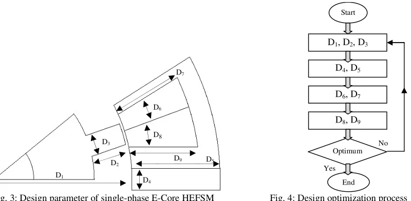
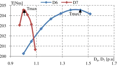
keeping D1 constant which bring out the highest torque and power capability. As a result, the optimum torque condition is achieved when combination of both D2 and D3 are at 30mm and 17mm, respectively. Using the maximum torque and power determined from combination of D2 and D3, the second step is carried out by updating the PM slot parameter. Based on the optimization process, D4 and D5 will only produce maximum torque and power when D1 is varied. The optimization process is continued by verifying DC-FEC slot parameter D6 and D7 while keeping other parameters constant. The maximum torque is obtained when D6 is 18mm while middle stator tooth, D7 is 33mm as depicted in Fig. 6. Then, by using the combination of D6 and D7 that bring out the optimum torque and power at the third step, the final step is carried out by varying armature coil slot parameters, D8 and D9 with keeping other parameters discussed above constant. The necessary armature coil slot area, Sa is determined by varying armature coil depth, D8 and E-Core stator teeth D9 to accommodate integer number of turns, Na for armature coil slot. Fig. 7 represents torque performance of single-phase 4S-10P E-Core HEFSM at various stator teeth, D8 and various armature coil depth, D9 in p.u. After one cycle optimization is conducted, the proposed motor with PM volume of 1.3kg has achieved optimum performance of 208.86Nm with maximum power of 49.31kW.
Performance of Improved Design Single Phase E-Core HEFSM
The drive performance of the improved design 4S-10P E-Core HEFSM in term of torque against DC-FEC current density, Je at various armature current density conditions, Ja is observed as shown in Fig. 8. At Ja of 5Arms/mm2, 10 Arms/mm2, 15Arms/mm2 and 20Arms/mm2 it is noticeable that, the average torque is increased with increasing Je until certain value of Je but starts to decrease when higher Je is injected to the system. Based on examination of magnetic flux density distribution, it is found that, flux at higher Je cancels the armature flux thus reducing the torque generation.
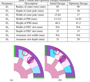
Furthermore, comparisons between torque and power versus speed curves of the improved and initial design motor are plotted in Fig. 9. In the figure, the blue and red lines depict the maximum torque curve for the designated operating speed of the improved and initial design E-Core HEFSM for comparison. The maximum torque obtained for the improved and initial designs at base speed of 1096r/min and 967r/min are 209.85Nm and 182.02Nm, respectively. The plot clearly shows that the improved design has better torque characteristic and produced much higher torque at high speed region when compared with the initial design. In addition, the maximum power obtained from the improved design motor is 49.21kW which successfully achieved 20% higher than the target power. The comparison between initial and optimized design that meet the highest torque and power is shown in Fig. 10 while the detail parameters are listed in Table I.
[image:3.612.95.495.68.264.2]
Fig. 3: Design parameter of single-phase E-Core HEFSM Fig. 4: Design optimization process D8, D9
End D6, D7
No
Yes Optimum
D4, D5
D1, D2, D3
Start
D9 D7
D1
D3
D2
D8
D5 D6
Conclusion
In this paper, design optimization and performance analysis of 4S-10P E-Core HEFSM with 1.3kg PM volume has been presented. Design optimization using deterministic design approach to bring out the optimum performances of the proposed machine has been clearly demonstrated. In conclusion, the torque and power of the optimum design single-phase 4S-10P E-Core HEFSM have been increased approximately 15% and 89% more than the initial design.
Acknowledgement
This research was supported by ERGS (Vot E030), Ministry of Higher Education Malaysia (MOHE).
References
[1] Laws AE. An electromechanical transducer with permanent magnet polarization, Technical Note No.G.W.202, Royal Aircraft Establishment, Farnborough, UK (1952).
[image:4.612.312.517.71.187.2]Fig. 5: Torque versus D1, D2, D3 characteristic Fig. 6: Torque versus D6, D7characteristic
Fig.7: Torque versus D8, D9characteristic Fig. 8: Torque versus Je characteristic
Fig. 9: Torque and power versus speed characteristic 175
180 185 190 195 200 205
0.9 1 1.1 1.2 1.3
T[Nm]
D1, D2, D3[p.u]
D1 D2 D3
200 201 202 203 204 205
0.9 1.1 1.3 1.5 1.7
T[Nm]
D6, D7[p.u]
D6 D7
202 204 206 208 210
0.8 0.9 1 1.1 1.2 1.3
T[Nm]
D8, D9[p.u]
D8 D9
0 50 100 150 200 250
0 5 10 15 20 25 30
T[Nm]
Je[A/mm2]
JA=5 JA=10 JA=15
JA=20 JA=25 JA=30
0 10 20 30 40 50 60
0 50 100 150 200 250
0 2000 4000 6000 8000 10000 12000 Power[kW] T[Nm]
Speed[r/min] Torque-Improve Torque-Initial Power-Improve Power-Initial Tmax
Tmax
Tmax Tmax
Tmax
Tmax
Tmax
[image:4.612.90.515.226.336.2][2] Rauch SE, Johnson LJ. “Design principles of flux-switching alternators,” AIEE Trans. (1955) 1261-1268.
[3] E. Sulaiman, T. Kosaka and N. Matsui, “FEA-based design and parameter optimization study of 6-slot 5-pole PMFSM with field excitation for hybrid electric vehicle,” Power and Energy (PECon), IEEE International Conference. (2010) 206-211
[4] E. Sulaiman, T. Kosaka, N. Matsui and M. Z. Ahmad, “Design Improvement and Performance Analysis of 12Slot-10Pole Permanent Magnet Flux Switching Machine with Field Excitation Coils,” International Power Engineering and Optimization Conference (PEOCO). (2011)
[5] Y. Amara, L. Vido, M. Gabsi, E. Hoang, M. Lecrivain, and F. Chabot: “Hybrid Excitation Synchronous Machines: Energy Efficient Solution for Vehicle Propulsion”, IEEE Vehicle Power and Propulsion Conference, (2006) 1-6, Sept. 2006
[6] C. Zhao, and Y. Yan: “A Review of Development of Hybrid Excitation Synchronous Machine”, Proc. of the IEEE International Symposium on Industrial Electronics, (2005) 857-862
[7] R. L. Owen, Z.Q. Zhu, and G.W. Jewell: “Hybrid Excited Flux-switching Permanent Magnet Machines”, Proc. 13th European Conf. on Power Electronics and Applications, EPE, Barcelona, Spain, (2009) 1-10
[8] S.N.U.Zakaria and E. Sulaiman, “Performance Analysis of E-Core Hybrid Excitation Flux Switching Motor for Hybrid Electric Vehicles,”IEEE International Power Engineering and Optimization Conferences (2014)
Table I: Initial and Optimize Design Parameters
Parameter Description Initial Design Optimize Design D1 Radius of outer rotor (mm) 85 90
D2 Depth of rotor pole (mm) 25 30
D3 Width of rotor pole (mm) 15.84 17
D4 Width of PM (mm) 13.311 14.93
D5 Height of PM (mm) 46.2 41.2
D6 Width of FEC slot (mm) NA NA
D7 Depth of FEC slot (mm) 33 33
D8 Armature slot width (mm) NA NA
D9 Armature slot depth (mm) 33 29
[image:5.612.153.462.75.357.2](a) (b)