2017 3rd International Conference on Computer Science and Mechanical Automation (CSMA 2017) ISBN: 978-1-60595-506-3
Research and Implementation of CBTC Simulation Test Platform
Based on CS Architecture
Neng YANG
3,*, Dan-Dan LIU
1,2and Xiang-Xian CHEN
11
College of Biomedical Engineering & Instrument Science, Zhejiang University
Hangzhou 310027, China
2
Zhejiang Zheda Train Intelligent Engineering Technology Research Center Co., Ltd
Hangzhou 310051, China
3
United Science & Technology Co., Ltd., Research and Development Center,
Hangzhou 310051, China
E-mail: [email protected]
Keywords: CBTC system, Simulation test platform, CS architecture
Abstract. This article has described the simulation test platform system researched and developed on the basis of the CBTC system and has introduced the overall architecture and requirements of the system. It has proposed a design and implementation solution to the CS architecture. This solution makes the entire system which has distributed functions with simple deployment and great extensibility.
Introduction
With continuous development of urban rail transportation and various computer information technologies, the communications-based train control (CBTC) system has become the current mainstream signal system format. However, in recent years, several domestic research and development institutions and companies have gone further in independent research and development of CBTC system with maturing technologies. In the path of independent research and development, due to industrial requirements like high security and high reliability of the signal system and given the fact that it is extremely difficult and inefficient to conduct commissioning test over the real train on the existing lines, as a result, it is especially important to set up simulation test platform environment for the CBTC system in the lab. The lab environment is not limited to space and time with high utilization and high flexibility and expansibility, greatly promoting testing experiment for independent research and development of the CBTC system.
[image:1.612.231.382.567.723.2]Overview of System Function of CBTC Simulative Testing Tool
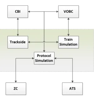
As shown in FigureFigure 1, several sub-systems of the CBTC system, including CBI, VOBC(including ATP and ATO), ZC and ATS shall be linked together through the simulation environment. Each sub-system can have extensions. Simulation sub-system can be replaced by the real sub-system so as to realize easy extensibility, easy substitutability and customizability of the entire simulation environment. The simulation system can be divided into the following three parts in terms of functions.
Trackside Simulation
Trackside Simulation applies computer to simulate real trackside equipment in order to interact with the interlocking. This module adopts the form of reading station chart configuration file to upload equipment list. Then, it sets up a relationship with interlocking input and output digital quantity through logical relationship, responds to the interlocking output and makes feedback to the corresponding interlocking input so as to provide consistent interface for the interlocking and real trackside equipment, ensuring effectiveness of the simulative testing tool.
Train Simulation
Train simulation utilizes computer to simulate real train to interact with the VOBC sub-system. This module adopts configuration file to establish various parameters of the train, such as train length and quality and simulate the running of the train, including speed and displacement as well as simulate the state of the train, including idling and slipping. In addition, it will simulate the train cab controls, including all kinds of buttons, knobs and key switches.
Protocol Simulation
Relevant data network protocols shall be used for each sub-system to conduct network communication interaction. It needs to simulate this part in the simulation system so as to facilitate monitoring over network data and data acquisition.
System Architecture
Figure 2. Simulative Testing Tool System Architecture Diagram.
The architecture diagram of the CBTC simulation system is as shown in Figure 2. The entire system adopts CS architecture and each sub-system is the client side. It is registered to the simulation server through network protocol and the simulation server undertakes various functions as the core part of the entire system, such as data interaction with each sub-system, data storage and distribution, logic calculation and configuration management.
balisescope, this activated data will be sent to the VOBC sub-system so as to achieve a complete train-ground data interaction process. In addition, the trackside equipment simulation conducts digital quantity input and digital quantity output interaction with the interlocking sub-system. These two modules can be controlled by the failure injection module to complete partial test functions.
In train simulation, taking train movement simulation as its core part, it conducts related interaction of digital quantity and analog quantity with VOBC to meet input and output requirements of business subsystem. Moreover, through the bridge interface simulation module, it provides more intuitive and more realistic cab operating environment for testing personnel and relevant training personnel. Through failure injection to the train model simulation module and train control simulation module, the testing personnel can exert corresponding control and change over the current running state of the train in order to achieve desirable test result.
In DCS protocol simulation, simulation mainly conducts data storage, management and distribution between subsystems but doesn’t involve parsing of internal interface of the subsystem.
Simulation System CS Architecture
CBTC simulation system observes CS architecture as a whole, adopts each sub-system as the client side and simulation server as the server side. This architecture has the following advantages: Great extensibility
Each sub-system is independently managed at the server side and will not affect each other. It only needs to start or close corresponding programs at the client side to complete “add or delete” subsystem without the need of configuration management over the server manually. The server side can conduct corresponding management operations automatically according to the type of the registered subsystem. Even if there is a new subsystem, it can have incremental development by observing the previous architecture with great extensibility.
Easy for deployment
Due to natural advantages of CS architecture, the sub-system and server only need unobstructed network to be distributed over multiple sets of pc terminals. In environment like server, it can conduct module distribution according to the actual needs and divide corresponding network based on module distribution so that the entire simulation environment is cleaner and easier to manage. In addition, each sub-system can be independently deployed and not limited to the performance bottleneck of the same set of pc, which can cope with more data and more subsystems.
Data concentration
The server side has all subsystem data and interaction process, making it easier for management, regulation and monitoring across the subsystems.
Hardware and Software Compatibility
Figure 3. Single Machine Version Structure Diagram.
As shown in Figure 3, when the business software is pc version stand-alone software, the top layer CBI is the computer-based interlocking subsystem in the CBTC sub-system and this client middle tier will be compiled into the executable program of the subsystem as the class library of the business subsystem. It will accept the subsystem input, be transferred into a format identifiable by the simulation server to transmit the same to the simulation server side, periodically receive returned data from the server side and send back the data to the subsystem by packaging into the format identifiable by the subsystem. It should be noted that at this time, the interface protocol between the client middle tier and the business subsystem is completely the same as the interaction protocol of the business subsystem with the platform when running on the real cabinet. In this way, it can shield the sub-system from relying on the external environment. The subsystem doesn’t need and shall not adjust corresponding codes according to different external environment. This approach will make the entire simulation environment more convincing and make it easier for code maintenance of the subsystem.
Figure 4. Real Machine Version Structure Diagram.
Software Design and Realization
[image:5.612.228.374.108.275.2]Simulation Configuration Data Organization
Figure 5. Simulation Configuration File Data Management.
As shown in Figure 5, considering extensibility and ease of data management, XML form is adopted for inputting various data. Through XML file parsing, it can generate corresponding simulation objects. It can easily switch between different line data by adopting this way. Also, it can customize corresponding train model parameters according to needs. Moreover, it can reduce relevance between codes and items by adapting to change of input and output code bit table of interlocking and train in different items.
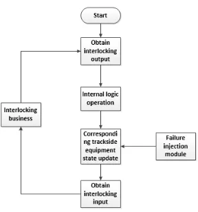
Trackside Equipment Simulation Flow
Figure 6. Trackside Simulation Flow Diagram.
[image:5.612.236.380.411.565.2]LEU Simulation Flow
Figure 7. LEU Simulation Flow Diagram.
As shown in Figure 7, the interlocking sub-system will periodically send data to the LEU simulation module. The LEU simulation module will screen, find out the activated message and transferred to the transponder module. The train simulation kinematics module judges whether the current train position passes through corresponding transponder. If so, it will send the transponder message to the train business sub-system. If not, it will end the current cycle and wait for the next cycle.
Train Simulation Flow
Figure 8. Train Simulation Flow Diagram.
DCS Module Simulation Flow
Figure 9. DCS Module Simulation Flow.
As shown in Figure 9, in this module, DCS module realization is not included in simulation server. The simulation server is responsible for interacting with the business subsystem and calling corresponding functions in DCS module according to the interaction results. DCS module mainly undertakes functions like establishing and disconnecting corresponding links, sending data and receiving data.
Results
Figure 10. Station Chart Display.
As shown in Figure 10, this interface is the simulated station chart UI display. The station data is obtained from xml configuration file and indicated on UI through drawing data and so on. Trackside equipment and so on of the complete line station chart can be viewed form UI. Various corresponding operations such as failure injection to the trackside equipment can be conducted.
As shown in Figure 11, this module is the bridge simulation module, which is responsible for operating the simulated train bridge. Besides the common operations of the bridge on this interface, it also displays relevant information of the train like current speed and acceleration. After the train is running, the corresponding speed information will be also displayed on the train user interface.
Conclusion
This article has generally introduced all functions to have and general module division of the CBTC Simulative Testing Tool starting from the function of the CBTC simulation sub-system. Moreover, it designs the entire system architecture by taking into consideration of extensibility and ease of use. Finally, it gives detailed introduction to the general function flow of the simulation module by combining various subsystem modules, constructs a simulative testing tool environment in the CBTC system through independent research and development, which has greatly improved the research and development efficiency of the entire self-developed system and providing powerful support and guarantee for application of self- developed system in practical engineering.
Acknowledgment
This work is supported by the funding from the National Science and Technology Infrastructure Program of China under Grant 2015BAG19B03.
References
[1]Yin Xunzheng, Li Liang, Research and Realization of CBTC Simulation and Training [J]. Railway Signalling & Communication, 2013, (49):141-143.
[2]Wang Wei, Zhang Jianming, Minimum-system based CBTC Simulation Test Platform[J], Urban Rapid Rail Transit, 2011, 24(4):33-36.