2016 Joint International Conference on Artificial Intelligence and Computer Engineering (AICE 2016) and International Conference on Network and Communication Security (NCS 2016)
ISBN: 978-1-60595-362-5
Trajectory Correcting Algorithm of Active Dancing Robot Based on IMU
Zhao LIU
1,2,a,*, Li-Bin SONG
2,b, Tao YU
2,c, Zeng-Xi WANG
2,d, Kai GUO
2,e,
Mei-Xiao GENG
2,f1Tianjin Research Institute for Advanced Equipment, Tsinghua University, Tianjin, China 2Tsingyan Huayu Robot and Automation (Tianjin) Co., Ltd., Tianjin, China
a[email protected], b[email protected], c[email protected], d[email protected], e[email protected], f[email protected]
*Corresponding author
Keywords: Dancing Robot, Trajectory Correcting, Attitude Angle.
Abstract. This paper presents a trajectory correcting control algorithm of active dancing robot based
on IMU (Inertial Measurement Unit). Kalman filter was used for obtained attitude angles caused by human. Threshold filter was used to eliminating the jitter errors. Relative attitude angles to velocity vector mapping could be got after state judgment. Combined expected velocity with the artificial velocity, actual motion trajectory and correction value of the rest points could be obtained. Test using Waltz step CCL (Closed Change Left) and CCR (Closed Change Right) shows the effectiveness and reliability of this control algorithm.
Introduction
With the rapid development of robot technology since the appearance of traditional industry robot, robot is no longer restricted to industrial applications. Future robot technology is developing to directions covering fields of daily life, such as the catering industry, entertainment industry, companions [1]. At the same time, the requirement of initiative of the robot based on human-machine cooperation have become higher and higher. It means that not only can the robot move under the action of people, but also collaborate with people on the basis of prior knowledge [2].
This paper chose the active dancing robot as the main study object. The active dancing robot can lead people to dance according to the preliminary knowledge, and what’s more, it can change steps according to the external force of human. This would avoid people being injured and implement friendly human-machine cooperation, and make the dancing robot have characteristics of intelligence, autonomy and interaction.
Multi axes force sensors, which is simple, accurate, but expensive, have been used in most traditional control system of human-machine cooperation robot to detect force changes [3]. In this paper, several springs and a six axis IMU mount on waist of the robot are used instead of multi axes force sensors. And the direction and magnitude of force by human and human intention were judged according to changes of relative attitude angle. The robot then corrected its original trajectory to ensure action coordination and human’s safety.
IMU Data Fusion Based on Kalman Filter
The attitude model of dancing robot is descripted in the following expressions, where
α
is the attitude angle of the robot,u
is the measured value of gyroscope, β is steady-state error of gyroscope, and dt is sampling interval.‐1 ‐1‐ ‐1 .
k k k k
α α u β dt (1)
Steady-state error of gyroscope is considered as constant in the state estimation:
‐1
k k
β β
Then we changed the two equations in matrix form:
1 1
1
0 1 0 k .
k k
dt dt
u
(2)
Thus, the calculation process of data fusion based on Kalman filter can be described as follows [5]: (1) Build up systematical state equations:
‐1
‐ 1 k .
X k AX k Bu (3)
1
0 1
dt A
, 0
dt B
, X k is k time prediction result, X k‐ 1 is k ‐ 1 time optimal result.
(2) Predict new error P k according to the last error covariance P k‐ 1 and process noise.
‐ 1 T .
P k AP k A Q (4)
T
A is the transpose of A , Q is the covariance matrix of the system process, and
_ 0
0 _
Q acce
Q
Q gyro
, Q_acceis covariance of accelerometer, Q_gyro is measurement covariance
of gyroscope.
(3) Calculate the Kalman gain, where H is system observation matrix, and H
1 0
.‐1.
T T
g
K k P k H HP k H R (5)
(4) Update the result and get the best estimation X k .
‐ 1 g ‐ ‐ 1 .
X k X k K k V k HX K (6)
(5) Update the k time error covariance P k , where I is the unit matrix.
‐ g ‐ 1 .
P k I K k H P k (7)
So circulates, until the optimal attitude angles of the dancing robot were got.
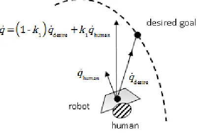
The motion state of the active dancing robot consists of two parts. One is desired velocity based on prior learning steps, the other is the velocity caused by artificial force. It is assumed that the desired velocity is qdesire and the artificial velocity is
human
q . The resultant velocity q x y θ , ,T is shown in Fig.2, and it can be described as:
1‐ 1 desire 1 human .
q k q k q (8)
1
[image:3.612.206.406.203.338.2]k is the weight of influence by artificial velocity, and its value is in the range of 0 to 1.
Figure 1. Composite velocity figure of the robot.
Active Motion Trajectory of the Robot
The track coordinates and time series of the active dancing robot are determined by prior learning steps and the accompanying music. Assuming the robot is moving on a track, and its desired move law can be descripted as follows:
di di
T f
g
, ,
di di
di di di di
y x
θ x
q x y θ
, xi x xi 1. (9)
di
f x and gdi x are functions of trajectory after cubic spine interpolation. di
q is the desired velocity on the desired trajectory.
Force Influences Algorithm on the Robot Movement
The upper body and lower body are connected by springs, and the IMU module is placed horizontally on a disk. The values of IMU module will change when pushing or pulling the robot, and the changes of force will be reflected to attitude angles changes through Kalman filtration method, and then the robot can recognize the direction and magnitude of human. To this the robot can surrender to person and avoid person from injured.
Calculation of Relative Attitude Angles. The attitude angles need to be corrected because of
errors of mechanical structure and installation process.
We would like to take attitude angles of three directions N1 times when the robot is still and without any external forces. Then we could get the roll angle Roll0, the pitch angle Pitch0and the twist angle
Twist0by calculating average values. And then calculating the three attitude angles in real time and
0 0 0 ‐ ‐ ‐ re re re
Roll Roll Roll
Pitch Pitch Pitch
Twist Twist Twist
(10)
But in practice, the spring stiffness must consider both the stability in movement process and the sensitivity responding to external force, and there inevitably existed minor shaking. Considering the above factors, adaptive threshold should be selected to adjust the attitude angle values. The adjusted values are shown in Eq.11,p, q, m are attitude angles jitter errors of three directions respectively.
0, , 0, , 0, , . re re re re re re re re re re re re Roll p Roll
Roll Roll p
Pitch q
Pitch
Pitch Pitch q
Twist m
Twist
Twist Twist m
(11)
Calculation of Relative Attitude Angles. The attitude angles need to be corrected because of
errors of mechanical structure and installation process.
Relative Attitude Angles to Velocity Vector Mapping. The attitude angles of the upper body of
the dancing robot are monotonically increasing with force, but an excessive force may cause damage to springs. At the same time, the spring stiffness is always large to avoid shaking, so normal force could not produce large deformation. Therefore, the force produced by human is convergent to a maximum value, as is shown in Eq.12. θ is the attitude angle caused by human, θmax is the maximum value of the attitude angle.
‐
max 1 ‐
bθ
human
F F e , | |θ θmax. (12)
Kinetic equation of dancing robot under the force of human is shown in Eq.13. Mh is virtual inertia matrix, Dhis virtual damping coefficient matrix, qh is motion velocity, qh is motion acceleration.
.
h h h h
human
F M q D q (13)
Movement Decision Based on State Judgment. The attitude angles and kinetic equation could
not be used directly; current state must be considered for human-machine cooperation calculation, since we do not expect the robot to move under a sudden and short-time force when the robot is under a static condition.
Human-machine Cooperation Control
The control signal was transmitted to the robot at 50HZ. The expressions of robot trajectory can be deduced in Δ
t
time periods according to Eq.8, as is shown follows:
0 0 0 . t i t i t ix x t dt y y t dt θ θ t dt
Thus, the pose expression when the robot is at the ith position can be expressed as Eq.15, and all target points coordinates after the ith point should be corrected because of human force.
1
1
1 .
i
i di j
j i
i di j
j i
i di j
j
x x x
y y y
θ θ θ
(15)
Experiments
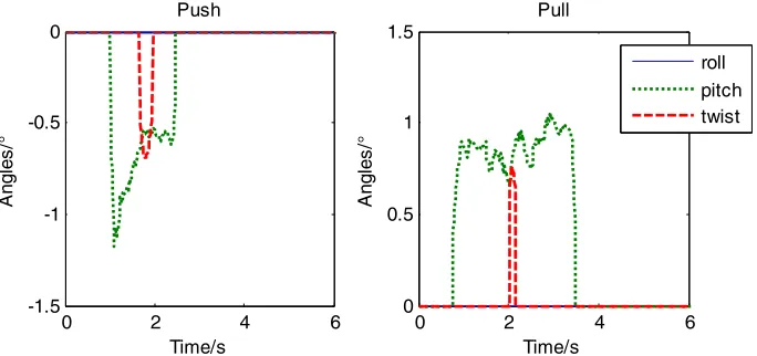
An experiment was presented using a basic step in the waltz called CCL and CCR according to the trajectory correcting control algorithm proposed in the thesis. In the experiment, people push the robot for a while when the robot performing the step CCL and pull the robot for a while when the robot performing the step CCR. After Kalman filtration of acceleration and angular velocity data collected by IMU module, the curves of roll angles, pitch angles and twist angles were shown in Fig.2.
The sensitive variable to reflect the “push” and “pull” action was the pitch angle, but the other two angles had minor change as well. After threshold filtering algorithm, the relation curves of relative attitude angles were shown in Fig.3.
0 2 4 6
-4 -3 -2 -1 0
1 Push
Time/s
A
ngl
es
/°
0 2 4 6
-3 -2 -1 0
1 Pull
Time/s
A
ngl
es
/°
roll
twist
pitch
roll
twist
[image:5.612.152.456.357.513.2]pitch
Figure 2. The curves of attitude angle when pushing the robot.
0 2 4 6
-1.5 -1 -0.5
0 Push
Time/s
A
ngl
es
/°
0 2 4 6
0 0.5 1
1.5 Pull
Time/s
A
ngl
es
/°
roll pitch twist
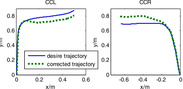
[image:5.612.142.484.548.709.2]While wanted the robot to slow down when people pushing the robot in CCL step and pulling the robot in CCR step, we didn’t want it to rotate at the same time. Then state judgment was needed to eliminate the effect of transient change twist angle. Based on these, we could get comparison curves of desired trajectory and corrected trajectory, as shown in Fig.4.
0 0.2 0.4 0.6
0 0.2 0.4 0.6 0.8
CCL
x/m
y/
m
-0.6 -0.4 -0.2 0 0
0.2 0.4 0.6 0.8
CCR
x/m
y/
m
[image:6.612.159.458.128.274.2]desire trajectory corrected trajectory
Figure 4. Curve comparison of the desired trajectory and man-machine collaboration track.
The experimental results show that the trajectory correcting algorithm is efficient and reliable.
Summary
In this paper, the human-machine cooperation questions of active dancing robot were studied when applying a force on it, and the trajectory correcting algorithm based on IMU module was carried out. After data fusion of acceleration and angular velocity using Kalman filter and a series of logical judgment, relative attitude angle of upper body of the robot could be obtained. And the angles could reflect the direction and magnitude of force by human. Through the trajectory correcting algorithm, the robot could dance with people safely. Experimental results demonstrate the effectiveness of the algorithm.
Acknowledgement
This research was financially supported by the National Science Foundation of China (No.51005126).
References
[1] Min Tan, Shuo Wang, Research progress on robotics, J. Acta Automatica Sinica. 07 (2013) 963-972.
[2] Ting Wang, Yue-Chao, Wang, Human-machine system and its application to mobile robot, J. Robot. 06 (2004) 553-557.
[3] Kosuge K., Hayashi T., Hirata Y., et al. Dance partner robot: MS DanceR [C]//Proceedings of the 2003 IEEE/ RSJ International Conference on Intelligent Robots and Systems. Las Vegas, Nevada, USA: IEEE, 2003: 3459-3464.
[4] Zhi-Yong Feng, Han Zeng, Li-Zhang et al. Angle measurement based on gyroscope and accelerometer signal fusion, J. Journal of Southwest China Normal University (natural science edition). 04 (2011) 137-141.
[5] Shuai Wang, Guo Wei. Application of Kalman filter in attitude measurement for four-rotor aircraft flight, J. Ordnance industry automation. 01 (2011) 73-74+80