2016 International Congress on Computation Algorithms in Engineering (ICCAE 2016) ISBN: 978-1-60595-386-1
1 INTRODUCTION
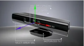
[image:1.516.291.436.332.412.2]Kinect [1, 2] is a new game controller technology in-troduced by Microsoft in November, 2010. Since its launch date, it was evident that Microsoft’s device is transformed not only in computer game but also in many other applications like robotics and virtual real-ity due to its abilreal-ity to track movements and voices and even identify faces, all without the need for any additional devices [3]. Kinect (Figure 1) interprets 3D scenes from a continuously-projected infrared struc-ture. It has a webcam like structure and allows users to control and interact with a virtual world through a natural user interface, using gestures, spoken com-mands or presented objects and images. The device includes a RGB color camera, a depth sensor and a multi-array microphone. It provides the full-body 3D motion capture and the facial and gesture recognition. The depth sensor consists of an infrared laser projector combined with a monochrome CMOS sensor, and allows the Kinect sensor to process 3D scenes in any ambient light condition [2]. The depth sensor technol-ogy was developed by Israeli Prime Sense [4]. It inter-prets 3D scene information from a continuous-ly-projected infrared structured light. A variant of image-based 3D reconstruction was used to recover the depth of the observed points in the 3D scene [5]. Kinect is able to simultaneously recognize up to six people, including two moving players, for motion analysis with a feature extraction of 20 joints per ac-tive player.
Figure 1. The Kinect device by Microsoft.
As a simple and natural way of communication, gesture has become an important means of man-machine interaction [6-9]. A gesture track is to recognize the meaning expressed by a moving arm according to certain rules. The application of gesture track information has good portability and expansibil-ity. However, the segmentation method of the vi-sion-based gesture track recognition is susceptible to the influence of light, background and camera perfor-mance, which may result in low recognition rate. Ki-nect, the motion sensing device designed by Microsoft uses sensors to obtain the position coordinates of hu-man joints and depth data, providing a sound basis for further gesture track recognition. This algorithm per-forms segmentation and recognition on depth images using the coordinate information and tracks obtained by Kinect sensors. This method is not affected by such factors as light and background, which has enhanced the consistency and robustness of gesture track recog-nition.
Track-based Gesture Recognition Method Based on Kinect
Ying Wang*
Computer Information Center, Beijing Institute of Fashion Technology, Beijing, China
ABSTRACT: This paper presents a new gesture track recognition method based on the depth image infor-mation received from the Kinect sensor. First, a Kinect sensor is used to obtain the coordinates of a moving arm. Then, the gesture tracks corresponding to these coordinates are analyzed. Matching and recognition of gesture tracks are implemented by performing golden section search. The results show that this track-based method is highly effective in gesture recognition.
Keywords: gesture track recognition; Kinect
2 POSE AND GESTURE
Movement is dynamic while posture is static. Gesture and pose can be respectively understood as movement and posture. Gesture is made up of a series of contin-uous movement of a body part in the space, such as the act of waving and of swiping. The gesture of swiping will get the response in speed and direction in a Kinect system. To be specific, hands swiping over-head, the rolling direction and speed on the screen will be consistent with that of the hands. Pose is a static relationship of spatial layout of bodies’ different parts. The “universal pause” in the Xbox game which can be achieved by raising hands 45 degrees is the most well-known case.
For simple games, hands and fingers are the body parts which are used most frequently to control scene other than motion sensing games. Hand movement is of the greatest variety, of the easiest identification and of the highest recognition rate in all the body move-ments, thus becoming the first choice of interactive measure. Hand movement is characterized by nature, simplicity and richness. Gesture recognition can be divided into following categories:
- Algorism matching:
Match simple gesture by tracking the spatial rela-tionship between the body parts with the knowledge of geometry and trigonometry,
- Template matching:
Make a comparison between the sequence of ges-ture movement and the proposed movement template, and conduct recognition work by measuring their sim-ilarity
- Neutral network and support vector machine:
Neutral network recognition technique is character-ized by self-organizing ability, self-learning ability, the uniformity of the distribution and the mode gener-alization ability. It can effectively counter noise and solve incomplete mode. Support vector machine is developed based on statistical theory, having better inference ability than neutral network.
- Statistical analysis and machine learning:
It is one of classification methods to train computer vision technology by collecting eigenvectors. It is also a classification method based on probability and Bayesian maximum similarity theory. This technology cannot be used for the direct recognition of original data. Instead, it can be used to extract specific eigen-vectors from a large amount of data.
There are seven universal gestures in Kinect games and applications: wave, hover button, magnet hover button, swiping, slide unlock and universal pause. A train of thoughts on how these gestures’ recognition is realized are summed up.
- Wave:
Wave is usually a method to say hello in the real world. In Kinect games and applications, wave can be the cursor control to activate a screen.
Analyze the gesture of wave, and the motion rule of it can be found out.
Bending arms at the position of elbow, users move forward and backward forearms with elbow as an axis. This gesture is somewhat repetitive and time -continuous.
Wave recognition is judged based on the angle of the line crossing HandLeft (HandRight) and El-bowLeft (ElbowRight) off the plane. Triangular cal-culation is too complicated. Therefore, another meth-od is used. In this methmeth-od, the state is determined by comparing the coordinate along x-axis between HandLeft and ElbowLeft when the coordinate which is along y-axis of HandLeft is larger than that of El-bowLeft.
- Hover button:
Because there is not a mouse click event in GUI world for motion sensing operations, the hover button is used to transform the mouse click into hang and wait. Timer is used to record the objective button event where cursor stops. The click time is triggered when the threshold of the continuous time is reached.
The mechanism for hover control is not complicated. Collide to determine whether it is on a button, and present the hover process with timer and cartoon. The click time is triggered when the threshold of the con-tinuous time is reached.
- Swiping:
In the traditional window interface, a piece of in-formation, if cannot be presented in a screen, is re-vealed with scroll bars. Whether in Metro Style or in UI style of iPad, touch can be used to switch display screens.
In interactive interface, the horizontal slide is a common gesture. But the vertical slide affords a better user experience, thus becoming a better tool to be used in interactive interface. And vertical scrollbars are well applied in the slide and touch interface.
- Slide to unlock:
Hover button is a wonderful interactive design, but it has a disadvantage of requiring users to wait for two seconds. In Xbox games, no one likes waiting. Slide button can be regarded as the combination of hover button and slide gesture.
Slide button is also used for timer. It can lock the current operating target but not trigger any event; the next “slide” gesture will trigger events. It has a more flexible operation. And it can prevent users from waiting, thus providing a more comfortable user expe-rience.
- Push button:
Push button is first designed to copy the button on the traditional GUI interface in Kinect. As a similar action to the mouse click, press button can be simu-lated by a gesture of pushing hands forward.
along the negative direction of the Z-axis. A reference point, such as the coordinates of users’ heads, can be chosen for the calculation of the distance of the movement. When the distance of hand movement exceeds the preset threshold, an event like “mouse click” will be triggered.
- Universal pause:
As is known to Windows users, the ESC key in the keyboard performs a function of universal pause. The gesture of universal pause is one of the guiding ges-tures offered by Microsoft. And this gesture is realized by raising one’s left arms at 45 degrees off his body. The algorism of universal pause is relatively simple. It can be determined based on the angle of one’s left arm off his body and the angle threshold.
3 MOTION DETECTION BASED ON SAMPLES
[image:3.516.268.456.442.640.2]Suppose that movements can be recorded and serial-ized. If the ongoing movement is one of those that happened before, it can be detected. The main purpose is to quickly determine whether the data of the ongo-ing movement matches that of any previous movement [10, 11]
. All movements are in the form of sets of coor-dinates. However, the coordinates only represent the distance from the sensor. Therefore, there is a need to propose an algorithm for data comparison. In addition, the data should be standardized and converted so that they are in the same reference space.
Suppose that the coordinate series is shown as fol-lows:
P = {𝑝0, 𝑝1, … , 𝑝𝑛−1}
- Generate the movement with a specific number of coordinate points
Suppose that the number of samples is 𝑀. The dis-tance between two samples is defined as 𝐿𝑎𝑣𝑔= (𝑛 −
1)/(𝑀 − 1). The distance between 𝑝𝑖−1 and 𝑝𝑖 is defined as 𝐿𝑖,𝑖−1. In the sampling process of coordi-nate series according to the number of samples, the new coordinates of sampled points need to be recalcu-lated. The recalculation is implemented by traversing points corresponding to coordinate series. If the dis-tance between the current point and the last sampling point cannot reach the sampling point, the traversal continues. If the distance reaches or exceeds the sam-pling point, the coordinate point needs to be recalcu-lated. So a variable 𝐿𝑐𝑢𝑟 representing the accumula-tive distance during the traversal needs to be defined. When 𝐿𝑐𝑢𝑟+𝐿𝑖,𝑖−1>=𝐿𝑎𝑣𝑔, the new coordinate point is shown as follows:
𝑝′𝑖= 𝑝𝑖−1+ (𝐿𝑎𝑣𝑔− 𝐿𝑐𝑢𝑟/𝐿𝑖,𝑖−1) ∗ (𝑝𝑖− 𝑝𝑖−1) (1)
The new coordinate series is shown as follows:
P′ = {𝑝′0, 𝑝′1, … , 𝑝′𝑛−1}
- Rotate the coordinate point so that the first point is at 0 degree
In order that the two matched series have the same starting point, the coordinate series are rotated until the first coordinate point is at 0 degree. Then the cen-ter coordinates of the coordinate series are calculated. The direction angle of the first coordinate point rela-tive to center coordinates is obtained. A new coordi-nate series is generated by setting this angle as the direction angle and using the rotation matrix in the two-dimensional space.
- Map the coordinates to the specified coordinate level [0, 1]
As the value range of the coordinate series has not been unified, inaccuracy may arise. So, the coordi-nates need to be set within the interval [0, 1].
- Standardize the origin of the series of movement points
After this standardization, the matching will be performed. The coordinate series with the same length are resized in the unified scale, direction and centers.
Start the gesture:
(a)
Generate a new gesture with a defined number of points:
(b)
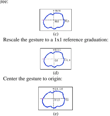
Rotate the gesture so that the first point is at 0 de-gree:
(c)
Rescale the gesture to a 1x1 reference graduation:
(d) Center the gesture to origin:
(e)
Golden section search [15] is a technique for finding the extrema by successively narrowing the range of values of a monotone continuous function inside which the extremum is known to exist. The technique derives its name from the fact that the algorithm maintains the function values for triples of points whose distances form a golden ratio. Golden section search is more real-time and convenient than deriva-tives in finding the extremum of a function.
Consider the function in the interval [a, b]. Suppose that 𝑓(𝑥) is a continuous unimodal function in [a, b], then 𝑓(𝑥) has only one minimum or maximum in [a, b]. The best way to find this extremum is to use the bisection method. Similar to the bisection method, GSS algorithm narrows down the interval in which the extremum exists by comparing function values. Two objectives must be fulfilled in designing the algorithm. First, the optimal interval narrowing factor can be found in the interval. Second, the number of function calls must be reduced.
Enlightened by the bisection method, one choice is to calculate the intermediate point m = (a + b)/2 . Then find the values of 𝑥1and 𝑥2and, define
𝑥1= 𝑚 − 𝛿/2 and 𝑥2= 𝑚 + 𝛿/2. δ is a small pa-rameter that makes 𝑓(𝑥1) ≠ 𝑓(𝑥2). If (𝑥1) < 𝑓(𝑥2), we reserve [a, 𝑥1], otherwise we set [𝑥2, b] as the new region of search. However, two calculations need to be performed to solve the function in each narrowing operation. This is not the optimal method.
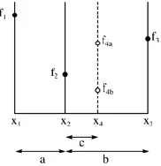
Figure 3 shows one step for finding the minimum. The function value of 𝑓(𝑥) is on the vertical coordi-nate axis. The parameter x is on the horizontal coor-dinate axis. The values of three points on the function
𝑓(𝑥) have been obtained. They are 𝑥1, 𝑥2 and 𝑥3 . It’s thus clear that 𝑓(𝑥2) is smaller than 𝑓(𝑥1) and
𝑓(𝑥3). Obviously, the minimum exists between 𝑥1 and 𝑥3.
The next step is to calculate the value of the func-tion at another point 𝑥4. It is more efficient to chose
𝑥4 in the largest interval, for example, between 𝑥2 and 𝑥3. It can be seen from the figure that if the func-tion value exists in 𝑓4𝑎, the minimum will exist be-tween 𝑥1and 𝑥4, and a new group of points will be
[image:4.516.108.199.554.648.2]𝑥1, 𝑥2 and 𝑥4. If the function value is 𝑓4𝑏, the new group of points will be 𝑥2, 𝑥4 and 𝑥3. So, in both cases, we can build a new narrower search interval that contains the function’s minimum.
Figure 3. Standardization of the gesture track.
Consider a function 𝑓 over the interval [a, b]. We assume that 𝑓(𝑥) is continuous over [a, b]; and that
𝑓(𝑥) is unimodal over [a, b], i.e. 𝑓(𝑥) has only one minimum in [a, b]. Note that the method applies as well to find the maximum [13, 14, 15].
The conditions above remind us to the bisection method and we will apply a similar idea: Narrow the interval that contains the minimum comparing func-tion values. In designing the method, we seek to satis-fy two goals. We want an optimal reduction factor for the search interval and minimal number of function calls. With these goals in mind, we are going to de-termine the location to evaluate the function.
One choice inspired by the bisection method would be to compute the midpoint m = (a + b) = 2 and to evaluate at 𝑥1 and 𝑥2, defined by 𝑥1= 𝑚 − 𝛿/2 and 𝑥2= 𝑚 + 𝛿/2, for some small value 𝛿 for which 𝑓(𝑥1) ≠ 𝑓(𝑥2). If 𝑓(𝑥1) < 𝑓(𝑥2), then we are left with [a, 𝑥1], otherwise [𝑥2, b] is our new search interval. While this halves the search interval in each step, we must take two new function evaluation in each step. Therefore, this is not optimal.
We only need to perform a new function evaluation in each step. Furthermore, we need a constant reduc-tion factor, say, 𝑐, for the size of the interval.
In order to increase the efficiency of the algorithm, the function solving process operation should be per-formed only once in each step. Be relative to the cur-rent search interval, a constant factor c is defined. And there are two cases for 𝑥1 and 𝑥2 in [a, b].
If (𝑥1) < 𝑓(𝑥2), we make [a, b] := [a, 𝑥2] and make the following adjustment in the interval:
(2)
If (𝑥1) > 𝑓(𝑥2), we make [a, b] := [𝑥1,b] and make the following adjustment in the interval:
(3)
So long as C is known, position 𝑥1 and 𝑥2 can be obtained. Without loss of generality, we consider the case (𝑥1) < 𝑓(𝑥2). To simplify the calculation, we suppose that [a, b] = [0, 1].
If (𝑥1) < 𝑓(𝑥2), we set 𝑥1= 1 − 𝑐 repeatedly and determine whether the next value should be se-lected from the left or right of 1 − 𝑐.
Suppose that a function value is obtained from the left of 𝑥1= 1 − c, then 𝑥1 is the right boundary of [0, c]. The expression of 𝑥1 can be written in two forms. (𝑎 = 0 and 𝑏 = 𝑐 in the expression where 𝑥2 is used)
1 − c = (1 − c)0 + cc ⇒ 𝑐2+ 𝑐 − 1 = 0 (4)
The positive root c = (−1 + √5)/2 is approxi-mately equal to 0.6180.
[0, c]. The expression of 𝑥1 can be written in two forms. (a = 0 and b = c in the expression where 𝑥1 is used):
1 − c = c0 + (1 − c)c ⇒ (1 − 𝑐)2= 0 (5)
The root of equation (5) is 1. The interval is not narrowed down. This possibility is thus ruled out. Two rules are obtained: If 𝑓(𝑥1) < 𝑓(𝑥2), we reserve 𝑥1, make 𝑥2 and calculate a new value for 𝑥1 through using equation (3). If (𝑥1) > 𝑓(𝑥2), we reserve 𝑥2, retain it as 𝑥1 and calculate a new value for 𝑥2 through using equation (2).
4 RESULTS
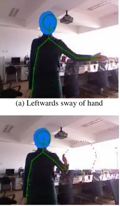
Two experiments are conducted using this algorithm to recognize two kinds of gestures, namely, left-right sway of hand and circular gesture. The gesture tracks are collected from five people. Each person repeats each gesture for ten times. As shown in Figure 4, the hand moving leftwards in the left picture represents a leftward sway and the red dots represent the moving track of the hand. The set of points is used as the sam-ple for recognition. The left picture shows a circular gesture. It can be seen that the sample highly matches the gesture.
(a) Leftwards sway of hand
[image:5.516.93.214.350.558.2](b) Circular gesture recognition
[image:5.516.56.249.609.660.2]Figure 4. Recognition performance
Table 1. Data analysis of the recognition of two gestures.
Gesture Leftwards
sway
Rightwards sway
Circular gesture Times of gesture 50 50 50 Times of recognition 50 49 46
Recognition rate 100% 98% 92%
Table 1 gives out the recognition rate of the two gestures by the five participants. The results show that this algorithm has a high recognition rate which is able to meet demands of practical use.
5 CONCLUSION
In recent years, gesture has increasingly become an important way of man-machine interaction for its ease of use. Based on certain rules, the meaning carried by a gesture track can be recognized. Therefore, the ap-plication of gesture track information is highly porta-ble and expansiporta-ble. The traditional gesture track recognition which is vision-based contains a variety of algorithms. This paper uses the Kinect sensors to ob-tain depth data and perform segmentation and recog-nition over depth images. As this method is free from the influence of light and background, it has increased the consistency and robustness of gesture track recog-nition.
ACKNOWLEDGEMENT
This paper is sponsored by the Youth Innovation Pro-gram of Beijing Institute of Fashion Technology (GN: QTXM02140201/054) and the Beijing Education Commission Scientific Research Support Program (KYJH02150201)
REFERENCES
[1] Frati, V., & D. Prattichizzo. 2011. Using Kinect for hand tracking and rendering in wearable haptics. World Hap-tics Conference (WHC), IEEE, 2011:317-321.
[2] Wikipedia. 2011. Kinect — Wikipedia, the free ency-clopedia. http://en.wikipedia.org/wiki/Kinect, [Online; accessed 13-January-2011].
[3] J. Giles. 2010. Inside the race to hack the Kinect. The
New Scientist, 208(2789):22–23.
[4] Prime Sense. Prime sense kinect’s hardware. http://www.primesense.com, 2010. [Online; accessed 8-January-2011].
[5] How kinect depth sensor works. Stereo triangulation? http://mirror2image.wordpress.com/2010/11/30/how-kin ect-works-stereo-triangulation, Nov 2010.
[6] Kao M C, & Li T H S. 2010. Design and Implementation of Interaction System between Humanoid Robot and Human Hand Gesture. Proc of SICE Annual Conference. IEEE Press: 1616-1621.
[7] Li Qingshui, Fang Zhigang, & Shen Mowei et al. 2002. Application of Gesture Recognition in Man-machine In-teraction [J]. Ergonomics, 8(1): 27-29.
[9] Huang Kangquan, Chen Bijin, & Zheng Bo et al. 2011. Application of Kinect in the Video Conference System.
Journal of Guangxi University: Natural Sciences,
36(z1): 308-313.
[10] Chen Qing, Georganas N D, & Petriu E M. 2007. Re-al-time Vision Based Hand Gesture Recognition Using Haar-like Features. Proc of IEEE Instrumentation and Measurement Technology Conference. IEEE Press, 1-6. [11] Silanon K, & Suvonvorn N. 2011. Hand Motion
Analy-sis for Thai Alphabet Recognition Using HMM. Interna-tional Journal of Information and Electronics Engineer-ing, 1 (1): 65-71.
[12] Ikemura S, & Fujiyoshi H. 2011. Real-time Human De-tection Using Relational Depth Similarity Features. Proc of the 10th Asian Conference on Computer Vision: 25-38.
[13] Ward Cheney & David Kincaid. 1994. Numerical
Mathematics and Computing. Third Edition,
Brooks/Cole Publishing Company.
[14] Curtis F. 2004. Gerald and Patrick O. Wheatley. Applied
Numerical Analysis. Seventh Edition, Addison Wesley.