2017 3rd International Conference on Artificial Intelligence and Industrial Engineering (AIIE 2017) ISBN: 978-1-60595-520-9
A Calibration Method of Cylindrical Sensor of Radial Force
Based on Axial Flow Fan
Hang LIU, Xin-sheng CHE
*and Yun SUN
School of Information Science and Engineering, Shenyang University of Technology, Shenyang 110870, P.R. China
*Corresponding author
Keywords: Radial force, Cylindrical sensor, Multiple angle, Sensitivity, Excitation.
Abstract. A device of calibration using eccentric axial flow fan was designed to calibrate the sensor of radial force. In this paper, centrifugal force generated by eccentricity of rotor of axial flow fan is used to simulate the excitation of the sensor. The internal system of detection and recording is used for data recovery and processing to obtain response and characteristics. After the test of cylindrical sensor with a range of 0-200N, the radial force is linearly related to the output value of ADC. By using the least square method, the outgoing degree is 2.25%, and the sensitivity is 53.3LSB/N. The method verifies the accuracy of the method, and the sensitivity of the maximum deviation is not greater than 1.0LSB/N using the standard force loading at 0°, 60°, 120°, 180°, 240° and 300°. This method provides an effective means for the analysis, design, improvement and manufacture of cylindrical sensors of radial force.
Introduction
A cylindrical sensor of radial force is a kind of sensor to measure the radial force of the pump shaft. It is mainly used in the design and manufacture of equipment of large water pump. The radial force of the pump shaft is that the force in the radius direction of the pump shaft in the process of the pump impeller rotating. The main factors affecting the performance of the pump shaft include the radial force, axial force and mechanical vibration of rotor [1]. If the radial force of the pump shaft is too large, it would lead to the fracture of shaft, a great deal of economic loss and even endanger worker's life [2].
A calibration method of radial force put forward by using the rotation of axial flow fan, and build a platform of calibration system of sensor. The deformation of the elastic element is detected by the internal measuring circuit, and the output data of the sensor is obtained. The input and output characteristic curve of the sensor are determined by the least square method [3]. This calibration method simulates the experimental environment of the cylindrical sensor, which is beneficial to the analysis and design of sensors and pumps.
Method of Calibration
Constitution of Calibration Device
Generation of Radial Force
The weight is fixed at the end of the fan blade of the axial flow fan. As it rotates, the radial force F
generated by the weight is:
ma
F (1)
The means of m is weight, a is the acceleration in the normal direction of rotation. Assuming that
the weight rotates from the position of M0to M1, and takes times Δt. The weight rotates in a certain
radian φ with radius r, as shown in Figure 1. The algebraic value of the rotational speed v of
weights is: r t r t M M v t d d
lim 0 1
0 (2)
Where ω is the angular velocity of the rotating weight (rad/s). When the weight is rotated from
M0 to M1, the velocity variation is Δv. When the φ is very small, the direction of Δv is
approximately perpendicular to the tangential velocity, that is the direction of an in Figure 1, and the
size of Δv approximate the size of arc length. Thus the acceleration can be deduced.
r v t t v t v a t t n 2 0 0
lim
lim
(3)
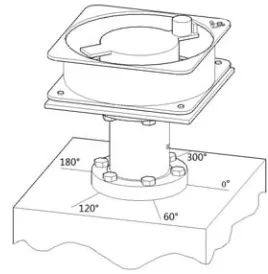
In Figure 2 the direction of 0° and 180° is positive and negative peak direction of sensor.
According to formula 3 can draw that the component force Fa in 0° direction.
) cos(
cos 2
2r m r t
m
Fa (4)
The relation between strain ε and radial force of cylindrical sensor can be deduced from reference
[4]. max 2 max ) cos( y EI t r ml y EI l F n n
a
(5)
Where ymax is the maximum distance between the position of measured deformation and the
neutral layer of elastic element, l is the horizontal distance between weights and strain gauges, E is
called as the elastic modulus of cylindrical elastic element, and the In is called as the moment of
inertia of cylindrical sensor cross section. Full bridge circuit is adopted by this system. The output
voltage is Uo.
k U R R U
Uo i i
Δ
(6)
Where Ui is the voltage of bridge power, R is the resistance value of strain gauges, ΔR is the
variation of resistance value and k is the sensitivity coefficient of strain gauge.
[image:2.612.319.453.586.723.2]Figure 1. Diagram of weight rotation. Figure 2. The calibration system.
φ v1 v0 M1 an v0 M0
System Composition
The calibration system of cylindrical sensor of radial force is composed of eccentric axial flow fan, sensor unit, speed measuring unit and data recovery unit. The sensor unit is used in data acquisition and storage. Speed measurement of axial flow fan is completed by the hall sensor and oscilloscope. The data recovery unit is that reading out of data stored in the flash module through the serial port, and it is conveyed to the computer analysis. The calibration system of cylindrical sensor of radial force is shown in Figure 2.
Eccentric Axial Flow Fan
The main part of eccentric axial flow fan is composed of axial flow fan, and the end of fan blade installed with weight. Using the centrifugal force generated by the weight rotation to simulate the radial force of the pump shaft for calibration.
Sensor Measurement Unit
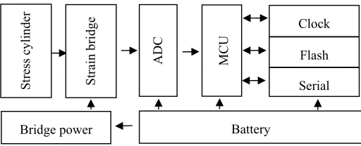
[image:3.612.179.435.305.409.2]The sensor unit of the measurement system is composed of stress cylinder, strain bridge, ADC, MCU, flash memory, serial communication interface, clock interface, bridge power and battery. The structure diagram of sensor unit is shown in Figure 3.
Figure 3. The diagram of sensor measurement unit structure.
Speed Measurement Unit
The speed measuring unit is composed of permanent magnet, the fixed bracket, the hall sensor and oscilloscope. The permanent magnet is fixed near the weight, and above the axial flow fan. Hall sensor is fixed on the axial flow fan by bracket. The 5V power supply is connected to the hall sensor, and the signal is connected with the oscilloscope through the resistance to detect the rotational speed of the axial flow fan.
Data Recovery Unit
The data recovery unit includes a serial port module and the computer software for data processing. Serial module is connected to serial port of MCU. The data in flash memory read out through the serial port module, and put it into computer. Chebyshev band-pass filter is used to eliminate the mechanical vibration and power frequency interference.
Practical Test
Test for Eccentric Axial Fan
According to the above calibration method, the ADC output data is obtained. Take weight of 15.68g an example, the zero drift is removed by data processing software in data recovery device, and initial data is shown in Figure 4. Fourier transform of the data is used to obtain its frequency spectrum, as shown in Figure 5. It can be seen that the data contains DC component, AC component of 45.64Hz and multiple harmonic components of 45.64Hz. Compared with the speed measurement unit, 45.64Hz is the rotation frequency of the axial flow fan when using this weight, which is the
Serial Flash Clock
Battery Bridge power
St
re
ss cyl
inder
Strain
bridge
ADC MC
data value for the experiment [5]. The data are obtained after filtering through the recovery unit, the peak value of the signal is 4832LSB.
0 10 20 30 40 50 60 70 -8000
-6000 -4000 -2000 0 2000 4000 6000 8000
Time/ms
A
D
C
outpu
t/LS
B
0 100 200 300 400 500 600
0 1000 2000 3000 4000 5000
Frequency/Hz
A
m
pl
itude/
LS
[image:4.612.163.492.100.234.2]B
Figure 4. Initial data. Figure 5. Frequency spectrum.
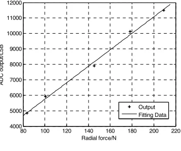
Replace the weight, and make several experiments. The output value of the sensor can be obtained under the corresponding radial force, as shown in table 1. The radial force in table 1 is calculated according to formula 4. Relationship between ADC output value and radial force of sensor is as shown in Figure 6. The result of least square method fitting: the linearity was 2.25%, and the sensitivity was 53.3LSB/N.
80 100 120 140 160 180 200 220 4000
5000 6000 7000 8000 9000 10000 11000 12000
Radial force/N
A
DC o
ut
pu
t/L
S
B
[image:4.612.212.390.319.467.2]Output Fitting Data
Figure 6. Characteristic curve.
Table 1. Experimental results of eccentric axial flow fan.
Weight
/g Frequency /Hz Radial force /N ADC output /LSB 15.68 45.64 83.81 4832 20.26 43.98 100.56 5916 28.95 43.91 145.2 7896 39.65 41.84 178.11 10140 61.38 36.44 209.15 11502
Multiple Angle Radial Loading Test
In order to verify the correctness of the above experimental results, the ADC output of the cylindrical sensor of radial force is measured by the sensor unit when the tension is applied at 0°, 60°, 120°, 180°, 240° and 300°.
[image:4.612.191.423.498.601.2]Table 2. Testing results from multiple perspectives.
Angles /°
Radial force /N Sensitivity /LSB/N
0 40 80 120 160 200 240 280
0 87991 90091 92191 94291 96391 98491 100591 102691 52.5 60 89414 90502 91590 92678 93766 94854 95942 97030 27.2 120 88819 87791 86763 85735 84707 83679 82651 81623 -25.7 180 89777 88745 87713 86681 85649 84617 83585 82553 -52.3 240 89767 88735 87703 86671 85639 84607 83575 82543 -25.8 300 88619 89703 90787 91871 92955 94039 95123 96207 27.1
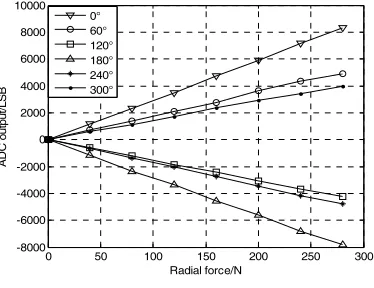
The multiple angle values of different radial forces are obtained after the zero error is removed,
as shown in Figure 7.The sensitivity K1of the multiple angle cylindrical sensor is calculated by the
least square method. Sampling of multiple sine signals obtained by above experiments of eccentric
axial flow fan, the ADC output value of the corresponding angle is extracted. The sensitivity K2of
cylindrical sensor of radial force is calculated by the least square method at each angle. Comparing
K1 with K2, as shown in Table 3.
0 50 100 150 200 250 300 -8000
-6000 -4000 -2000 0 2000 4000 6000 8000 10000
Radial force/N
AD
C o
utp
ut
/L
S
B
[image:5.612.207.394.305.449.2]0° 60° 120° 180° 240° 300°
Figure 7. Multiple angle radial force. Table 3. Comparison of sensitivity in different angles.
Parameters Angles /°
0 60 120 180 240 300 K1 52.5 27.2 -25.7 -52.3 -25.8 27.1
K2 53.3 26.7 -26.7 -53.3 -26.7 26.7
Error
/LSB/N 0.8 0.5 1.0 1.0 0.9 0.4
The error in Table 3 is equal to |K1 - K2|. The sensitivity of the sensor is calibrated by the radial
force generated by the axial flow fan, and the maximum error is 1.0LSB/N with the multiple angle radial force loading test.
The Experimental Results
In this paper, the centrifugal force excited by rotor eccentricity of axial flow fan is used to simulate the interference of the actual radial force of the pump shaft for the output characteristics of the sensor, which is beneficial to the analysis and design of sensors and water pumps. Through the experiment, the relationship between the cylindrical sensor of radial force with a range of 0-200N and the output value of ADC is linear, the linearity is 2.25%, and the sensitivity is 53.3LSB/N. The test of radial loading with different angles corresponds to six angles: 0°, 60°, 120°, 180°, 240°and
300°. The maximum deviation of the sensitivity is less than 1.0LSB/N comparing radial force with
[image:5.612.166.449.482.555.2]References
[1]Y.F. Gao, Research on Axial Force and Radial Force Detection Technology of Pump Shaft,
Master Thesis. Shenyang University of Technology, Shenyang, 2009.
[2]D.F. Zhang, C. Ge, X.L. Li, and et al, Research on calibration method of linearity of high
precision displacement sensor, Journal of Instrumentation, 5 (2015) 982-988.
[3]C.L. Li, Q.C. Chen, Q.S. Ding, Calibration of earth pressure sensor for monitoring soil
compaction, Experimental Technology and Management, 4 (2010) 63-66.
[4]X.F. Sun, Mechanics of Materials, Higher Education Press, Beijing, 2002.
[5]W.C. Bai, Research on Dynamic Calibration System of Multidimensional Force Sensor, Master