http://www.scirp.org/journal/ojfd ISSN Online: 2165-3860
ISSN Print: 2165-3852
A Study on the Half-Ducted Axial Flow
Fan Designed by a Diagonal Flow
Fan Design Method
Atsushi Kaji
1, Yoichi Kinoue
1, Norimasa Shiomi
1, Toshiaki Setoguchi
21Department of Mechanical Engineering, Saga University, Saga, Japan 2Institute of Ocean Energy, Saga University, Saga, Japan
Abstract
A study on the half-ducted axial flow fan designed by a diagonal flow fan sign method was conducted. The rotor which has NACA65 blades was de-signed, calculated numerically, manufactured and tested experimentally. As a result of the design and CFD, the meridional streamline and three distribu-tions of the meridional, tangential and radial velocity at inlet and outlet go well as designed values of the half ducted fan. On the other hand, the values of the meridional velocity and the tangential velocity are little smaller than the design values at the hub side of the radial distribution. The improvement of the design is prospected for this point, that is, the approach between the de-sign value and the actual flow is prospected if the tangential velocity is as-signed small at hub and is asas-signed large at the tip so as to accord the actual flow in the vortex design of the rotor blade. Then the designed half-ducted rotor with four NACA65 blades was fabricated by a three-dimensional printer and tested in the wind tunnel in order to validate the half-ducted design me-thod. For the comparison between the design values and the experimental values at the design flow rate coefficient of φ= 0.264, the experimental values of the pressure rise coefficient ψ and the efficiency η are rather small than the design values, while the experimental value of the torque coefficient τ is al-most the same as the design value. However, the experimental value of ap-proximately 0.45 of the maximum efficiency is comparably large value consi-dering for the limitation of the situation of half-ducted. For the comparison between the experimental values and the CFD values at φ= 0.264, the CFD values are almost the same values as the experimental values for all the values of ψ, τ and η. In addition, the tendencies of the CFD values when the flow rate coefficient changes are almost similar as the experimental tendencies, though the flow rate coefficient for the CFD values when ψ or η takes the peak value shifts toward larger flow rate. For the case at rotor outlet at φ = 0.264, two How to cite this paper: Kaji, A., Kinoue,
Y., Shiomi, N. and Setoguchi, T. (2017) A Study on the Half-Ducted Axial Flow Fan Designed by a Diagonal Flow Fan Design Method. Open Journal of Fluid Dynamics, 7, 15-25.
https://doi.org/10.4236/ojfd.2017.71002
Received: December 20, 2016 Accepted: January 13, 2017 Published: January 16, 2017
Copyright © 2017 by authors and Scientific Research Publishing Inc. This work is licensed under the Creative Commons Attribution International License (CC BY 4.0).
values of the meridional velocity and the tangential velocity are larger than the design values at the tip side of the radial distribution.
Keywords
Axial Flow Fan, Half-Ducted Fan, Internal Flow, Streamline Inclination, Numerical Analysis
1. Introduction
A lot of axial fans, which are small size and high efficiency, are used in our daily life, such as a power unit cooling fan of personal computer, a room ventilation fan, and a radiator fan in car engine room. In most applications of fans non- ducted types are used for the space limitation or cost saving. In comparison with the conventional full-ducted fan mainly used in industrial applications, they are called as half-ducted type, semi-opened type and opened type, respectively. Among these types, a half-ducted axial flow fan is focused in this paper. The corresponding design methods for half-ducted types of propeller fans are not studied by many researchers. Recently, many of fans are designed by the inverse design method [1][2][3]. A half-ducted axial flow fan is usually designed pro-vided that both the inflow and the outflow are full-ducted as if it were in the straight pipe. However, in our previous result [4][5], a half-ducted axial flow fan has much more complicated and three-dimensional internal flow than a full- ducted fan. All conventional design methods are not taking the radial velocity component into account. In this paper, the radial inclinations of meridional streamline were considered for the improvement of the design method by using the diagonal flow fan design method. The half-ducted axial flow fans are de-signed by the controlled vortex design by specifying the constant tangential ve-locity both at inlet and outlet of the rotor. Conventional half-ducted fan is usually designed to prescribe almost uniform inflow and outflow as if it was in the straight pipe. However, many axial flow fans are not used in the straight pipe, such as the application of using in the ventilation and cooling systems without pipe. Thus it is important to take the real flow situation into account in design. Therefore, half-ducted axial flow fan was designed to compare with the traditional design of ducted ones by specifying the flow angles according to the previous experimental results of authors [4][5].
2. Design Method
axial flow velocity change and the inclination of the flow surface [7]. In calcula-tion of meridional flow, the radial balance equacalcula-tion was evaluated. Pressure gra-dient from hub to casing occurs to be balanced against centrifugal force by swirled blades. The radial direction distribution of state quantity such as flow velocity is dependent on such the balancing condition, which is called radial equilibrium condition. The following radial balance equation was evaluated at the quasi-orthogonal direction q on meridional plane.
( )
( )
2 2 d d m m CA q C B q
q + ⋅ = (1)
When the compressibility of the fluid is ignored,
( )
1 sin sin d2 tan
cos d
m
A q
r r q
φ ε φ ε
ε
⋅
= ⋅ ⋅ + + ⋅
(2)
( )
1 d d( )2
d d
t
P C rC
B q
q r q
θ θ
ρ
= ⋅ −
(3)
where, Cm: meridional velocity [m/s], Cθ: tangential velocity [m/s], Pt: total pressure [Pa],
ρ
: fluid density [kg/m3], r: radius [m],m
r : curvature radius of
meridional line [m], ε: angle between meridional normal line and
[ ](
deg)
q
ε ϕ λ
= − ,λ
: angle between radial direction and[ ]
deg cos dd r q q λ =
and
ϕ
: inclination angle of revolving stream surface [deg]. The solution of Equation (1) is given as( )
{
}
( )
{
( )
}
2
exp d exp d d
m
C = −
∫
A q q ∫
B q ⋅∫
A q q q C+ (4)where, C is an integral constant, which satisfies the following equation.
2 cos d
c h q m B q G
r C q
K =
π ρ
∫
⋅ ⋅ ⋅ε
(5)where, G: designed flow rate [kg/s], KB: end-wall blockage coefficient. KB was
presumed to be 0.96. The total pressure rise is presumed to be able to calculate by the Euler equation as following.
(
)
2 2
t
P ≅ ∆ = ⋅ ⋅P
ρ η
U ⋅Cθ ∆ = ⋅ ⋅Pρ η ω
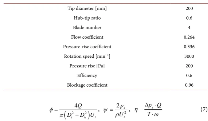
r ⋅Cθ (6)The controlled vortex design method has been applied for half-ducted and ducted propeller fan design by specifying the constant tangential velocity at both inlet and outlet of the fan rotor. Therefore, the meridional velocity and the tan-gential velocity can be obtained so that the calculation of meridional flow is fi-nished. Table 1 shows the designed parameters of ducted fan and half-ducted fan. All these parameters are specified the same value for both of the designed fans.
Table 1. Design parameter.
Tip diameter [mm] 200
Hub-tip ratio 0.6
Blade number 4
Flow coefficient 0.264
Pressure-rise coefficient 0.336 Rotation speed [min−1] 3000
Pressure rise [Pa] 200
Efficiency 0.6
Blockage coefficient 0.96
(
2 2)
4
t h t
Q
D D U
φ π
=
− , 2
2 s
t
p
U ψ
ρ
= , p Qs
T
η
ω
∆ ⋅ =
⋅ (7)
where Ut is speed on the rotor tip. Dt and Dh are the diameter of the rotor tip and hub respectively. Q is the volume flow rate, ∆ps is the static pressure rise, ρ is atmospheric density, T is the rotor torque and ω is the rotating speed of the rotor.
The blade profile on the revolutional plane was selected by referring to the diagram of NACA65 carpet. In order to use the cascade data, the through flow in cylindrical or cone surface must be considered on an averaged stream surface. The flow on revolving stream surface is projected to a plane. Thus, the NACA65 blade with quadrilateral blade on the meridional plane was adopted. Three- dimensional effect of inclination and thickness variation of stream surface on flow field is substituted by the distributions of vortex and divergence on the po-tential theory [8].
3. Design Result
The streamlines on the meridional plane of half-ducted fan were shown in Fig-ure 1. The eleven streamlines from hub to tip were designed so that flow rates between each streamline became equal. In this case, the inclinations of inflow and outflow are given based on the experimental data [4] [5] so as to consider the effect of radial velocity component on the internal flow field. The flow angles of the streamlines are given 63, 16, 38 degrees respectively on tip streamline at inlet, on tip streamline at outlet, on hub streamline at outlet. The blade shapes on top view were obtained showing in Figure 2.
4. Numerical Method and Result
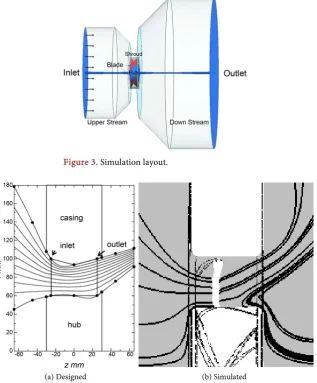
The analysis of the three-dimensional internal flow fields of half ducted fan are conducted comparing to the numeral computation results in the commercial software (Ansys CFX Release 16.0). Simulation conditions and layouts are shown in Table 2 and Figure 3.
Figure 1. Design result of meridional streamline.
Figure 2. Design result of NACA65 blade shape.
Table 2. Simulation conditions.
Software: Ansys CFX Release 16.0 RANS (Reynolds Averaged Navier-Stokes Simulation)
Air Temperature: 25˚C (Density: 1.185 kg/m3)
Turbulence model: SST k-ω model Relative Coordinate System (Shaft Speed: 3000 min−1)
Mass Flow Inlet (0.1971 kg/s, Uniform) Pressure Static Outlet (1 atm, Uniform)
Wall Boundary: Dirichlet boundary, No Slip (Counter Rotating Wall in Shroud)
Axial location z mm
R
a
d
ia
l
lo
ca
ti
o
n
r
m
m
Hub Casing
Leading edge Trailing edge
Flow
-60 -40 -20 0 20 40 60
the perspective view of the calculated region for the full-pitch calculation. The unstructured, tetrahedral grids were used. The total number of the grids is ap-proximately 5,550,000. The tip clearance of 2 mm is set for the numerical calcu-lation.
The turbulence model was SST. The use of a k-ω formulation in the inner parts of the boundary layer makes the model directly usable all the way down to the wall through the viscous sub-layer. The SST formulation also switches to a
k-ε behaviour in the free-stream and thereby avoids the common k-ω problem that the model is too sensitive to the inlet free-stream turbulence properties. Es-pecially, the influence of stall by separated flow at low flow rate can be better si-mulated in SST turbulence model. Therefore SST turbulence model was adopted.
[image:6.595.218.536.334.718.2]Figure 4 shows the designed and simulated streamlines. The designed and simulated streamlines are similar tendency. Figures 5-7 present the distributions of circumferentially averaged meridional, tangential and radial velocity at rotor inlet and rotor outlet in terms of numerical results and design data, respectively for half-ducted fan along the radial direction. In the figures, the meridional and
Figure 3. Simulation layout.
(a) Designed (b) Simulated
(a) At rotor inlet (b) At rotor outlet
Figure 5. Meridional velocity.
[image:7.595.205.539.57.538.2](a) At rotor inlet (b) At rotor outlet
Figure 6. Tangential velocity.
(a) At rotor inlet (b) At rotor outlet
Figure 7. Radial velocity.
tangential velocities are normalized by the rotational velocity at the blade tip
t
be-tween design and CFD. The vortex design of the constant tangential velocity from hub to tip was adopted. At rotor inlet, tangential velocity is almost zero, which goes as designed. So it can be argued that applying this design method considering inclination of meridional streamline to half ducted fan is effective. For the case at rotor outlet, at the flow rate coefficient of φ = 0.264, two values of the meridional velocity and the tangential velocity are larger than the design values at the tip side of the radial distribution. On the other hand, the values of
2 m
C and Cθ2 are smaller than the design values at the hub side of the radial distribution. The improvement of the design is prospected for this point, that is, the approach between the design value and the actual flow is prospected if the tangential velocity is assigned small at the hub and is assigned large at the tip so as to accord the actual flow in the vortex design of the rotor blade.
5. Experiment
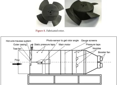
The designed and calculated half-ducted rotor with four NACA65 blades was fabricated by a three-dimensional printer shown in Figure 8 and tested in the wind tunnel in order to validate the half-ducted design method. The rotor has been tested in experiment equipment system in Figure 9 with an 880 mm × 880 mm square cross section and a length of 3 m. The rotor speed can arbitrarily set on the range of 0 to 3100 min−1 driven by the direct-current electric motor. In
[image:8.595.136.539.421.713.2]order to get smaller static pressure rise, the centrifugal fans were set in the outlet of the system. The flow rate of the system can be well controlled by altering the
Figure 8. Fabricated rotor.
rotating speed of the booster fan. Axial torque coefficient and efficiency are de-fined as:
(
2 2)
38
t h t
T
D D U
ω τ
π ρ
=
− (8)
s
p Q T
η
ω
∆ ⋅ =
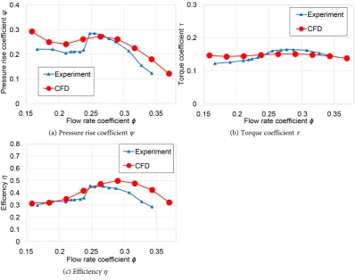
⋅ (9) The static pressure of the propeller fan is obtained by averaging the data from 16 static pressure taps setting at downstream of rotor as show in Figure 10. The flow rate is calculated by the differential pressure between the upstream and downstream of the nozzle where eight pressure taps are set respectively. The higher flow rate, corresponding to larger differential pressure, can be obtained by elevating the rotating speed of two centrifugal booster fans, and the rotor speed is set by 3000 min−1 in this paper. Calculated and measured pressure rise,
torque and efficiency is shown in Figure 10. For the comparison between the design values and the experimental values at the design flow rate coefficient of φ= 0.264, the experimental values of the pressure rise coefficient ψ and the efficiency
η are rather small than the design values, while the experimental value of the torque coefficient is almost the same as the design value. However, the experi-mental value of approximately 0.45 of the maximum efficiency is comparably large value considering for the limitation of the situation of half-ducted. For the comparison between the experimental values and the CFD values at the design
(a) Pressure rise coefficient ψ (b) Torque coefficient τ
[image:9.595.138.538.406.720.2](c) Efficiency η
flow rate coefficient of φ= 0.264, the CFD values are almost the same values as the experimental values for all the values of ψ, τ and η. In addition, the tenden-cies of the CFD values when the flow rate coefficient changes are almost similar as the experimental tendencies, though the flow rate coefficient for the CFD val-ues when ψ or η takes the peak value shifts toward larger flow rate.
6. Conclusions
The half-ducted axial flow fan was designed by a diagonal flow fan design me-thod.
Half-ducted fans have been designed, numerically analyzed, manufactured and tested to confirm the effect of this design method for improving design me-thod on the overall performance and the three-dimensional flow field in design. The conclusions are summarized as follows.
1) For the comparison between the design values and the experimental values at the design flow rate coefficient of φ= 0.264, the experimental values of the pressure rise coefficient ψ and the efficiency η are rather small than the design values, while the experimental value of the torque coefficient τ is almost the same as the design value. However, the experimental value of approximately 0.45 of the maximum efficiency is comparably large value considering for the limita-tion of the situalimita-tion of half-ducted.
2) For the case at rotor outlet, at the flow rate coefficient of φ = 0.264, two values of the meridional velocity and the tangential velocity are larger than the design values at the tip side of the radial distribution. On the other hand, the values of Cm and Cθ at rotor outlet are smaller than the design values at the hub side of the radial distribution. The improvement of the design is prospected for this point, that is, the approach between the design value and the actual flow is prospected if the tangential velocity is assigned small at the hub and is as-signed large at the tip so as to accord the actual flow in the vortex design of the rotor blade.
3) For the comparison between the experimental values and the CFD values at the design flow rate coefficient of φ= 0.264, the CFD values are almost the same values as the experimental values for all the values of ψ, τ and η. In addition, the tendencies of the CFD values when the flow rate coefficient changes are almost similar as the experimental tendencies, though the flow rate coefficient for the CFD values when ψ or η takes the peak value shifts toward larger flow rate.
Acknowledgements
The authors would like to acknowledge the financial support of Saga University for this research project.
References
[2] Zangeneh, M., Goto, A. and Harada, H. (1998) On the Design Criteria for Suppres-sion of Secondary Flows in Centrifugal and Mixed Flow Impellers. ASME Transac-tions on Journal of Turbomachinery, 120, 723-735.
https://doi.org/10.1115/1.2841783
[3] Goto, A. (2016) Historical Perspective on Fluid Machinery Flow Optimization in an Industry. International Journal of Fluid Machinery and Systems, 9, 75-84.
https://doi.org/10.5293/IJFMS.2016.9.1.075
[4] Shiomi, N., Kinoue, Y. and Setoguchi, T. (2012) Three Dimensional Velocity Fields at Rotor Outlet of a Semi-Opened Propeller Fan. Turbomachinery, 40, 218-225. (In Japanese)
[5] Shiomi, N., Kinoue, Y. and Setoguchi, T. (2012) Experimental Study on Flow Fields with Vortex in a Semi-Opened Propeller Fan. Turbomachinery, 40, 688-696. (In Japanese)
[6] Liu, P., Oka, Y., Kinoue, Y., Shiomi, N., Setoguchi, T. and Jin, Y. (2013) Design of Half-Ducted Axial Flow Fan Considering Radial Inflow and Outflow. Open Journal Fluid Dynamics, 3, 1-8. https://doi.org/10.4236/ojfd.2013.32A001
[7] Novak, R.A. (1967) Streamline Curvature Computing Procedures for Fluid-Flow Problems. ASME Transactions on Journal of Engineering for Power, 89, 478-490. https://doi.org/10.1115/1.3616716
[8] Inoue, M., Ikui, T., Kamada, Y. and Tashiro, M. (1980) A Quasi Three-Dimensional Design of Diagonal Flow Impellers by Use of Cascade Data. Proceeding of 10th Symposium of IAHR, Tokyo, 403-414.
Submit or recommend next manuscript to SCIRP and we will provide best service for you:
Accepting pre-submission inquiries through Email, Facebook, LinkedIn, Twitter, etc. A wide selection of journals (inclusive of 9 subjects, more than 200 journals)
Providing 24-hour high-quality service User-friendly online submission system Fair and swift peer-review system
Efficient typesetting and proofreading procedure
Display of the result of downloads and visits, as well as the number of cited articles Maximum dissemination of your research work
Submit your manuscript at: http://papersubmission.scirp.org/