International Journal of Emerging Technology and Advanced Engineering
Website: www.ijetae.com (ISSN 2250-2459,ISO 9001:2008 Certified Journal, Volume 4, Issue 10, October 2014)
224
VLSI Architecture for Efficient Lifting-Based Forward and
Inverse DWT
A. Kishore kumar1, Dr. M. Satyanarayana2
Electronics and Communication Engineering Dept., M.V.G.R College of Engineering, Vizianagaram, India
Abstract— The wavelet transform is denoted by ‘WT’ gained wide-ranging approval in processing signal and in compressing image. A 2D analysis must be implemented to use WT for processing the image. Such powerful signal analysis technique can be implemented for non-stationary data using Lifting architecture for the Discrete Wavelet Transform (DWT). Since high speed implementation with low latency is a demanding task, so in this work, separable pipelining architecture is proposed for rapid computation for two-dimensional one, discrete wavelet transform in lifting-based and by appropriate designing and also well transfer of the information among the two 1-D ‘DWT filters’, the small latency is achieved. In this article, separable pipelining architecture is also proposed for Inverse discrete wavelet transform (IDWT) which is based on inverse lifting scheme. Verilog HDL is used as a programming language to implement the above architectures and their simulation results are also presented.
Index Terms—Discrete wavelet transform (DWT), VLSI architecture, lifting schemes, pipeline.
I. INTRODUCTION
Discrete wavelet transform (DWT) be known as a analysis tool which gives multi-resolution with tremendous characteristics in time domain and frequency domains. Signals using DWT is decomposed into diverse sub - bands having time information as well as frequency content. When Compared, the coding efficiency and the quality of image restoration with the DWT are higher than the traditional discrete cosine transform. Also, higher in compression ratio be easily obtained. Consequently, DWT is extensively used in processing of signal and compression of image, for instance JPEG2000, MPEG-4 and in many more [3], [4]. Traditional DWT architectures [6], [7] are convolution-based and the second-generation DWTs are lifting algorithms based, those are proposed [8], [9]. Lifting-based architectures have lesser computation complexity and also need less hardware resource compared with convolution-based DWTs.
The later part of the paper is structured as follows. Section II review about what Discrete Wavelet Transform (DWT) is. Section III and IV reveals the projected architecture for the 2-D DWT and also for Inverse DWT which is used for reconstruction.
Section V provides results after implementing for both forward and inverse DWT. Performance comparison within various VLSI architectures is also presented in this section. At last, Concluded in Section VI.
II. DISCRETE WAVELET TRANSFORM
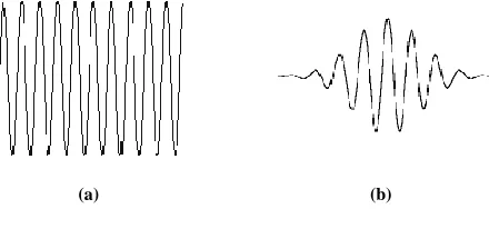
In general form „wavelet‟ is defined as a small wave which concentrates all its energy in terms of time. Though it is an oscillating wave like feature, can capable in allowing instantaneous time analysis and frequency analysis and this is considered as a prominent means for transient and non transient( non-stationary) phenomena.
(a) (b)
Figure 1. (a) A Wave (b) A Wavelet
[image:1.612.331.551.385.488.2]International Journal of Emerging Technology and Advanced Engineering
Website: www.ijetae.com (ISSN 2250-2459,ISO 9001:2008 Certified Journal, Volume 4, Issue 10, October 2014)
225 This wavelet analysis adopts a wavelet model function, known as „mother wavelet‟ or „analyzing wavelet‟. Frequency analysis perform with a dilate, low frequency description of the model wavelet, where as temporal analysis is formed with a constricted, high frequency description of same wavelet. Arithmetical form for signal expansion by means of the wavelets outputs pair of wavelet transform (WT), that is equivalent to the pair of Fourier Transform (FT). Discrete-parameter and discrete in time of WT is coined as Discrete wavelet transform.
A.Characteristics of DWT
a. Because of its multi-resolution nature they are suitable for applications which require scalability and tolerable degradation. So it allows progressive transmission of images.
b.The larger the magnitude of the wavelet coefficient the more significant it is.
c. Magnitude of DWT coefficients is larger in the lowest bands (LL) at each level of decomposition because they consists pixels of approximate image.
d.Magnitude of DWT coefficients is smaller for other bands (HH, LH, and HL).
e. With DWT the edges and texture can be easily identified in the high frequency bands like HH, LH, and HL. The large coefficients in these bands normally indicate edges in the image.
f. Low frequency components have larger perceptual capacity compared to high frequency components because they have large magnitudes.
III. PROPOSED ARCHITECTURE FOR THE 2D DWT
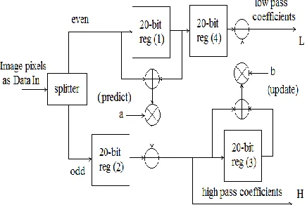
Proposed a pipeline architecture for 2-D Discrete wavelet Transform (DWT) having low latency which is shown in figure 2.
Figure 2. Proposed Architecture for 1D-DWT
In the primary stage of the architecture, given input data is divided as odd and even positions respectively. Even positioned pixels are then fed through 20-bit register (1) where the summation is performed for the data predicted on the further side of data analysis where the odd positioned pixels are added in 20-bit register (2). The obtained data is then summed with data of output gained from register of 20-bit (3). All at once, parallel data is received in the form of Low-pass plus High-pass coefficients on both sides.
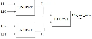
[image:2.612.336.551.292.392.2]Now the same 1D-DWT design is used to implement a complete one level 2D-DWT by separable pipeline architecture as shown in the below figure 3.
Figure 3. separable pipeline Architecture for one level 2D-DWT
This separable pipeline architecture explains about the transmission of data efficiently in both 1-D DWT and 2D-a DWT simultaneously. The transmission of data is observed in XILINX tool.
IV. PROPOSED ARCHITECTURE FOR THE IDWT In the inverse case predicted step is compared with updated step and their polarities are interchanged. This is done by reversing the order of operations. So to define for forward and its inverse can use same resources.
[image:2.612.52.270.553.699.2]International Journal of Emerging Technology and Advanced Engineering
Website: www.ijetae.com (ISSN 2250-2459,ISO 9001:2008 Certified Journal, Volume 4, Issue 10, October 2014)
[image:3.612.330.554.131.298.2]226
Figure 4. Proposed Architecture for 1D-IDWT
[image:3.612.74.264.145.265.2]In this the values b and a is taken as 1 for digital design purpose. If we take those values as 0 then it became Zero response. Merge is used to join the values and the 20 bit registers are used to store the values and transfer the values. The adders are used to add the original and delay values of the register. By separable pipeline architecture we can reconstruct Original data as shown in Figure 5.
Figure 5. separable pipeline Architecture for IDWT
V. IMPLEMENATATION RESULTS
The architectures proposed for forward DWT and inverse DWT are synthesized and simulated using Xilinx tool.
A.Forward DWT
[image:3.612.325.567.339.538.2]Forward 2D-DWT using separable pipeline architecture is synthesized and its obtained schematic architecture is shown in figure 6.
Figure 6. Schematic of separable pipeline architecture
Simulation results obtained forForward 1D-DWT using separable pipeline architecture is shown in figure 7
Figure 7. Simulation result of 1D-DWT
[image:3.612.93.251.379.447.2]International Journal of Emerging Technology and Advanced Engineering
Website: www.ijetae.com (ISSN 2250-2459,ISO 9001:2008 Certified Journal, Volume 4, Issue 10, October 2014)
[image:4.612.52.288.132.275.2]227
Figure 8. Simulation result of 2D-DWT
B.Inverse DWT:
[image:4.612.332.554.146.368.2]Inverse DWT is synthesized and its obtained schematic architecture is shown in figure 9
Figure 9. Schematic of pipeline Architecture for IDWT
[image:4.612.58.279.333.491.2]Simulation results obtained for reconstruction of Original image pixels by proposed architecture is shown in figure 10.
Figure 10. IDWT simulation results
C.Synthesis Report
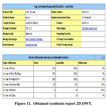
Figure 11. Obtained synthesis report 2D DWT.
Figure 11 gives details about Total Time Delay which is 14.421ns (11.427ns logic, 2.994ns route) and Total memory usage as 140532 kilobytes and Number of errors is 0 (0 filtered).
Table I, describes about architectural internal design considering RAMs, comparators, flips flops, adders and counters as blocks used.
TABLE I. Advanced HDL design report
Logic Utilization Used
RAMs utilized in number
13x20-bit dual-port block RAM 9x20-bit dual-port block RAM
6 2 4
ROMs (32x20-bit) utilized in number 1
20-bit adders utilized 15
Counters used in number
32- bit up counter
4- bit up counter
7 1 6
Registers (Flip-Flops) 328
Comparators
4- bit comparator greater 4- bit comparator less than equal
[image:4.612.326.556.477.722.2] [image:4.612.60.278.540.703.2]International Journal of Emerging Technology and Advanced Engineering
Website: www.ijetae.com (ISSN 2250-2459,ISO 9001:2008 Certified Journal, Volume 4, Issue 10, October 2014)
228
D.Comparison Results
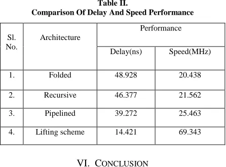
[image:5.612.57.280.192.357.2]Various existing architectureS and proposed architectures are compared in terms of delay and speed performance. This comparison is briefed in Table II.
Table II.
Comparison Of Delay And Speed Performance
Sl. No.
Architecture
Performance Delay(ns) Speed(MHz) 1. Folded 48.928 20.438 2. Recursive 46.377 21.562 3. Pipelined 39.272 25.463 4. Lifting scheme 14.421 69.343
VI. CONCLUSION
Data compression can be achieved by discarding these low amplitudes. In order to achieve better compression first identification of decomposed signals is required which is done according to present thesis. This work presents how signal decomposition occurs through separable DWT architecture. Separable pipelining architecture for rapid computation of the two dimensional DWT with less memory and lesser latency is presented in this paper by appropriate designing and also well transfer of data within two one dimensional DWT filter. separable pipeline architecture for Inverse Discrete wavelet transform (IDWT) is also proposed. The proposed architectures are implemented in verilog language and simulated, synthesized using Xilinx ise 12.3 version tool. The customized lifting scheme circuit uses pipelining of three stages with less registers and low in critical path delaying.
Comparison of proposed architecture with existed one is done and then revealed that the architecture proposed achieves higher speed, lower hardware complexity and storage size is less. In future this work can be applied to frames also.
Acknowledgment
Our sincere thanks to all the staff of the M.V.G.R College for their support in bringing this paper.
REFERENCES
[1] Wei zhang, Zhe jiang, Zhiyu gao, and Yanyan liu, “An Efficient VLSI Architecture for Lifting-Based Discrete Wavelet Transform,”
IEEE Trans. Circuits Syst. II, Exp.Briefs, vol. 59, no. 3, Mar 2012. [2] J. Ravi babu, R. ravali, “A High Speed Optimization for Fast
Computation of 2-D DWT”, International Journal for Advanced Research in Computer Science and Software Engineering (IJARCSSE), vol. 3, May 2013.
[3] G. Xing, J. Li, and Y. Q. Zhang, “Arbitrarily shaped video-object coding by wavelet,” IEEE Trans. Circuits Syst. Video Technol., vol. 11, no. 10, pp. 1135–1139, Oct. 2001.
[4] S. C. B. Lo, H. Li, and M. T. Freedman, “Optimization of wavelet decomposition for image compression and feature preservation,”
IEEE Trans.Med. Imag., vol. 22, no. 9, pp. 1141–1151, Sep. 2003. [5] K. K. Parhi and T. Nishitani, “VLSI architecture for discrete
wavelet transforms”, IEEE Trans., Very Large Scale Int., (VLSI) Syst., vol. 1, no. 2, pp. 191–202, Jun. 1993.
[6] Andra, K. Chakrabarti, C. and Acharya, T. “A VLSI Architecture for Lifting-based Forward and Inverse Wavelet Transform,” IEEE Trans.Signal Process., Vol. 50, No. 4, pp. 966–977, 2001.
[7] Wu, P.C. and Chen, L.G. “An Efficient Architecture for Two-Dimensional Discrete Wavelet transform,” IEEE Trans. Circuits Syst. Video Technol., Vol. 11, No. 4, pp. 536–545.
[8] Dillen G. et al., “Combined Line-Based Architecture for the 5-3 and 9-7 Wavelet Transform of JPEG2000,” IEEE Trans. Circuits & Systems for Video Tech., vol. 13, no. 9, pp. 944-950, Sept. 2003. [9] Barua, S. Carletta J.E., Kotteri K.A., and Bell A.E., “Efficient
architecture for Lifting-Based 2-D discrete wavelet transform, “Integration, the VLSI, vol. 38, no. 3, pp. 341-352, 2005.