Use of finite element analysis to
investigate the structural behaviour of
masonry arch bridges subject to
foundation settlement
Naggasa, AM, Augusthus Nelson, L and Haynes, BJ
Title Use of finite element analysis to investigate the structural behaviour of masonry arch bridges subject to foundation settlement
Authors Naggasa, AM, Augusthus Nelson, L and Haynes, BJ
Type Conference or Workshop Item
URL This version is available at: http://usir.salford.ac.uk/46832/
Published Date 2018
USIR is a digital collection of the research output of the University of Salford. Where copyright permits, full text material held in the repository is made freely available online and can be read, downloaded and copied for noncommercial private study or research purposes. Please check the manuscript for any further copyright restrictions.
10th IMC
10th International Masonry Conference
G. Milani, A. Taliercio and S. Garrity (eds.) Milan, Italy, July 9-11, 2018
USE OF FINITE ELEMENT ANALYSIS TO INVESTIGATE THE
STRUCTURAL BEHAVIOUR OF MASONRY ARCH BRIDGES
SUBJECT TO FOUNDATION SETTLEMENT
A.Naggasa1, L. Augusthus-Nelson2, J. Haynes3
1 Directorate of Civil Engineering, University of Salford
Newton Building, Salford, Greater Manchester, M5 4WT e-mail: [email protected]
2 Directorate of Civil Engineering, University of Salford
Newton Building, Salford, Greater Manchester, M5 4WT e-mail: [email protected]
3 Directorate of Civil Engineering, University of Salford
Newton Building, Salford, Greater Manchester, M5 4WT e-mail: [email protected]
Keywords:Masonry arch bridges, FEM, settlement, ABAQUS, soil-structure interaction.
1 INTRODUCTION
1.1 History and Background
Masonry arches are some of the oldest structures in the world [1]. These structures were built by the Romans more than two thousand years ago and by several civilisations before them [2]. Furthermore, the first examples of masonry arch bridges were built in the Middle East, Mesopotamia and China around 5000 years ago [3 & 4]. The Chinese employed the method of corbelled horizontal courses 4,900 years ago. However, it became apparent that it was not efficient or practical for long spans [5]. The Egyptian elliptical brick arch may be considered the first voussoir arch, where it was used in Amenophis I tomb around 1800BC [6].
Masonry arches were used extensively for the construction of mediaeval cathedrals, rail and road bridges throughout the industrial revolution [7]. The masonry arch bridge structure is still considered an elegant and structurally efficient form. The reason for their extensive use is due to their ability to provide large open spans without requiring materials with high tensile strength. However, for many centuries, these structures were constructed through trial and er-ror, as their complex behaviour made them difficult to understand [8]. In fact, the study of their structural performance has only been documented since the 17th century. Masonry arch bridges are constructed from various materials such as stone, clay brick, mortar and backfill (often soil).
There are approximately 40,000 masonry arch bridges in the UK that are still in service at the current time. Around 60% of these bridges are over 100 years old, being constructed be-tween the 17th and 19th centuries [9], this shows masonry is a durable material. The majority of UK masonry arch bridges are owned by navigable waterway, highway and railway authori-ties [10]. However, because of loading increases and inevitable material degradation, these bridges require assessment and possibly repair.
1.2 Analysis Process
Four levels of investigation have been suggested for arch bridge capacity assessment, only if a bridge fails an assessment is a more complex assessment level investigated. An approxi-mate calculation such as the MEXE method is the first level; simple 2D modelling such as thrust line analysis and rigid block methods are the second level; more advanced 2D and 3D modelling, such as the mechanism analysis method or the Discrete Element Method (DEM) are the third level; and modelling using the Finite Element Method (FEM) is the fourth level.
MEXE is based on the elastic method created by Pippard, and is used to initially assess load carrying capacity accounting for the condition of the arch using a series of imprecise modification factors [11]. There are known to be criticisms of this system when assessing short or long span bridges [10, 12, 13 & 14].
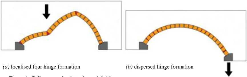
Figure 1: Collapse mechanisms for arch bridges on (a) rigid and (b) moving foundations.
The recent proliferation of cheap and powerful computing has led to greater use of both FEM and DEM methods, which permit simulations of structural models that can address the nonlinear material and geometry behaviour of the masonry arch. The ability to also model damage and degradation can lead to potentially useful evaluation of the load capacity of exist-ing bridges.
Modelling of an arch as it approaches collapse, requires numerical methods to adopt a means of representing cracks between brick and mortar. DEM does this by changing node connectivity and creating separations between element edges, however continuous change in node connectivity does not fit the finite element displacement method formulation [16].
This research uses FEA non-linear material and geometry analysis to simulate the behav-iour of a single span masonry arch bridge, subject to foundation movement. FEA is an ap-proximate means of describing a problem with near infinite degrees of freedom in such a way that understandable output can be used for design purposes.
2 PHYSICAL TESTING
Full-scale plain-strain testing of masonry arch bridges has been undertaken at the Universi-ty of Salford Heavy Structures Laboratory for many years [17,18]. To extend these tests, a small scale test apparatus was developed. The arch barrel voussoirs were manufactured from Hermiculite plaster and the mortar was replaced by rubber sheet. A movable joint was located at the right hand abutment in order to model foundation settlement, sliding and rotation. This paper will address foundation settlement characteristics.
3 NUMERICAL MODELLING
The ABAQUS program was selected to create FEA models, in which masonry may be modelled as either homogeneous or heterogeneous. To create a model as representative as possible heterogeneous material modelling was chosen, combined with an interface model for the joint between the mortar and bricks.
3.1 Introduction
3D models of the small tank masonry arch bridge test were created. The bridge was mod-elled as backfill (sand); an arch barrel, composed of bricks and mortar; and two abutments, where the right abutment was forced to settle. Full representation of the arch components was achieved including the individual mortar joints.
3.2 Geometry
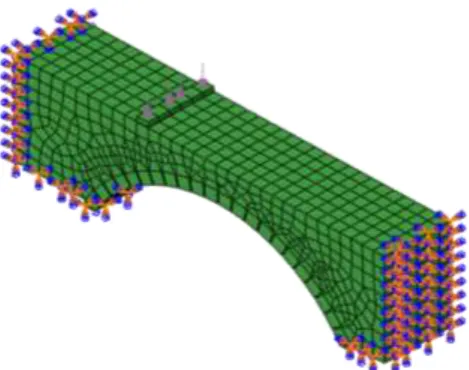
[image:5.595.174.537.160.354.2]The bridge geometry was modelled using AutoCAD and imported into ABAQUS, where restraints were applied at the arch barrel abutments and the vertical ends of the backfill. In order to model the restraint of the small tank walls, out-of-plane restraints were also applied to the faces of the backfill.
Figure 2: Geometry of the small scale model (mm).
Figure 3: ABAQUS model (backfill out-of-plane restraints not shown for clarity).
3.3 Material Properties
The bricks were defined as a purely elastic linear material, of infinite strength. The section and material properties were assumed to be isotropic.
The mortar was defined as a concrete-like plastic material, offering a strain in compression and tension with damage concrete plasticity. The mortar joints were placed between the bricks, where the damage (cracking) of the bridge occurs. The mortar joint compressive strength and tensile strength were 1.3 MPa and 0.36 MPa respectively.
The backfill material was modelled as a non-linear Mohr-Coulomb material, using a dila-tion angle of 15o, an internal friction angle of 38o and cohesion of 7 kPa. The model assumes non-associated plastic flow.
533 150
2
5
5
0
174
[image:5.595.186.421.373.558.2]The abutments and loading plate were modelled using the properties of mild steel. The values for the four constituent materials are shown in Table 1 [19 & 20].
Brick Mortar Backfill Abutment
Density (kg/m3) 2226 1400 1800 7850
Modulus of elasticity, E (MPa) 16000 16000 40 210000
Poisson’s ratio, 0.20 0.19 0.30 0.30
[image:6.595.97.499.121.254.2]Compressive strength, fc (N/mm2) 1.3 Tensile strength, ft (N/mm2) 0.36
Table 1: Material properties for the bridge constituent parts.
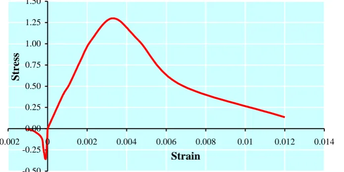
ABAQUS provides the ability to model concrete in three different ways, the concrete dam-age plasticity model was chosen for this project as it represents non-linear behaviour in both compression and tension. This is depicted in Figure 4.
-0.50 -0.25 0.00 0.25 0.50 0.75 1.00 1.25 1.50
-0.002 0 0.002 0.004 0.006 0.008 0.01 0.012 0.014
Strain
Str
es
s
Figure 4: The stress-strain relationship for mortar.
3.4 Connectivity
Computational efficiency in the analysis of complex finite element models is often achieved by the use of macro modelling (where many materials may be represented by homo-geneous elements with smeared material properties). When highly detailed results are re-quired, micro modelling may be used (where masonry units are subdivided) but at the detriment of computational efficiency. For this project meso-scale modelling was adopted as it is known to be efficient in the solution of composite problems [21], it allows the cracking of mortar to be developed effectively, and this stage of the project is to be validated by global structural behaviour rather than detailed stress values.
The model is constituted by eight nodded, 3D quadrilateral finite elements of varying shape.
[image:6.595.139.487.338.512.2]Interaction between the bricks and backfill was modelled by merging the element surfaces of each individual brick unit to its adjacent backfill element. This ensures that backfill is dis-placed when the arch barrel moves.
3.5 Restraints
With the exception of the upper surface of the backfill, the outer surfaces were restrained. Supports at the abutment ends of the backfill were restrained in all directions but without rota-tional restraint. The supports on the front and rear surfaces were only restrained against out-of-plane displacement, this ensured the plain-strain movement observed in physical testing.
Loading was applied in the form of a forced displacement at the underside of the load plate. This models displacement control and allows post-buckling behaviour to be observed.
3.6 Test Methodology
The aim of the study was to determine whether abutment settlement changes the structural behaviour of the arch barrel at collapse. Therefore, models were analysed using two fixed abutments; and with one settling right abutment.
For the fixed abutment models, vertical displacements of 1.0, 2.0, 6.0 and 20.0mm were applied at the load plate.
For the settling abutment models, a vertical displacement of 9.0mm was applied at the load plate. In addition the settling abutment was forced to displace vertically downwards by 3.0, 4.5 and 6.0mm.
4 RESULTS AND DISCUSSION
Figures 5 and 6 present force-displacement curves for fixed and settling abutment models, respectively. Values for the force axis were obtained from the ABAQUS model by averaging the axial stress at the fourteen nodes which form the loading plate. Values for the displace-ment axis were obtained for a single central node at the arch barrel crown intrados.
4.1 Arch on Fixed Abutments
The force-displacement curve for an arch on fixed abutments shows a high initial stiffness with a pronounced peak elastic value, where after plastic displacements ensue. Elastic placement peaks at about 0.5mm and for maximum load displacement the arch barrel dis-placement was 14mm. There is a very small post-yield stiffness.
Figure 5: Load – displacement of arch on fixed abutments.
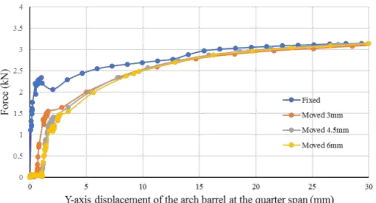
4.2 Arch on Settling Abutment
The force-displacement curve for an arch on settling abutments shows a high initial stiff-ness but without a pronounced change from elastic to plastic behaviour. This is believed to be because the settling model shows a more dispersed development of hinges in the barrel (many smaller rotation hinges are forming).
In comparison to the fixed abutment model, the settling model begins to suffer stiffness softening at approximately half the peak force. At this point the vertical displacement of the settling model is approximately ten times that of the fixed model.
When the vertical displacement reaches 15mm, the capacity of the fixed and settling mod-els is essentially the same.
There is very little difference between the initial stiffness of the three settling models.
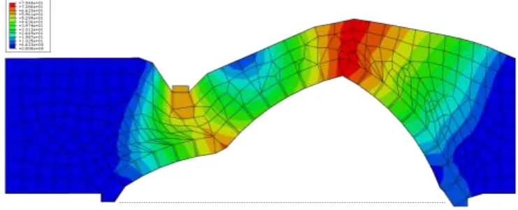
[image:8.595.118.503.493.701.2]Figure 7 shows the arch model which was subject to 9mm of vertical displacement at the load plate and 3mm vertical settlement at the right abutment. Four hinges have formed; adja-cent to each abutment and at approximately quarter and three-quarter spans. The majority of backfill movement is located close to the arch barrel, in the first and last quarter spans.
Figure 7: Deformed shape of arch with settlement.
4.3 Discussion
Previous work on finite element analysis of masonry arch bridges has either modelled mor-tar joints of zero thickness, or has not considered backfill restraint. This project has used me-so-modelling to address both of these shortcomings.
Analysis of the model with vertical foundation settlement produced behaviour which was validated by observation of the small scale tests. However, for settlements which approached span/100, the solution of the numerical model produced results which suggested there was difficulty in reflecting a realistic deformed shape for the zone adjacent to the settling abut-ment. The shape of some deformed mortar joints indicates developing local instability of the structure.
Analysis run time is significantly extended when large settlements are forced on the model, this is probably linked to the unrealistic distortion of mortar joints in the settling abutment ar-ea.
The finite element method adopted here cannot accurately reflect brittle hinges formed in or between the mortar and brick, as observed in reality. This is a shortcoming which is be-lieved to exacerbate solution problems for model subject to large foundation settlements.
5 CONCLUSION
Figures 5 and 6 suggest that foundation settlement detrimentally affects the initial stiffness of a masonry arch bridges but as displacement of the barrel advances the stiffness of fixed and settling arches converges at a very similar ultimate load capacity.
Since most masonry arch bridges operate at relatively low levels of vertical displacement, this study suggests that masonry arch bridges subject to settlement will deform significantly more at working loads, which will generate ongoing durability issues.
6 REFERENCES
[2] F. Catbas, S. Pakzad, V. Racic, A. Pavic, & P. Reynolds, Topics in Dynamics of Civil Structures, Volume 4: Proceedings of the 31st IMAC, A Conference on Structural Dy-namics, Springer Science & Business Media, 2013, v39.
[3] S. Chatterjee, Assessment of Old Bridges. Highways & Transportation, 33(2), 18-22, 1985.
[4] J. Page, Masonry Arch Bridges, TRL-State of the art review, Department of Transport: HMSO, London, 1993.
[5] V. Apreutesei & D.V. Oliveira, Strengthening of Stone Masonry Arch Bridges− Three Leaf Masonry Walls – State of the Art. Oliveira, D.V. (ed): Guimaraes, 2005.
[6] H.S. Smith, The world's great bridges. Harper & Row: American Geographical Society, 1965.
[7] D. Seward, Understanding structures: analysis, materials, design, 5th edition. Palgrave Macmillan: Basingstoke, 2014.
[8] S. Ponnuswamy, Bridge Engineering, 2nd edition, McGraw-Hill Education: India, 2008.
[9] C. Melbourne, L.D. McKibbins, N. Sawar & C. Sicilia Gaillard, Masonry arch bridges: condition appraisal and remedial treatment C656, CIRIA: London, 2006.
[10] C. Melbourne, J. Wang, & A.K. Tomor, A new masonry arch bridge assessment strate-gy (SMART), Proceedings of the ICE - Bridge Engineering,160(2), 81-87, 2007. [11] N. Gibbons & P.J. Fanning, Rationalising assessment approaches for masonry arch
bridges. Proceedings of the Institution of Civil Engineers: Bridge Engineering, 165(3),
169-184, 2012.
[12] J. Wang, J. Haynes & C. Melbourne, A comparison between the MEXE and Pippard's methods of assessing the load carrying capacity of masonry arch bridges, ARCH’13 – 7th International Conference on Arch Bridges, Trogir-Split, Croatia, 2013, 589–596.
[13] J. Wang, J. Haynes & C. Melbourne, Investigation of assessment methods for railway masonry arch bridges, ARCH ’16 - 8th International Conference on Arch Bridges, Wroclaw, Poland, 2016, 434–439.
[14] W.J. Harvey, E.A.W. Maunder & A.C.A. Ramsay, The influence of spandrel wall con-struction on arch bridge behaviour. In Proceedings of the 5th international conference on arch bridges ARCH, 2007, vol. 7, p. 601-608.
[15] J. Heyman, The masonry arch, Ellis Horwood: Chichester, 1982.
[16] J.G. Rots, Computational modelling of concrete fracture, 1988. Technische Hogeschool Delft.
[17] G.M. Swift, L. Augusthus-Nelson, C. Melbourne & M. Gilbert, Physical modelling of cyclically loaded masonry arch bridges, ARCH’13 – 7th International Conference on Arch Bridges, Trogir-Split, Croatia, 2013, 621-628.
[18] L. Augusthus-Nelson, G. Swift, C. Melbourne, C. Smith, M. Gilbert, Large-scale physi-cal modelling of soil-filled masonry arch bridges. International Journal of Physical Modelling in Geotechnics, 2018, currently in print.
[20] Ł. Hojdys, T. Kaminski & P. Krajewski, Experimental and numerical simulations of collapse of masonry arches, ARCH’13 – 7th International Conference on Arch Bridges, Trogir-Split, Croatia, 2013, 715-722.